pj_mcgarvey's - LS1/T56 NB build thread

 03-06-2017, 06:52 AM
#126
V8 Miata Enthusiast
Thread Starter

I was able to upload some video finally. Here is the startup video. Not the very first startup but we'll call it that since everything on the car was mostly functioning by this time.
Next was after the car had warmed up a bit there was a bit smoother idle and throttle blips. You can see I had the fan going on the trunk b/c of all the stuff burning off the engine and exhaust smoke.
One thing I wanted to share was the belt tensioner seemed busy. This is a new tensioner, does this look normal to anyone? Seems to be moving around alot but appears to stay near the two marks that I assume are to check it's in the proper adjustment range?
As mentioned before need to figure out the check engine light I'm getting, and the coolant overflow issue before I do any more testing.
I have much of the interior back together too but leaving alot of it loose in case I need to get back into the top of the fuel tank area. See my earlier post on the emissions/tank venting if you have any input on how to do that. I'll be doing some research to see what hot rodders do that don't need to pass emissions 100%.

 03-06-2017, 08:11 PM
#129
V8 Miata Enthusiast
Thread Starter
Figured out my OBD port issue pretty quickly, turns out I needed to repin the OBD port as the data connection wasn't in the right place on the connector.
This post DIY: LS1 OBD2 Port Install - ClubRoadster.net was helpful in figuring this out. Basically you need to move the wire that carries the data connection to the PCM to pin 2.
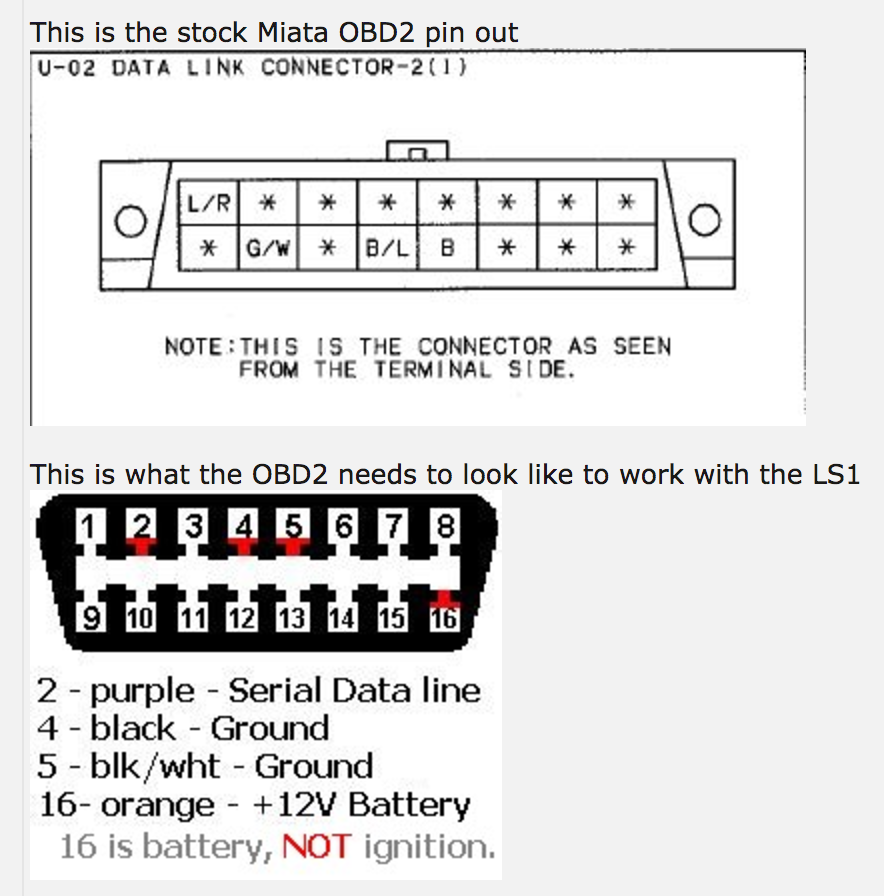
You'll need to remove this white plastic piece from the back by just undoing a clip on one side and lifting it up
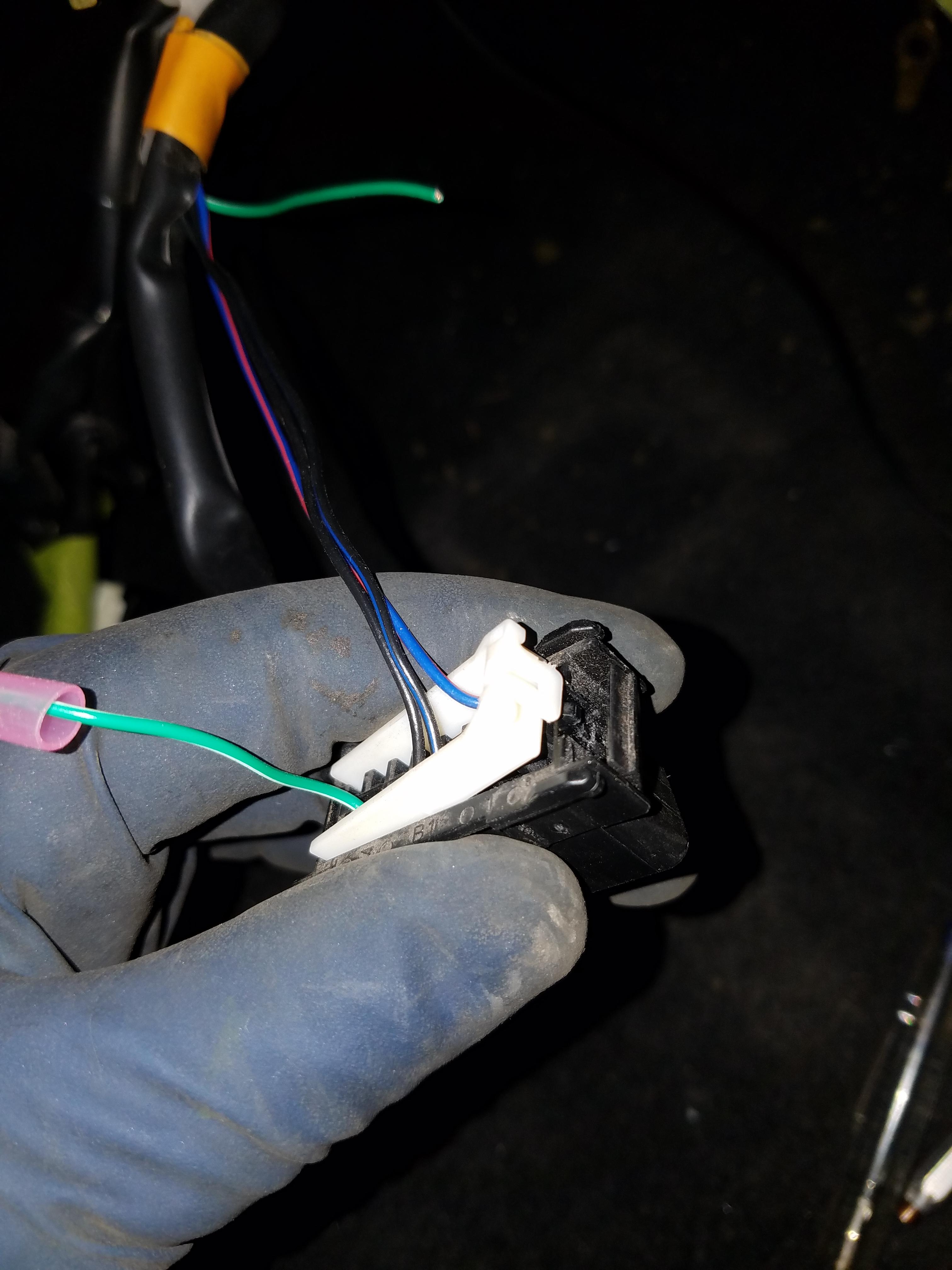
On my 99 Miata, the green/yellow wire was the data line which was located over on pin 7. In order to depin it just look at the pin from the front side of the connector and use a small pick to lift up the plastic tab I pointed to with the arrow.
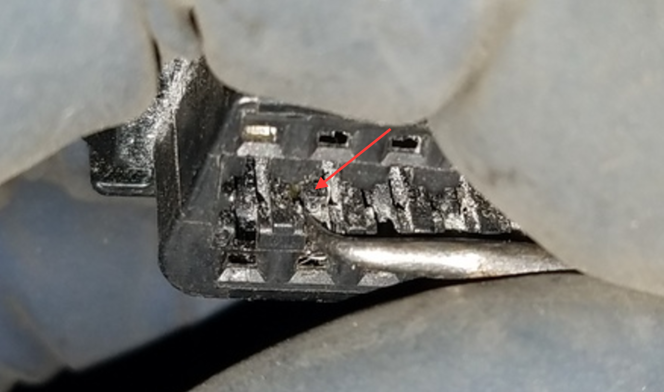
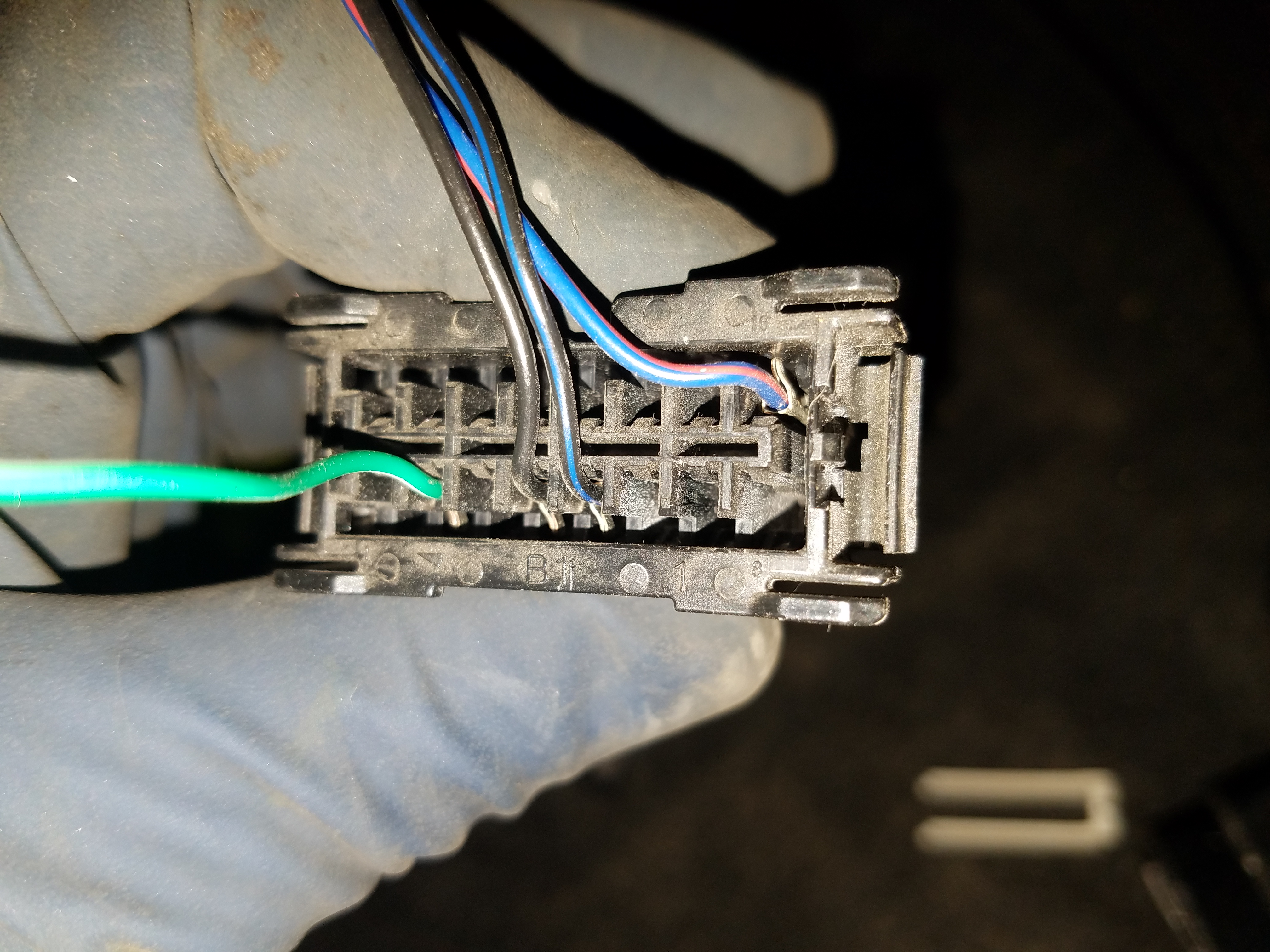
Pull the wire from the back as you lift the tab and it should come out. Put it back on the pin 2 location so it should look like this from the back.
My CEL was related to both oxygen sensors having "no activity". It threw the code a few minutes after the engine was started, and I did verify the O2 sensors were both working fine when I started the car. I'll need to look into this a bit more and see if I have a bad connection. One of my sensors is new, the other is original to the engine.
I'm still having a cooling issue where the overflow tank goes from empty at startup to almost overflowing at full warm, the rad cap starts to emit steam. All the hoses are getting warm so I'm thinking the thermostat is opening. But I wasn't getting any heat from the hvac system. My fans were also not kicking on at any point.
My tach is reading about double the RPM of the engine speed. I'm not using a resistor as Flyin Miata describes, but I have one so I think I'll need to install it.
Did a couple small jobs like make a plug for the firewall hole previously was used for the engine harness. Just found a rubber plug and coated in some RTV and let it set.
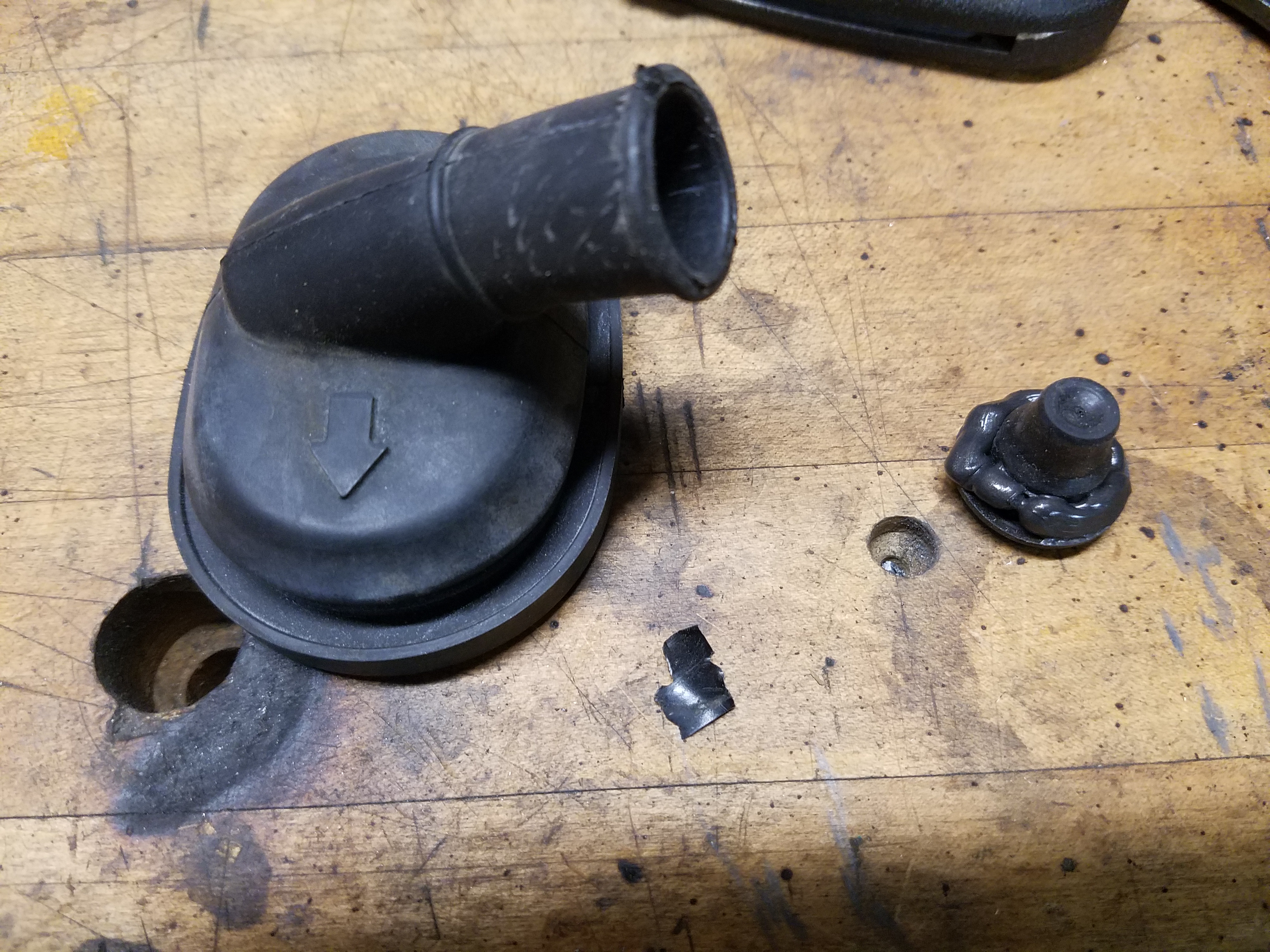
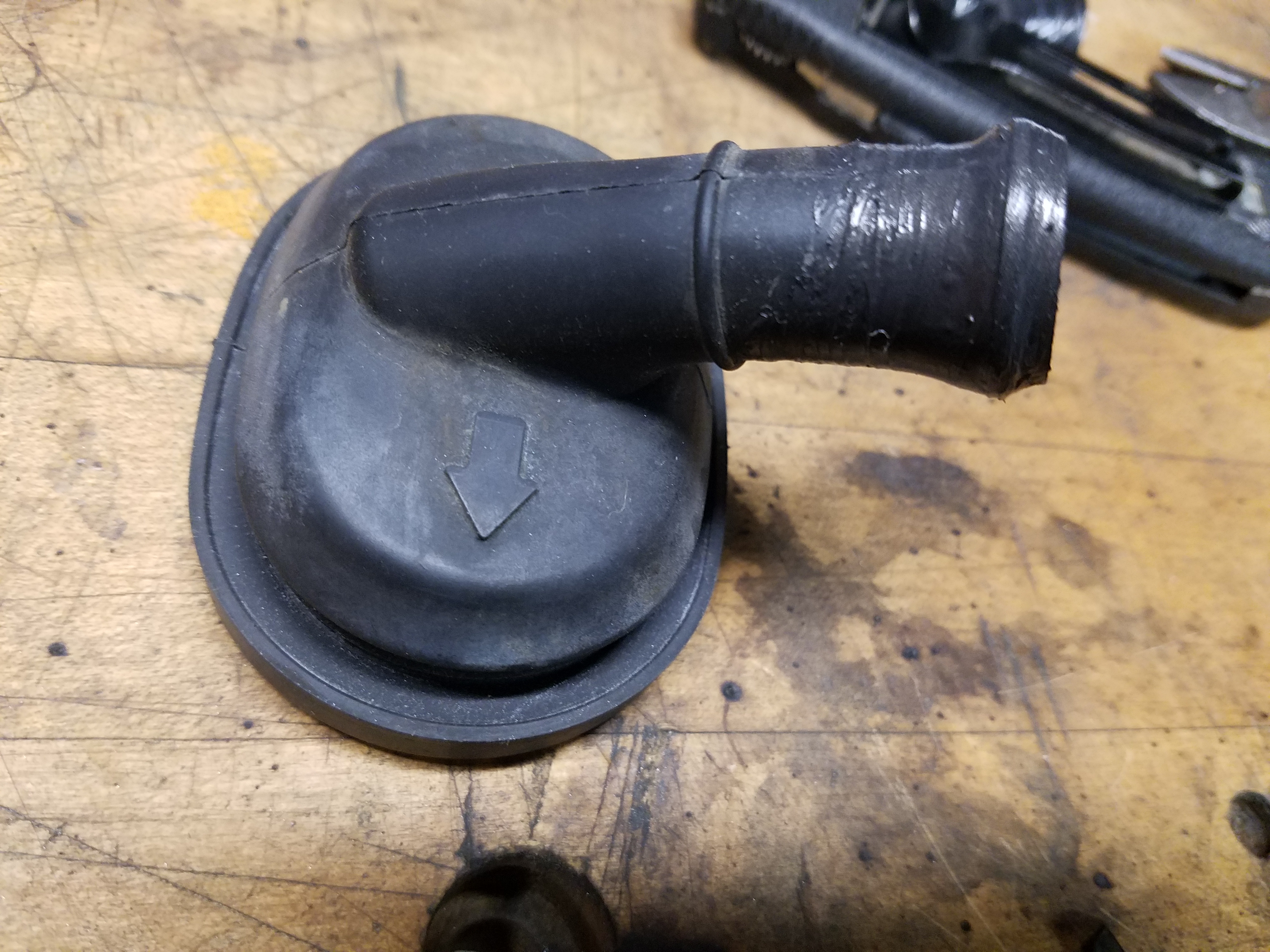
Also I rerouted the rubber line for the windshield washers. Since my new reservoir is on the driver's side, I just flipped the hose routing to the other side of where it mounts to the hood and trimmed the rubber line.
This post DIY: LS1 OBD2 Port Install - ClubRoadster.net was helpful in figuring this out. Basically you need to move the wire that carries the data connection to the PCM to pin 2.
You'll need to remove this white plastic piece from the back by just undoing a clip on one side and lifting it up
On my 99 Miata, the green/yellow wire was the data line which was located over on pin 7. In order to depin it just look at the pin from the front side of the connector and use a small pick to lift up the plastic tab I pointed to with the arrow.
Pull the wire from the back as you lift the tab and it should come out. Put it back on the pin 2 location so it should look like this from the back.
My CEL was related to both oxygen sensors having "no activity". It threw the code a few minutes after the engine was started, and I did verify the O2 sensors were both working fine when I started the car. I'll need to look into this a bit more and see if I have a bad connection. One of my sensors is new, the other is original to the engine.
I'm still having a cooling issue where the overflow tank goes from empty at startup to almost overflowing at full warm, the rad cap starts to emit steam. All the hoses are getting warm so I'm thinking the thermostat is opening. But I wasn't getting any heat from the hvac system. My fans were also not kicking on at any point.
My tach is reading about double the RPM of the engine speed. I'm not using a resistor as Flyin Miata describes, but I have one so I think I'll need to install it.
Did a couple small jobs like make a plug for the firewall hole previously was used for the engine harness. Just found a rubber plug and coated in some RTV and let it set.
Also I rerouted the rubber line for the windshield washers. Since my new reservoir is on the driver's side, I just flipped the hose routing to the other side of where it mounts to the hood and trimmed the rubber line.
Last edited by pj_mcgarvey; 03-21-2017 at 06:21 AM.
03-13-2017, 09:44 AM
#130
V8 Miata Enthusiast
Thread Starter
As I near the end of the build, the problems seem to be mounting.
1. I think I'm going to try a manual belt tensioner vs. the OEM spring-loaded one that seems to be moving quite a bit. For track cars, it would seem this would be the way to go anyway: Billet Belt Tensioner ? Katech Performance Online Store
2. I'm not convinced the DIY power steering pump bracket will hold up to long-term use/abuse. After putting some torque on the tensioner it seems the PS pump bracket moves a bit too. It's only mounted in two places vs the ideal 3 mount points (triangulated). Going to give Turn One a call and see about the CTS-V pump with the restrictor for Mazda flow rates.
3. After some OBD scans it seems my car is not going into closed loop. The o2 sensors are tripping a CE light a few minutes into the car warming up. I'm going to check the o2 sensor heater connection for 12v+ or ground issues. Car seems to run great otherwise.
4. With the Flyin Miata tachometer resistor fix the RPM is still double what it should be. Hmmm.
5. Not entirely sure my cooling system is filled, I have my doubts.
6. Fans are not kicking on so need to check wiring there.
We are getting 18" of snow over the next day or two and temps are almost single digits.
Fun fun fun.
Last edited by pj_mcgarvey; 03-29-2017 at 07:29 PM.
 03-13-2017, 10:35 AM
#132
V8 Miata Follower

I cant help with much else, but as for #6. I noticed the same problem during my first warmup cycle.
I verified my wiring was correct by providing 12v signal to the relays, and the fans came on, so I knew the PCM was not triggering them.
Now, I dont know if you guys are using HP Tuners. But I had to go into the tune and make some changes to the fan settings.
I will try and grab a screenshot this week of my exact settings. But for some reason , the PCM wants to verify AC refrigerant pressure before triggering the fans on. I had to play with a couple things, as well as tell the PCM what type of fan setup I was using for it to work (ie single fan, dual fan, single fan dual speed etc. ). After that, everything worked as it should.
All is not lost!
03-13-2017, 10:37 AM
#133
V8 Miata Follower
Also, for #4, did you wire the resistor in PARALLEL with the GAUGE? I know some people were having issues with that due to some misleading wording on that install. The resistor should not be in series with the signal, but in parallel to get gauge iirc.
03-13-2017, 12:46 PM
#134
V8 Miata Enthusiast
Thread Starter
Flyin Miata:
"The Miata tachometer is expecting a different voltage input than the GM ecu puts out, so we need to fool it. A 2200 ohm (2.2K) resistor needs to be jumpered in between switched 12 volts (Mazda 12v wire listed below) and the tachometer input lead (white wire in GM bulkhead connector) going from the GM harness to the Mazda instrument cluster.
The white GM wire will connect to the Mazda tach wire going in to your instrument cluster (below). The 12v -> 2200 ohm resistor -> will �T� into this tach wire. An easy way to visualize it is to just think of the 2200 ohm resistor as a jumper wire between the 12v wire and the tach wire where it plugs into the instrument cluster. Make sure you cover the resistor with heat shrink tubing to protect it from shorting! What you�re doing here is �pulling up� the tach signal voltage so the Mazda tach can read it.
� 90-93: 12v is 2K black/yellow, tach is 1H yellow/blue.
� 94-97: 12v is 2K black/yellow, tach is 1H black/white.
� 99-05: 12v is 1C black/yellow, tach is 2K green/orange."
The mention of the white GM wire is a bit confusing, when below that they describe three different color combinations for the tach wire.
What I've read is that when the RPM is double, it's because the tach is seeing twice as many engine rotation signals as it should, or a different frequency to put it another way. I'm not sure how a voltage strength change would alter that though. Maybe the resistor is intended to fix a different problem altogether?
Anyway, this Baker Electronix - Tachometer Adapterwould fix it for $40 but they are not shipping until 3/27, so not sure if I want to wait two more weeks, or go for this Universal Tachometer Signal Interface for twice the money.
03-13-2017, 12:51 PM
#135
V8 Miata Follower
I would prefer a picture to go along with Flyin Miata's description, but I think it's pretty clear when they say to "tee" into the tach wire. Unless their description is actually wrong, I think I have it right. Maybe some testing with a multimeter would confirm it.
Flyin Miata:
"The Miata tachometer is expecting a different voltage input than the GM ecu puts out, so we need to fool it. A 2200 ohm (2.2K) resistor needs to be jumpered in between switched 12 volts (Mazda 12v wire listed below) and the tachometer input lead (white wire in GM bulkhead connector) going from the GM harness to the Mazda instrument cluster.
The white GM wire will connect to the Mazda tach wire going in to your instrument cluster (below). The 12v -> 2200 ohm resistor -> will “T” into this tach wire. An easy way to visualize it is to just think of the 2200 ohm resistor as a jumper wire between the 12v wire and the tach wire where it plugs into the instrument cluster. Make sure you cover the resistor with heat shrink tubing to protect it from shorting! What you’re doing here is “pulling up” the tach signal voltage so the Mazda tach can read it.
• 90-93: 12v is 2K black/yellow, tach is 1H yellow/blue.
• 94-97: 12v is 2K black/yellow, tach is 1H black/white.
• 99-05: 12v is 1C black/yellow, tach is 2K green/orange."
The mention of the white GM wire is a bit confusing, when below that they describe three different color combinations for the tach wire.
What I've read is that when the RPM is double, it's because the tach is seeing twice as many engine rotation signals as it should, or a different frequency to put it another way. I'm not sure how a voltage strength change would alter that though. Maybe the resistor is intended to fix a different problem altogether?
Anyway, this Baker Electronix - Tachometer Adapterwould fix it for $40 but they are not shipping until 3/27, so not sure if I want to wait two more weeks, or go for this Universal Tachometer Signal Interface for twice the money.
EDIT: Im an idiot, I wrote this in reference to the speedo.
I honestly dont think I did anything at all for the tach and it just worked? Ill have to go back and look at some of my pictures to remember which wire from the PCM I used.
03-13-2017, 12:57 PM
#136
V8 Miata Enthusiast
Thread Starter
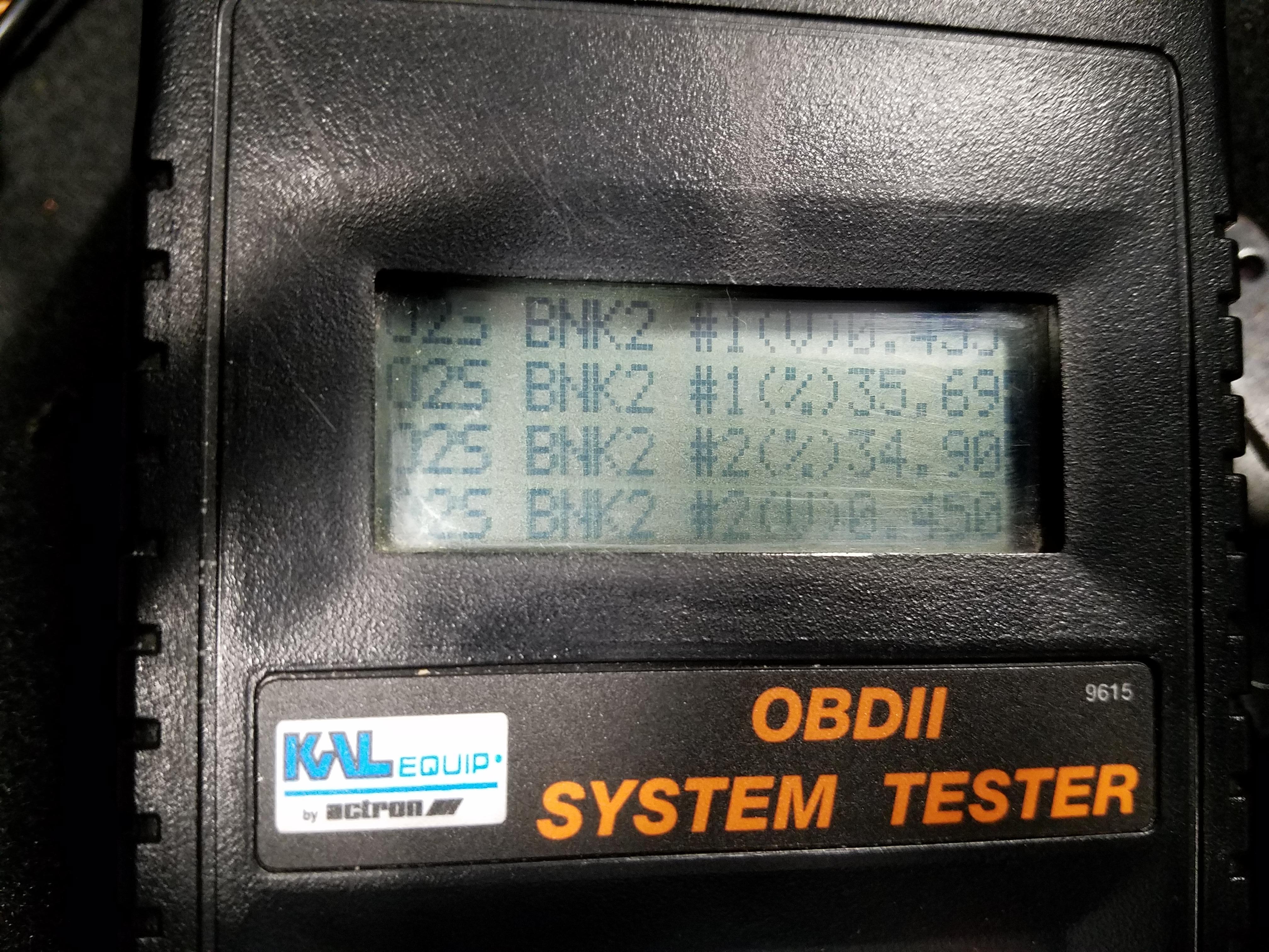
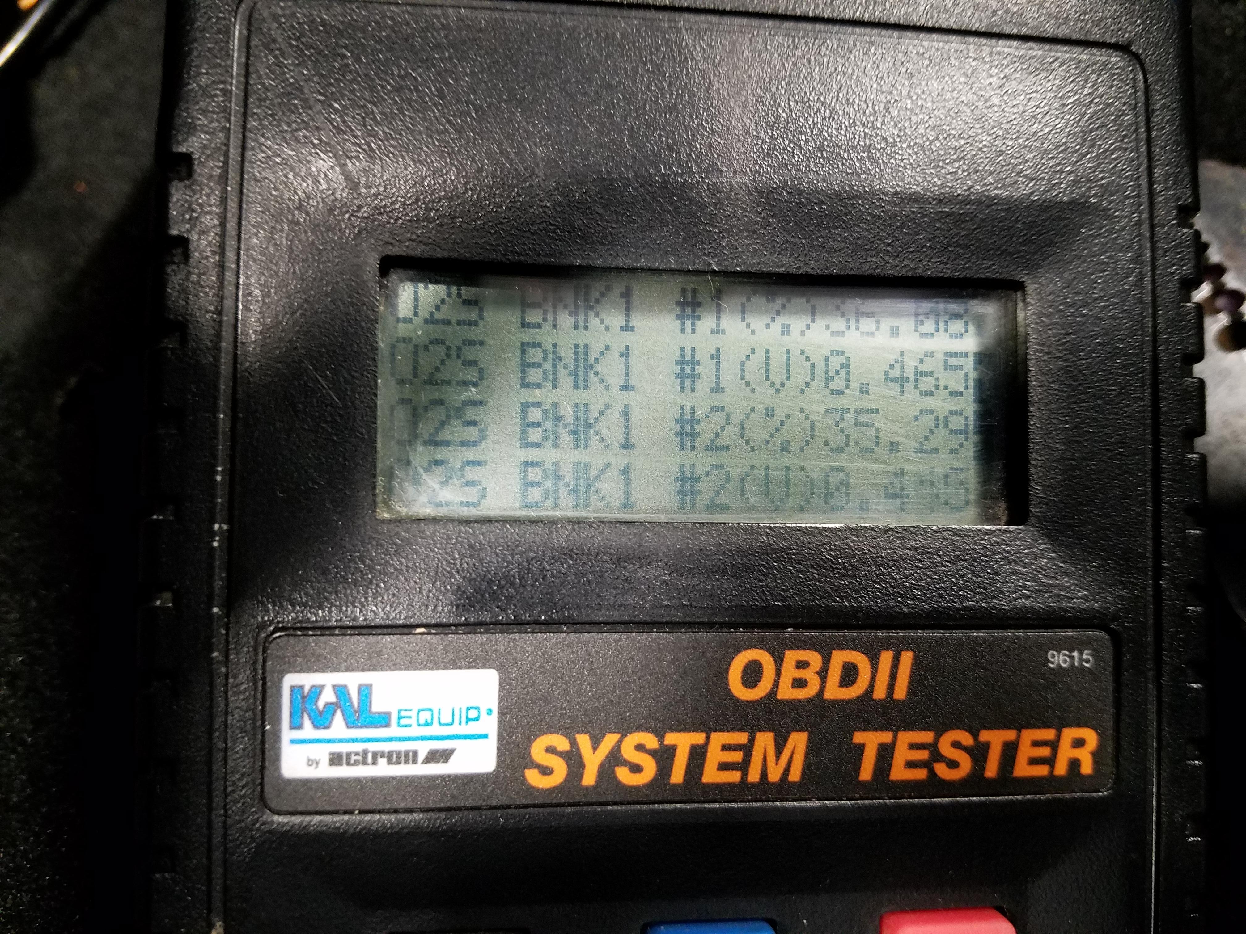
Thought I'd also share this bit of weirdness. My OBD scanner shows that I appear to have 4 O2 sensors, but I don't, I only have 2. Per the instructions on lt1swap.com when my PCM was sent to him for modifications, I should only be seeing readings from the front sensors (BNK1 #1 or BNK2 #1) as I just moved the wires for the rear sensors to the front pinouts. Rear pinouts are empty.
Is this typical behavior if one has had the rear sensors (BNK1 #2 or BNK2 #2) removed?
Edit: A buddy with an LS has the same symptoms as this, so I'm assuming it's normal, at least with the PCM programmer we both used.
Is this typical behavior if one has had the rear sensors (BNK1 #2 or BNK2 #2) removed?
Edit: A buddy with an LS has the same symptoms as this, so I'm assuming it's normal, at least with the PCM programmer we both used.
Last edited by pj_mcgarvey; 03-29-2017 at 07:31 PM.
03-13-2017, 01:11 PM
#139
V8 Miata Follower
What year LS PCM? I am using a '99 cluster if I remember correctly. I read somewhere that you only need the pull-up resistor if its a 2003+ PCMs
Alternatively, you should be able to scale the tach output with software. But I suppose that doesnt do you much good.
Alternatively, you should be able to scale the tach output with software. But I suppose that doesnt do you much good.
03-13-2017, 01:24 PM
#140
V8 Miata Enthusiast
Thread Starter
It's a 98 PCM, and I did read about the later PCMs working out of the box.
My guess is that my PCM guy didn't read my instructions about what car it was going into or this might not be an issue.
My guess is that my PCM guy didn't read my instructions about what car it was going into or this might not be an issue.
03-22-2017, 08:28 AM
#141
V8 Miata Enthusiast
Thread Starter
I went with a manual tensioner from KaTech, which seems to be doing the job quite well. Very nicely built piece, easy to adjust, looks good.
Billet Belt Tensioner ? Katech Performance Online Store
I'm also going with a different power steering pump, from the CTS-V, which is a pretty common choice among swappers. Turn One steering was nice enough to take allow me to return the F-Body pump I was using, which had very little actual use, just a few minutes idling. They will charge me a restocking fee, but the refund should work to about the same or more than I would get for the pump on the used market. New pump should ship this week I hope. I have the necessary parts for the pump coming to me as well, which would be the mounting bracket, reservoir, cap and rubber feed line.
I have the used but in new condition aluminum Turn One FBody pump pulley wheel for sale, if anyone is interested before I post it for sale.
My take on the OBD scan codes are that b/c I'm not driving the car or putting it through a drive cycle within a certain amount of time after starting the car up (for the first time) the PCM is telling me that something is wrong. So I'll have to see if the code reappears after I take the car for a drive. I verified the o2 sensor heater circuit is working, wiring is good, etc.
My cooling fans are working, I just had to wait until the LS temp sensor hit 200F before they kicked on. Yay.
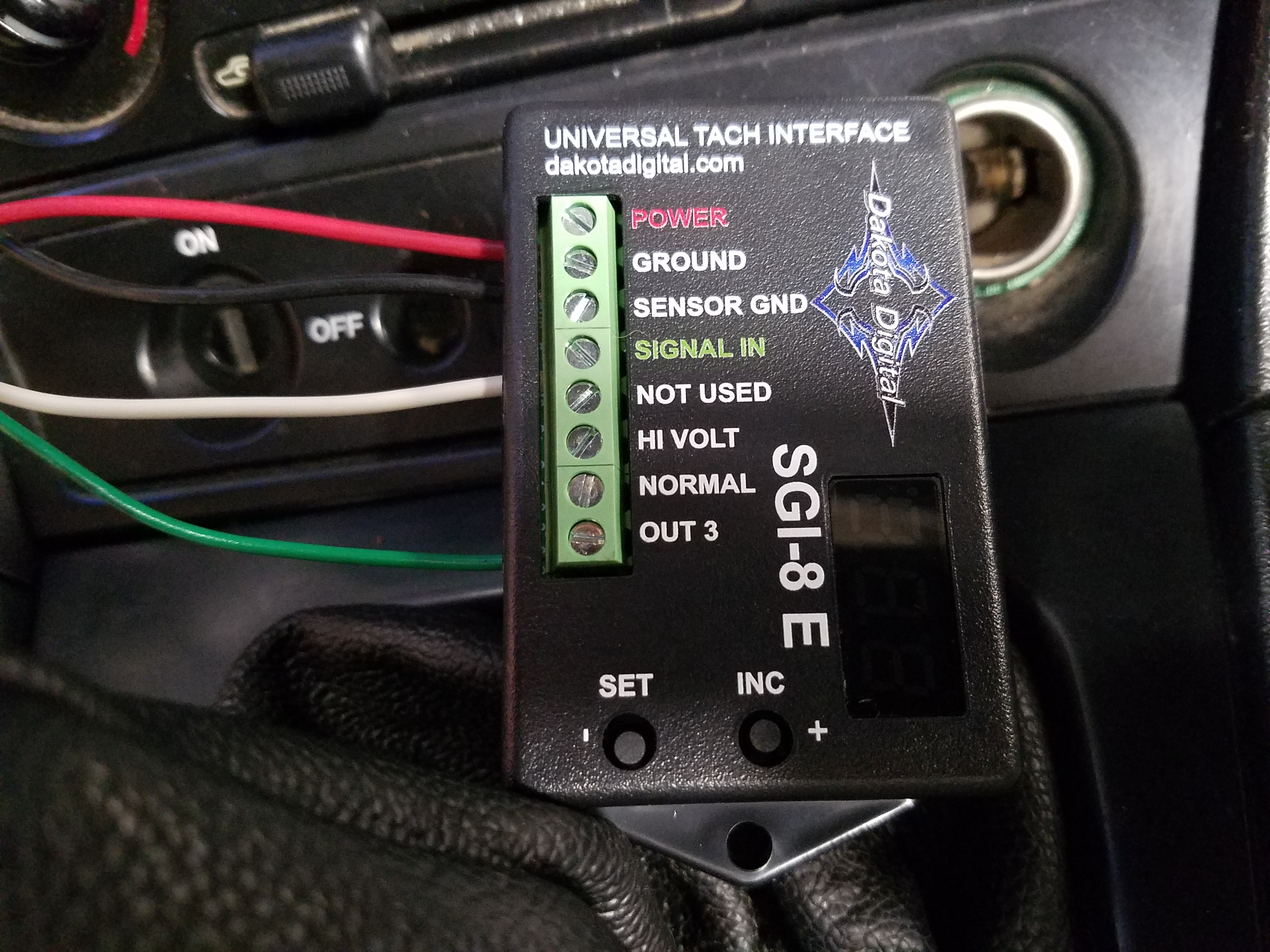
I've ordered a Dakota Digital module to fix the tachometer being off, should arrive tomorrow. http://www.dakotadigital.com/index.c...127/prd127.htm Good thing is I can just borrow or T off the power and ground wires I'm using for the Dakota speedometer module and just tuck them behind the instrument panel.
Other options to fix the tach signal would be http://www.bakerelectronix.com/products_tsd/ The "1/2 multiplier" TSD would fix a tach signal showing double the correct RPM. Baker Electronix isn't shipping til next week so I passed on waiting for that unit, though it would be cheaper.
In other news, my new wheels/tires arrived and look amazing. These are 15x9 949 Racing 6ULs in Tungsten. I ordered them from Flyin Miata prefitted with Toyo Proxes R1R 225/45ZR15. I think it was a good deal, and I also don't need to make the extra trips to get the tires mounted if I bought them separately.
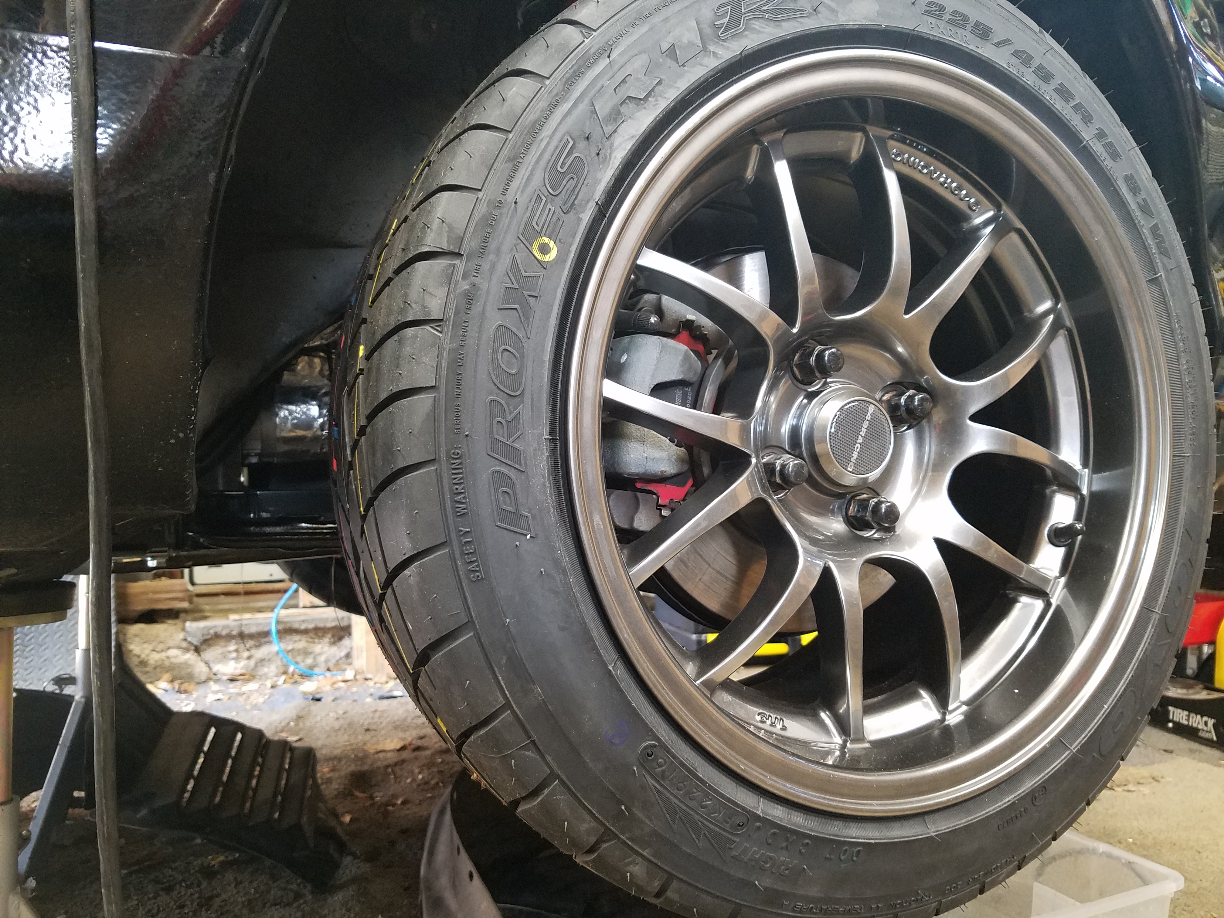
Next to my 15x6.5 Silver 6ULs. Makes the silver ones look kind of boring now. I hope in the daylight they will really "pop".
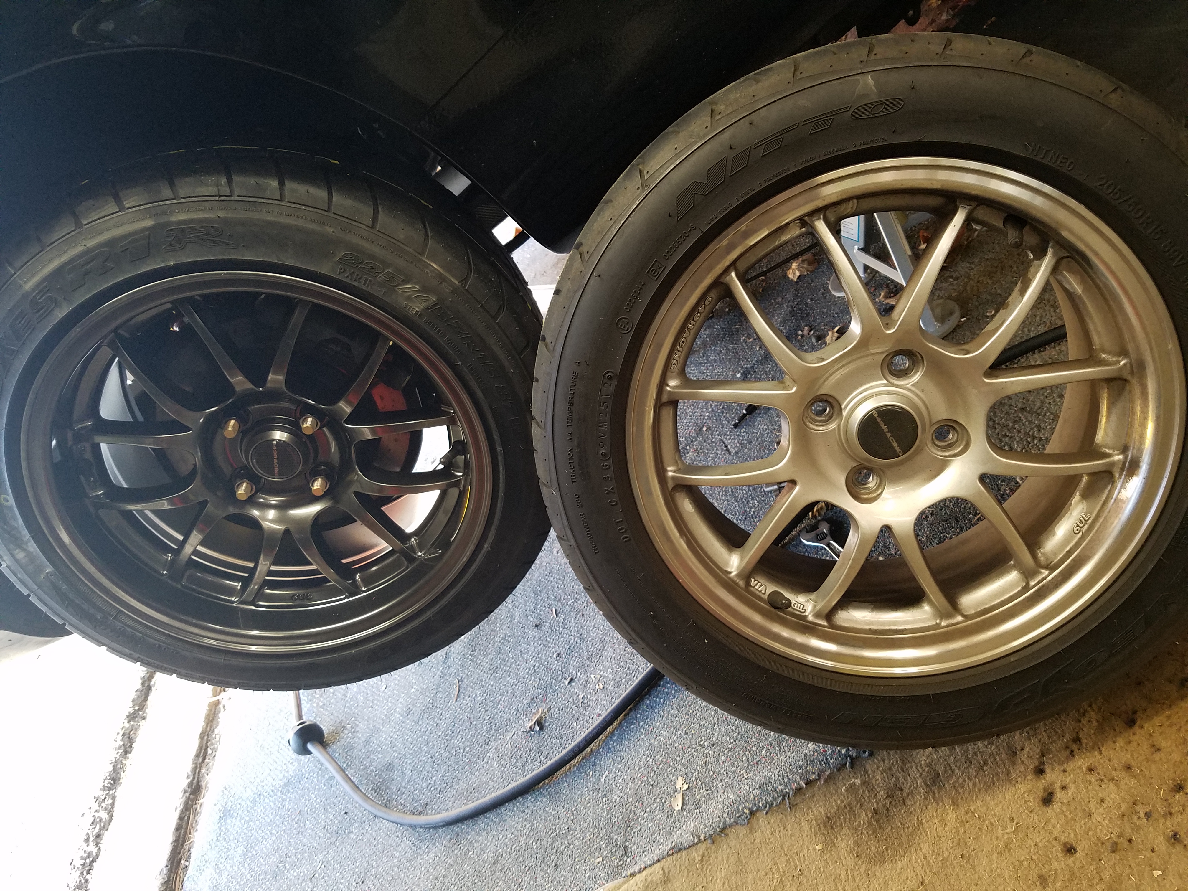
I had to cut the caps off my lug nuts for the rear as the wheel studs were too long. Might need to invest in some new lug nuts as mine are showing a bit of rust and look downright nasty next to these new wheels.
Also bought some exhaust tips to use, though I'm going to wait to make sure I like the mufflers enough before I put the work in to fit them.
They are from Flowmaster
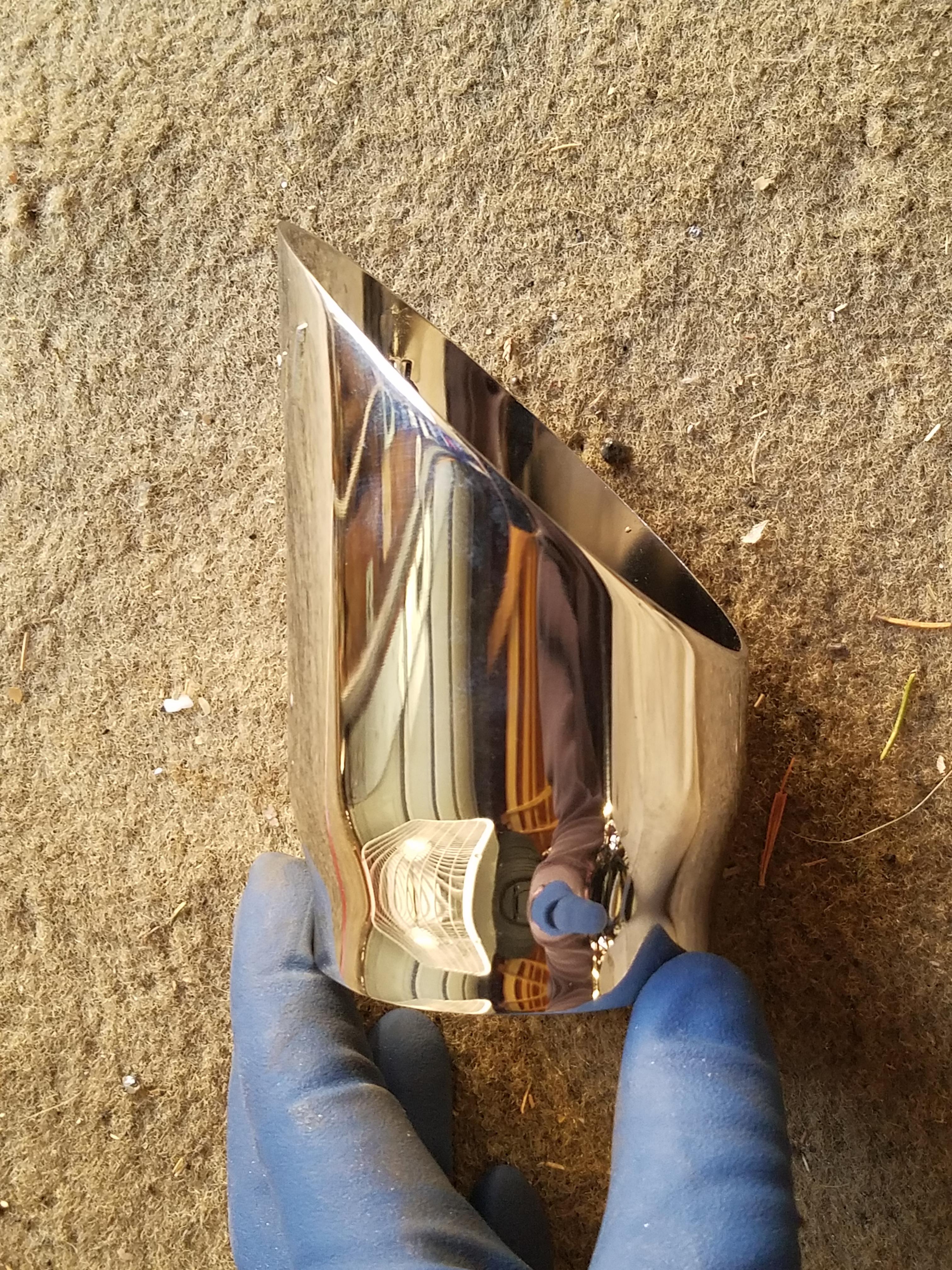
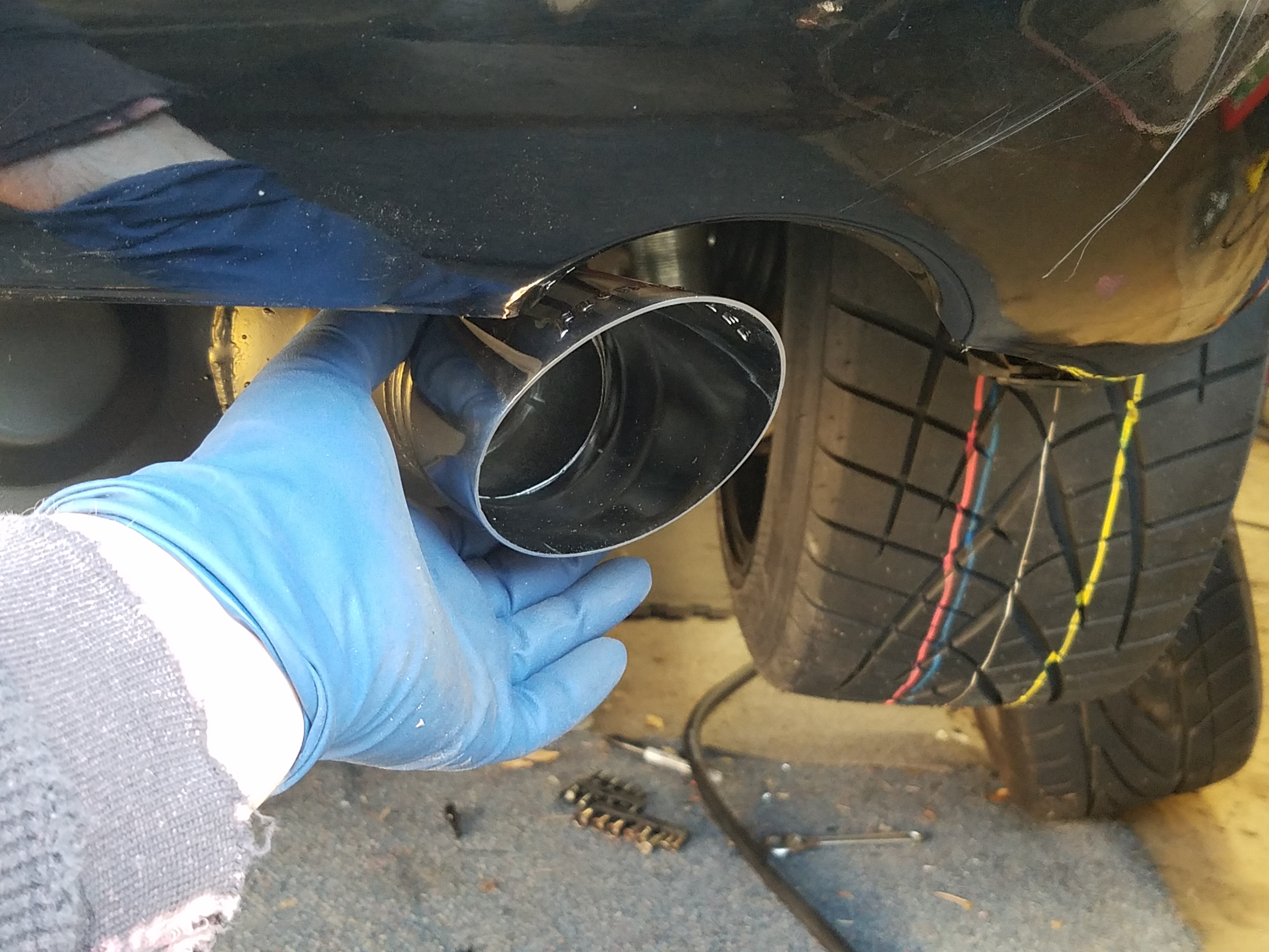
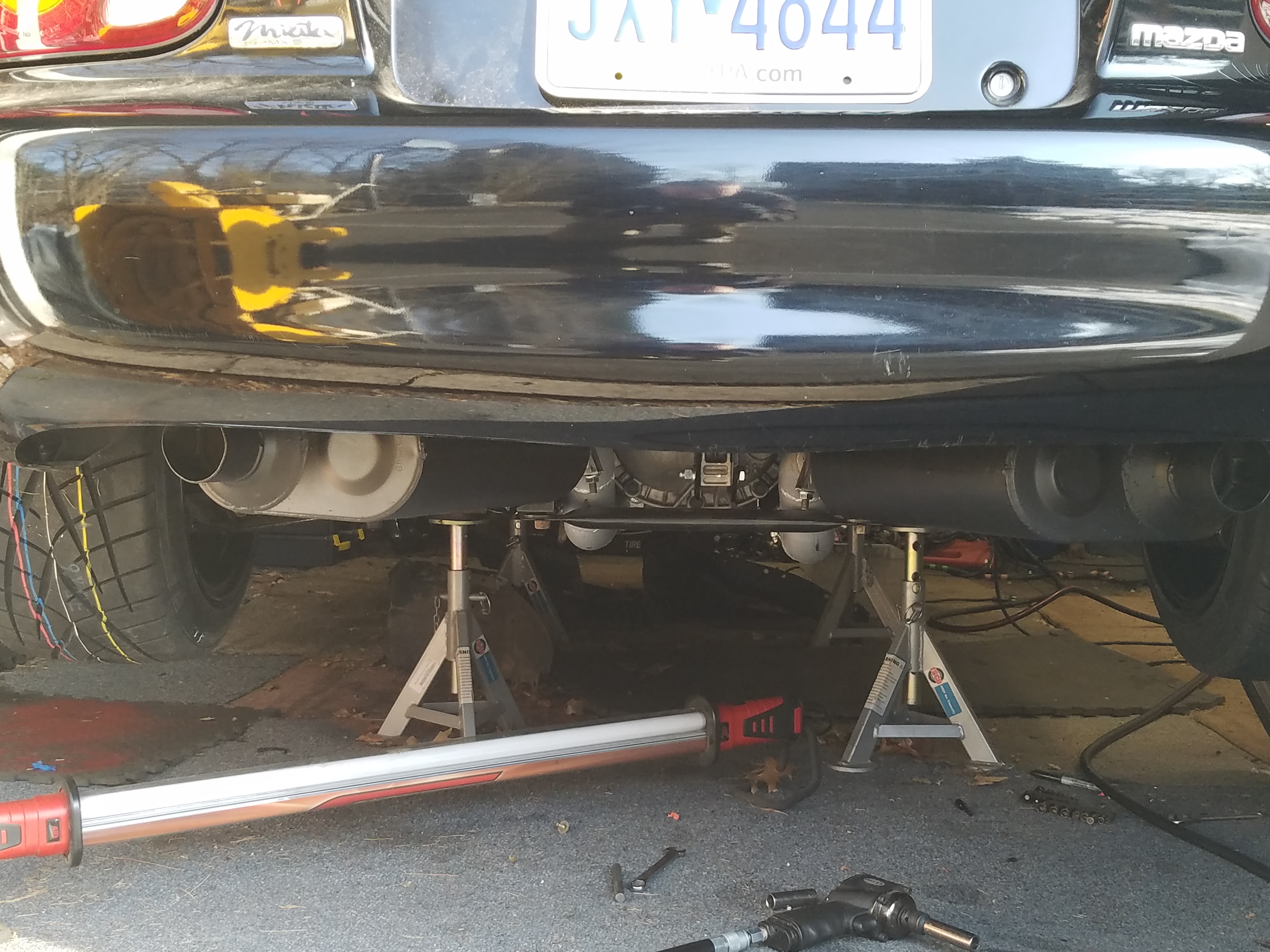
I think I'm going to go commando with the rear exhaust for now. I still need to fab up the hangers for the rear mufflers before I take it out for a drive.
Billet Belt Tensioner ? Katech Performance Online Store
I'm also going with a different power steering pump, from the CTS-V, which is a pretty common choice among swappers. Turn One steering was nice enough to take allow me to return the F-Body pump I was using, which had very little actual use, just a few minutes idling. They will charge me a restocking fee, but the refund should work to about the same or more than I would get for the pump on the used market. New pump should ship this week I hope. I have the necessary parts for the pump coming to me as well, which would be the mounting bracket, reservoir, cap and rubber feed line.
I have the used but in new condition aluminum Turn One FBody pump pulley wheel for sale, if anyone is interested before I post it for sale.
My take on the OBD scan codes are that b/c I'm not driving the car or putting it through a drive cycle within a certain amount of time after starting the car up (for the first time) the PCM is telling me that something is wrong. So I'll have to see if the code reappears after I take the car for a drive. I verified the o2 sensor heater circuit is working, wiring is good, etc.
My cooling fans are working, I just had to wait until the LS temp sensor hit 200F before they kicked on. Yay.
I've ordered a Dakota Digital module to fix the tachometer being off, should arrive tomorrow. http://www.dakotadigital.com/index.c...127/prd127.htm Good thing is I can just borrow or T off the power and ground wires I'm using for the Dakota speedometer module and just tuck them behind the instrument panel.
Other options to fix the tach signal would be http://www.bakerelectronix.com/products_tsd/ The "1/2 multiplier" TSD would fix a tach signal showing double the correct RPM. Baker Electronix isn't shipping til next week so I passed on waiting for that unit, though it would be cheaper.
In other news, my new wheels/tires arrived and look amazing. These are 15x9 949 Racing 6ULs in Tungsten. I ordered them from Flyin Miata prefitted with Toyo Proxes R1R 225/45ZR15. I think it was a good deal, and I also don't need to make the extra trips to get the tires mounted if I bought them separately.
Next to my 15x6.5 Silver 6ULs. Makes the silver ones look kind of boring now. I hope in the daylight they will really "pop".
I had to cut the caps off my lug nuts for the rear as the wheel studs were too long. Might need to invest in some new lug nuts as mine are showing a bit of rust and look downright nasty next to these new wheels.
Also bought some exhaust tips to use, though I'm going to wait to make sure I like the mufflers enough before I put the work in to fit them.
They are from Flowmaster
I think I'm going to go commando with the rear exhaust for now. I still need to fab up the hangers for the rear mufflers before I take it out for a drive.
03-22-2017, 09:06 AM
#143
V8 Miata Enthusiast
Thread Starter
Thanks. Based on my research, it should fit an NB Miata with very little fender rubbing. I bought a fender roller so I should have no issues, but I won't know til I get the car on the ground and set the ride height and drive it.
There is a bit of tire stretch with this tire on a 15x9, but Flyin Miata approved, and others have no issues. If over time there are no issues, I might move to a 235 or 245 on the rear for more grip. We will see.
Front sway bar clearance might be an issue if you are using certain bars. I don't think I will, but I have heard of others.
03-24-2017, 08:06 AM
#144
V8 Miata Enthusiast
Thread Starter
The Dakota Digital Tach interface did the trick to fix the RPM. Here's how I wired it. OUT3 halves the signal which worked fine for me, the other outputs can be adjusted up or down in increments. Very nice piece with clear instructions.
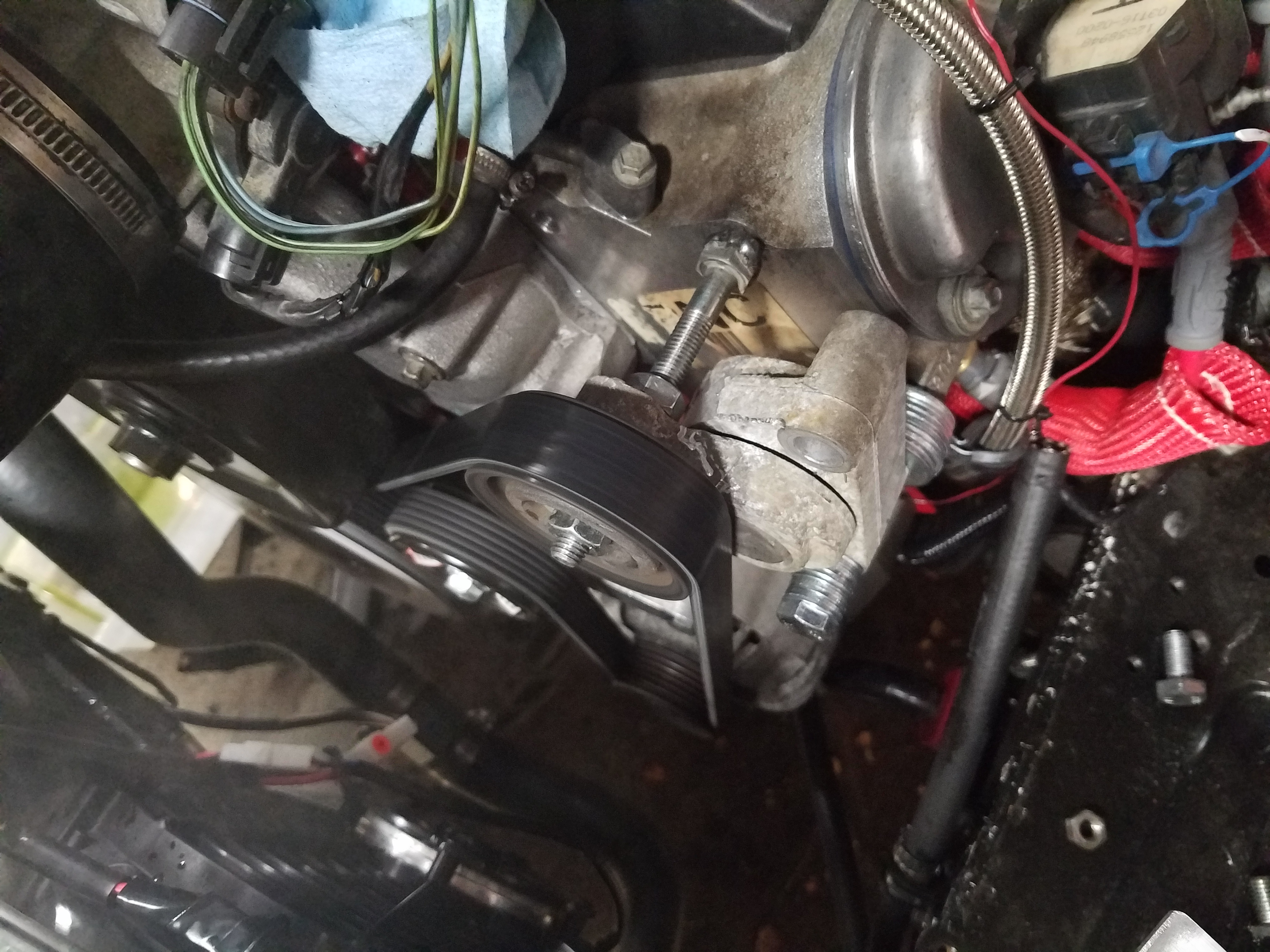
Since I don't have my new power steering pump yet, and I sent the other one back for a refund, and I wanted to idle the car to test things out, I made a quick pulley out of the old water pump tensioner I pulled off the engine when I bought it. Guess it pays to keep old junk around.
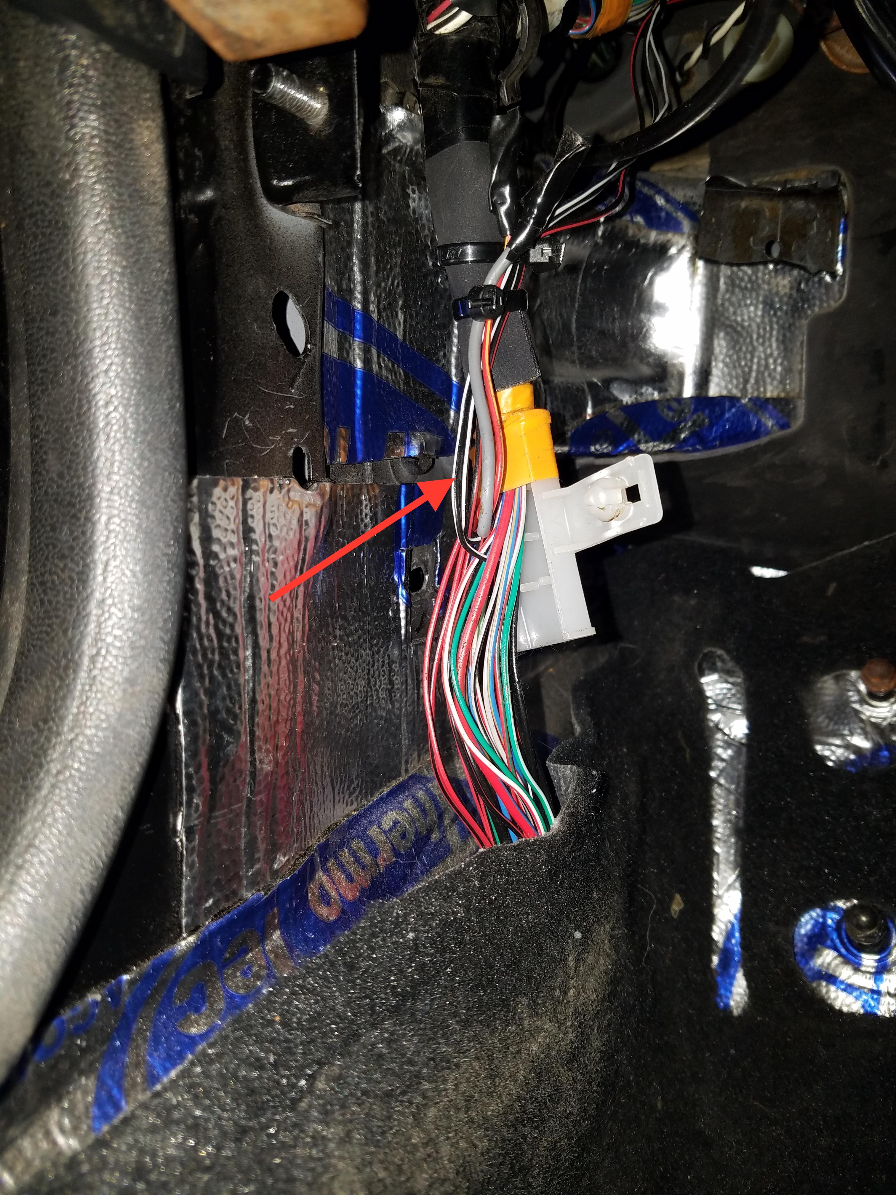
Here's a quick pic of the Miata wire I used to grab 12v power for the O2 sensors. Just two black/white wires near the driver's side left foot. The wire normally goes under the driver's seat and through a grommet in the tunnel to the rear O2 sensor on the stock Miata exhaust. I just routed it back up behind the dash and split it off to each front LS1 sensor. It's already fused in the Miata fuse box.
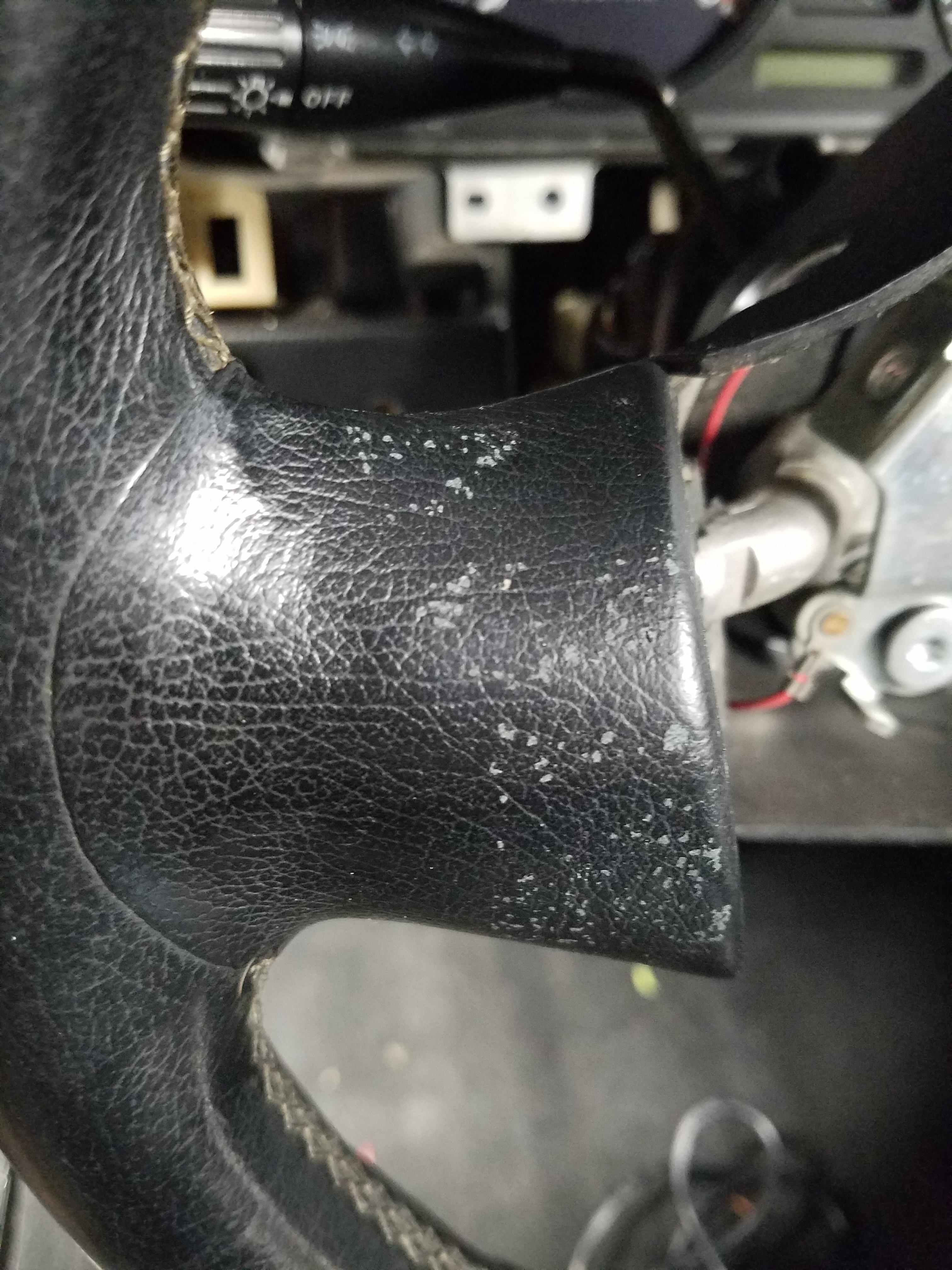
Unfortunately my Miata Nardi airbag wheel got some damage in storage. I had used blue painter's tape to hold the airbag module to the wheel, but when I removed the tape it took some of the "leather" with it. This is before I tried some leather conditioner on it, so I'll have to see about what I can do to fix or hide this.
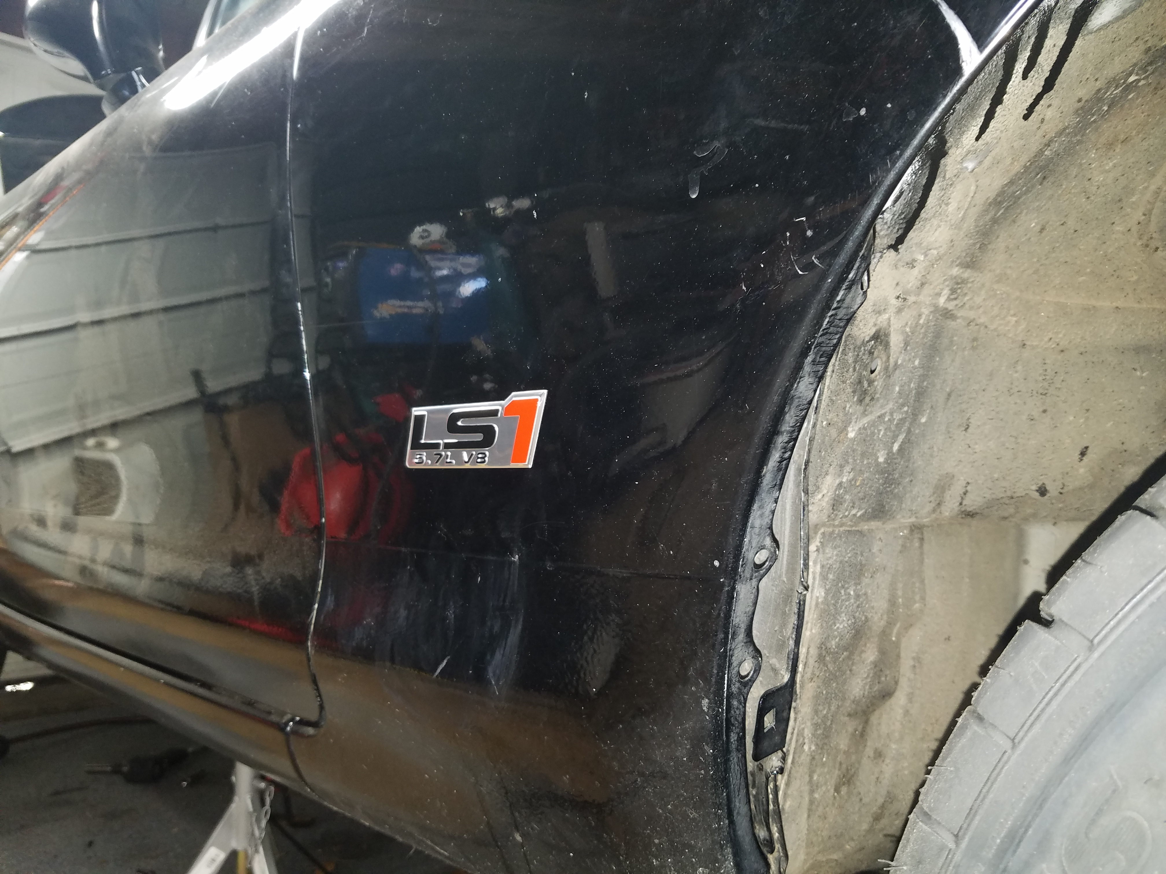
Finally, I had been waiting to do this little mod, and it seemed like the right time. Got these from Amazon for a song, one for each side. Comes with adhesive backing. They were a bit big to put on the back of the car, so I went with the side. Guess that removes any guesswork about what engine's in the car. Stealth be gone!
Hoping to put the car on the ground and pull it out of the garage this weekend. I have 100 ft. long driveway, so may just do some testing of gearbox, brakes, set ride height, and rough set the alignment. Once I have the PS pump I should be able to take it for a test drive.
Since I don't have my new power steering pump yet, and I sent the other one back for a refund, and I wanted to idle the car to test things out, I made a quick pulley out of the old water pump tensioner I pulled off the engine when I bought it. Guess it pays to keep old junk around.
Here's a quick pic of the Miata wire I used to grab 12v power for the O2 sensors. Just two black/white wires near the driver's side left foot. The wire normally goes under the driver's seat and through a grommet in the tunnel to the rear O2 sensor on the stock Miata exhaust. I just routed it back up behind the dash and split it off to each front LS1 sensor. It's already fused in the Miata fuse box.
Unfortunately my Miata Nardi airbag wheel got some damage in storage. I had used blue painter's tape to hold the airbag module to the wheel, but when I removed the tape it took some of the "leather" with it. This is before I tried some leather conditioner on it, so I'll have to see about what I can do to fix or hide this.
Finally, I had been waiting to do this little mod, and it seemed like the right time. Got these from Amazon for a song, one for each side. Comes with adhesive backing. They were a bit big to put on the back of the car, so I went with the side. Guess that removes any guesswork about what engine's in the car. Stealth be gone!
Hoping to put the car on the ground and pull it out of the garage this weekend. I have 100 ft. long driveway, so may just do some testing of gearbox, brakes, set ride height, and rough set the alignment. Once I have the PS pump I should be able to take it for a test drive.
03-24-2017, 08:15 AM
#145
V8 Miata Enthusiast
Thread Starter
Couple questions for anyone listening:
- Does anyone have short lengths of header wrap they would like to sell me? I need to wrap about 8" or so of the 2.5" header where it transitions to my exhaust system that I couldn't cover with the wrap I had bought. I'm not sure exactly how much I need but was wondering if anyone had more than they needed?
- What are people doing for oil temp sensors? I had a temp sensor mounted as the oil drain plug on the Miata engine, and I don't feel like tapping the pan right now for a sensor. Is anyone using the oil pressure sender hole to make an adapter for the oil pressure and temperature? I've done some searching, but figured I'd ask here.
03-25-2017, 05:16 PM
#146
V8 Miata Enthusiast
Thread Starter
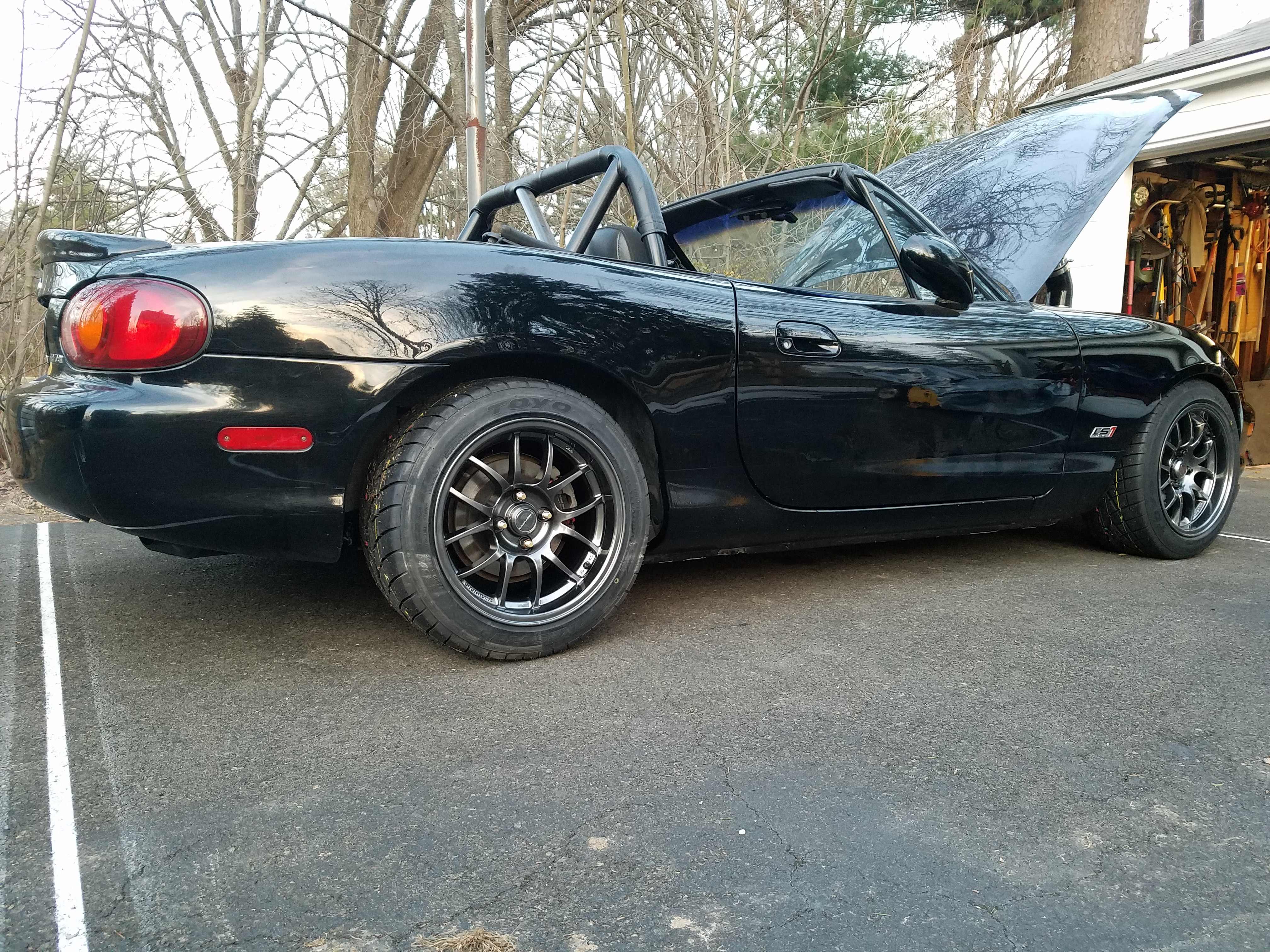
The car moves under its own power and sees daylight for the first time in 7 months.
It was obvious the front ride height was too low, and the front VMaxx coilovers were at their max ride height. This would be obvious when you consider the extra weight on the front of the car with the LS engine. Turns out FM sells a specific spring for this problem https://www.flyinmiata.com/fm-v8-v-m...nt-spring.html Order placed.
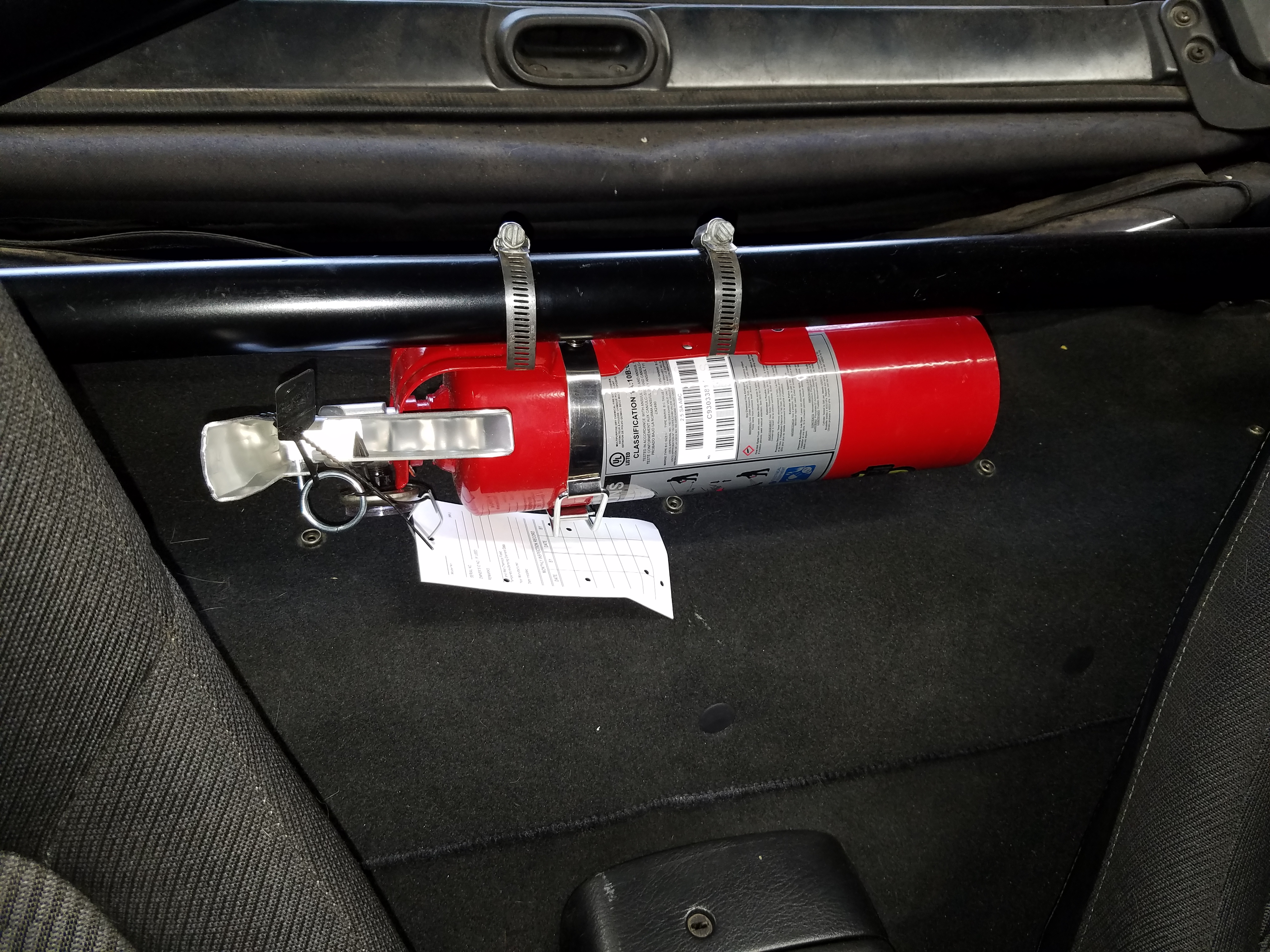
Installed a fire extinguisher, the harness bar on the roll bar makes for a pretty good location. This is a project car and will see some track work, so better safe than sorry.
Hoping this time next weekend the car will be ready for it's first test drive.
It was obvious the front ride height was too low, and the front VMaxx coilovers were at their max ride height. This would be obvious when you consider the extra weight on the front of the car with the LS engine. Turns out FM sells a specific spring for this problem https://www.flyinmiata.com/fm-v8-v-m...nt-spring.html Order placed.
Installed a fire extinguisher, the harness bar on the roll bar makes for a pretty good location. This is a project car and will see some track work, so better safe than sorry.
Hoping this time next weekend the car will be ready for it's first test drive.
Last edited by pj_mcgarvey; 03-26-2017 at 01:52 PM.
 03-27-2017, 09:51 PM
#148
V8 Miata Fanatic


Coming together nicely. I'm of little use to you in these last few posts with no header wrap or help with the tach and such. But, the V8M looks and sounds great! Keep the posts coming, it's fun watching you button things up.
03-28-2017, 08:51 PM
#149
V8 Miata Enthusiast
Thread Starter
Ah yes� wiring. The often feared, much maligned, misunderstood wiring. Mysterious electrons flowing over copper strand at the speed of light.
Anyway� there are some good guides out there for the Miata swaps, and some good �filler� info on ls swaps in general that helped me out.
Wiring guides:
Nathan�s site is NA Miata specific, but gives a good overview of the steps, including a summary of the harness mods:
Nathan's LS1 Miata
Flying Miata�s guide is laid out a bit better and has more specifics on one generation to the next:
http://www.flyinmiata.com%2Fsupport%...structions.pdf
LS PCM �pin out� guides:
Chevythunder - scroll down half way for pinout guides for various LS models:
LS1 97-98 specific pin out guide (what I used):
1997-98 LS1 PCM pinouts
LS1 guide to different engine components:
LS1 page 1
Brendan at LT1 Swap was who I used to reprogram my PCM. Their site also provides good info, similar to chevythunder.com. His guides give a good overview of the different options available for PCM programming if you are new to that.
1997 1998 Corvette Camaro Firebird PCM Pinouts
I would not recommend LT1Swap.com for any PCM work, I�m sure there are others who have had good experiences with him, and I did as well for what I was expecting. I would not say he is very good at timely communication or answering questions. It's possible he created some other problems for me in the mods he made, or didn't make, but it's hard to know b/c I can't inspect the PCM, and he has not replied to my questions in many weeks.
The wiring harness:
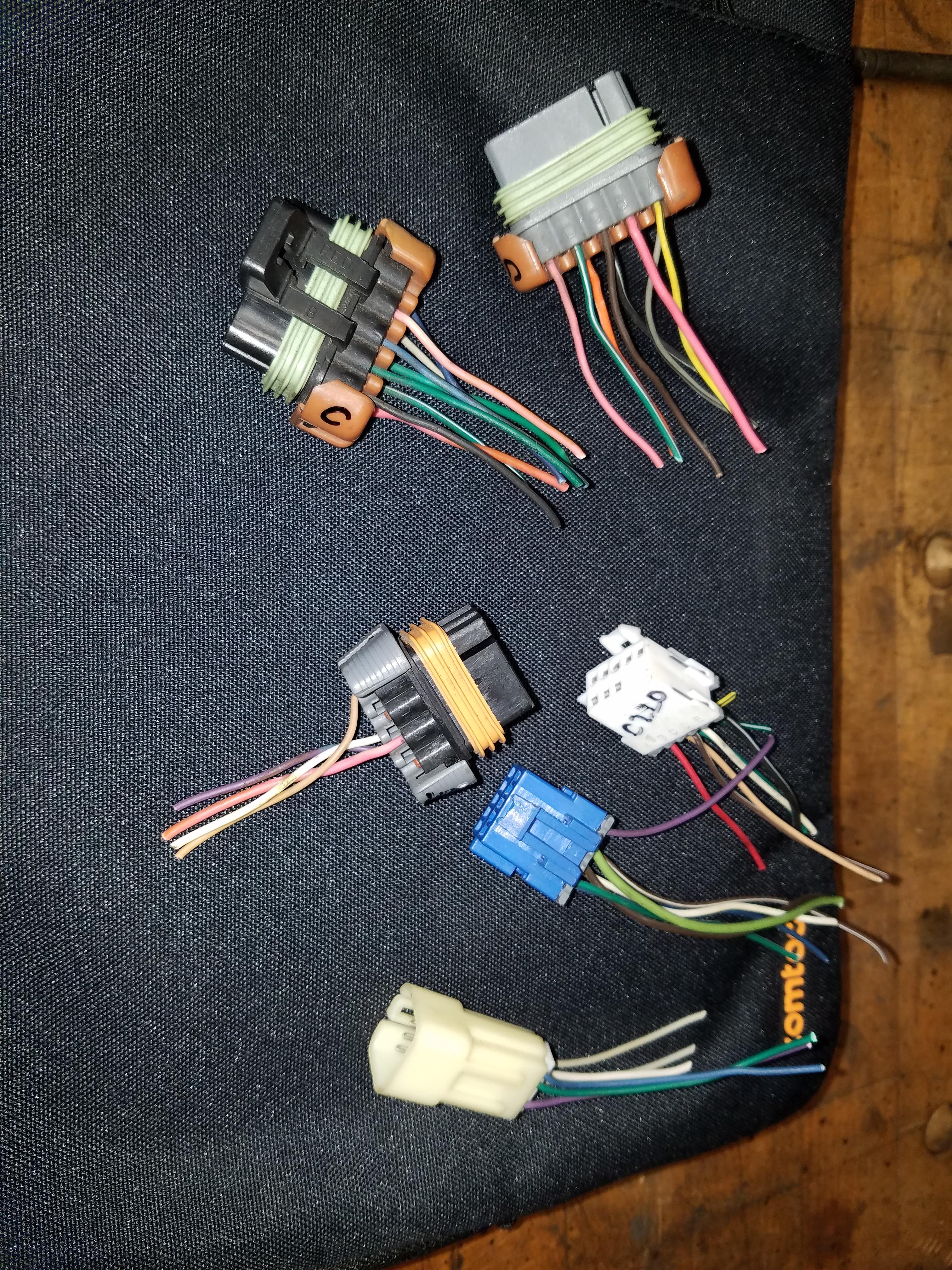
I found some open floor space in my finished basement to lay out the harness and start to pick over it, labeling each connector with what it does. I�d recommend a space where you know the kid/cat/dog etc. won�t get in your way, step on delicate connectors, or chew on those delicious wires.
The pictures here are a good guide to IDing each connector (download picture and zoom in)
Wiring information for 1998 to 2002 Camaro & Firebird LS1
This site has more of a DIY step by step guide on cleaning up a LS harness, with pictures:
http://www.thirdgen.org/forums/ltx-l...rt-finish.html
The two PDF files linked here were the most detailed at showing the connector locations on the engine and trans, and on the harness itself. Very helpful if you are unfamiliar with LS engines:
http://www.norotors.com/index.php?topic=175.0
You will want to think about what sensors or features you will not need. If you are using a manual transmission but have a harness from an auto trans car, you will remove connectors for an auto trans as there are a few more of them. If you are deleting EGR, remove those connectors by looking up the PIN numbers that relate to those sensors and remove them completely from the PCM. You can remove the whole wire from the PCM connector by de-pinning it and pulling it through. Youtube has some guides on how to depin the LS PCM, though you may be able to figure it out yourself.
Per the LT1Swap.com site, most swappers use only two o2 sensors, one for each bank of the engine. He suggests that you take the rear o2 sensor harness wires and connector and just move them to the front o2 sensor PCM pin locations. You can eliminate the rear sensors by turning them off in the PCM. Though in my experience they aren�t really removed - in my experience you will still see a rear sensor show up in the OBD scan output. It seems the PCM is just tricked into thinking the rear sensors have the same o2 signal as the front. If you see a function related to a specific pin on the diagrams, just google for the name and you can usually get an answer as to what it does and whether it is applicable to you.
PCM functions you may want:
* OBD port wires - connect to Miata OBD port (if applicable)
* MIL light - illuminate the CE light on the instrument panel
* Generator warning light - going to hook this up assuming it will work. FM guide says it should.
PCM functions you may NOT want:
* Auto trans related stuff - TCC switch, park neutral switch
* Oil level sensor - most will have removed the oil level sensor when switching to a custom oil pan
* CAGS - T56 skip shift function
* VATS - you will have VATS disabled most likely as the car will not start without it
* Rear 02 sensors - you will only need the front sensors for most applications
* Anything EGR related
Harness connectors:
Part of the main harness, aside from the engine sensor connectors, fuel injectors, coil packs, etc. are the Cxxx connectors or whatever you want to call them (C101, C105, C220, etc). These would have connected inside the car the harness came out of. These connectors were for getting fused/relayed power from the car to power the PCM and other engine functions. They may also feed signals from the engine/PCM back into the car for gauges, OBD, water temp gauge, or other things. I left these as is and labeled each one with a marker or masking tape.
This url shows which connector is which on the LS1. If you use google image search for the connector name and your engine, year, etc. you will find plenty of info:
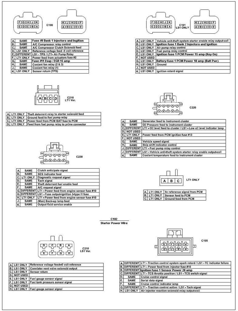
This url provided a good overview of harness modifications in general (the whole swap site has good info). I used the yellow boxes about halfway down the page �Connectors for 97-98 LS1 Engines�
LS SWAPS: Wiring Harness and Wiring Guide
The info above came from a book which is available free to read on Google Books, however many pages of the book here (for free) are not available on purpose, so be aware of that:
https://books.google.com/books?id=AP...cPC2YQ6AEIJTAA
If the link doesn�t work just search Google books for �How to Swap GM LS engines into almost anything�.
Anyway� there are some good guides out there for the Miata swaps, and some good �filler� info on ls swaps in general that helped me out.
Wiring guides:
Nathan�s site is NA Miata specific, but gives a good overview of the steps, including a summary of the harness mods:
Nathan's LS1 Miata
Flying Miata�s guide is laid out a bit better and has more specifics on one generation to the next:
http://www.flyinmiata.com%2Fsupport%...structions.pdf
LS PCM �pin out� guides:
Chevythunder - scroll down half way for pinout guides for various LS models:
LS1 97-98 specific pin out guide (what I used):
1997-98 LS1 PCM pinouts
LS1 guide to different engine components:
LS1 page 1
Brendan at LT1 Swap was who I used to reprogram my PCM. Their site also provides good info, similar to chevythunder.com. His guides give a good overview of the different options available for PCM programming if you are new to that.
1997 1998 Corvette Camaro Firebird PCM Pinouts
I would not recommend LT1Swap.com for any PCM work, I�m sure there are others who have had good experiences with him, and I did as well for what I was expecting. I would not say he is very good at timely communication or answering questions. It's possible he created some other problems for me in the mods he made, or didn't make, but it's hard to know b/c I can't inspect the PCM, and he has not replied to my questions in many weeks.
The wiring harness:
I found some open floor space in my finished basement to lay out the harness and start to pick over it, labeling each connector with what it does. I�d recommend a space where you know the kid/cat/dog etc. won�t get in your way, step on delicate connectors, or chew on those delicious wires.
The pictures here are a good guide to IDing each connector (download picture and zoom in)
Wiring information for 1998 to 2002 Camaro & Firebird LS1
This site has more of a DIY step by step guide on cleaning up a LS harness, with pictures:
http://www.thirdgen.org/forums/ltx-l...rt-finish.html
The two PDF files linked here were the most detailed at showing the connector locations on the engine and trans, and on the harness itself. Very helpful if you are unfamiliar with LS engines:
http://www.norotors.com/index.php?topic=175.0
You will want to think about what sensors or features you will not need. If you are using a manual transmission but have a harness from an auto trans car, you will remove connectors for an auto trans as there are a few more of them. If you are deleting EGR, remove those connectors by looking up the PIN numbers that relate to those sensors and remove them completely from the PCM. You can remove the whole wire from the PCM connector by de-pinning it and pulling it through. Youtube has some guides on how to depin the LS PCM, though you may be able to figure it out yourself.
Per the LT1Swap.com site, most swappers use only two o2 sensors, one for each bank of the engine. He suggests that you take the rear o2 sensor harness wires and connector and just move them to the front o2 sensor PCM pin locations. You can eliminate the rear sensors by turning them off in the PCM. Though in my experience they aren�t really removed - in my experience you will still see a rear sensor show up in the OBD scan output. It seems the PCM is just tricked into thinking the rear sensors have the same o2 signal as the front. If you see a function related to a specific pin on the diagrams, just google for the name and you can usually get an answer as to what it does and whether it is applicable to you.
PCM functions you may want:
* OBD port wires - connect to Miata OBD port (if applicable)
* MIL light - illuminate the CE light on the instrument panel
* Generator warning light - going to hook this up assuming it will work. FM guide says it should.
PCM functions you may NOT want:
* Auto trans related stuff - TCC switch, park neutral switch
* Oil level sensor - most will have removed the oil level sensor when switching to a custom oil pan
* CAGS - T56 skip shift function
* VATS - you will have VATS disabled most likely as the car will not start without it
* Rear 02 sensors - you will only need the front sensors for most applications
* Anything EGR related
Harness connectors:
Part of the main harness, aside from the engine sensor connectors, fuel injectors, coil packs, etc. are the Cxxx connectors or whatever you want to call them (C101, C105, C220, etc). These would have connected inside the car the harness came out of. These connectors were for getting fused/relayed power from the car to power the PCM and other engine functions. They may also feed signals from the engine/PCM back into the car for gauges, OBD, water temp gauge, or other things. I left these as is and labeled each one with a marker or masking tape.
This url shows which connector is which on the LS1. If you use google image search for the connector name and your engine, year, etc. you will find plenty of info:
This url provided a good overview of harness modifications in general (the whole swap site has good info). I used the yellow boxes about halfway down the page �Connectors for 97-98 LS1 Engines�
LS SWAPS: Wiring Harness and Wiring Guide
The info above came from a book which is available free to read on Google Books, however many pages of the book here (for free) are not available on purpose, so be aware of that:
https://books.google.com/books?id=AP...cPC2YQ6AEIJTAA
If the link doesn�t work just search Google books for �How to Swap GM LS engines into almost anything�.
Last edited by pj_mcgarvey; 05-25-2017 at 10:59 AM.
03-28-2017, 08:55 PM
#150
V8 Miata Enthusiast
Thread Starter
Installing Harness:
Once you�ve got your PCM location established (see an earlier post of mine to see what I did) and you have a working LS harness, my approach was to connect the harness to the PCM and bolt in both red and blue side connections, so it doesn�t pull out and damage the pins as you are tugging on the harness during install. It might be a good idea to make sure your battery is disconnected at this point, so your not sending power through the car or wiring by accident.
Lay the harness out on the engine and start making connections. For the most part this should be easy and satisfying - the positive click of a sensor connector going into place. This will start to give you an idea where the bulk of the harness will route. If you aren�t happy with it, you can con�t to pull it apart, extend or shorten wires, etc. to your preference.
I stripped off all electrical tape and plastic wire loom and used loose zip ties to keep things from getting out of control. Keep them loose so you can pull new wires through for later as you route things across the engine into the cabin.
First step was to make a good ground to the chassis by using an available bolt hole on the back of the driver�s side head. Connect the multiple black wire ground connections on the harness to this location with a ring terminal. Then add another 6-8 gauge connection from this bolt to the firewall or frame rail using the Miata locations.
On my car the 10 gauge (?) Black/Red cable that comes out near the Miata main fuse block, connects to the starter. The LS1 cable coming from the starter on my car was light purple, so I just connected those two securely with a crimp connector and weather seal.
Sidenote - For routing various things I�m using the corner of the engine bay on the passenger side, where you cut out the gussets early in your build, and where the tunnel, the firewall and engine bay frame rails meet. I have my fuel line, brake line and wires for the trans, o2 sensors, CKP (crank) sensor and starter connections going down here.
Power connections:
There are two orange wires in the LS1 harness that come out of the PCM, and then combine into one wire. This orange wire needs to be hot all the time so the PCM can retain its memory. I ran a wire with a 15A fuse through my own fuse block to the thick black wire from the battery. The black battery wire connects to the main fuse box where it bolts up with a ring terminal.
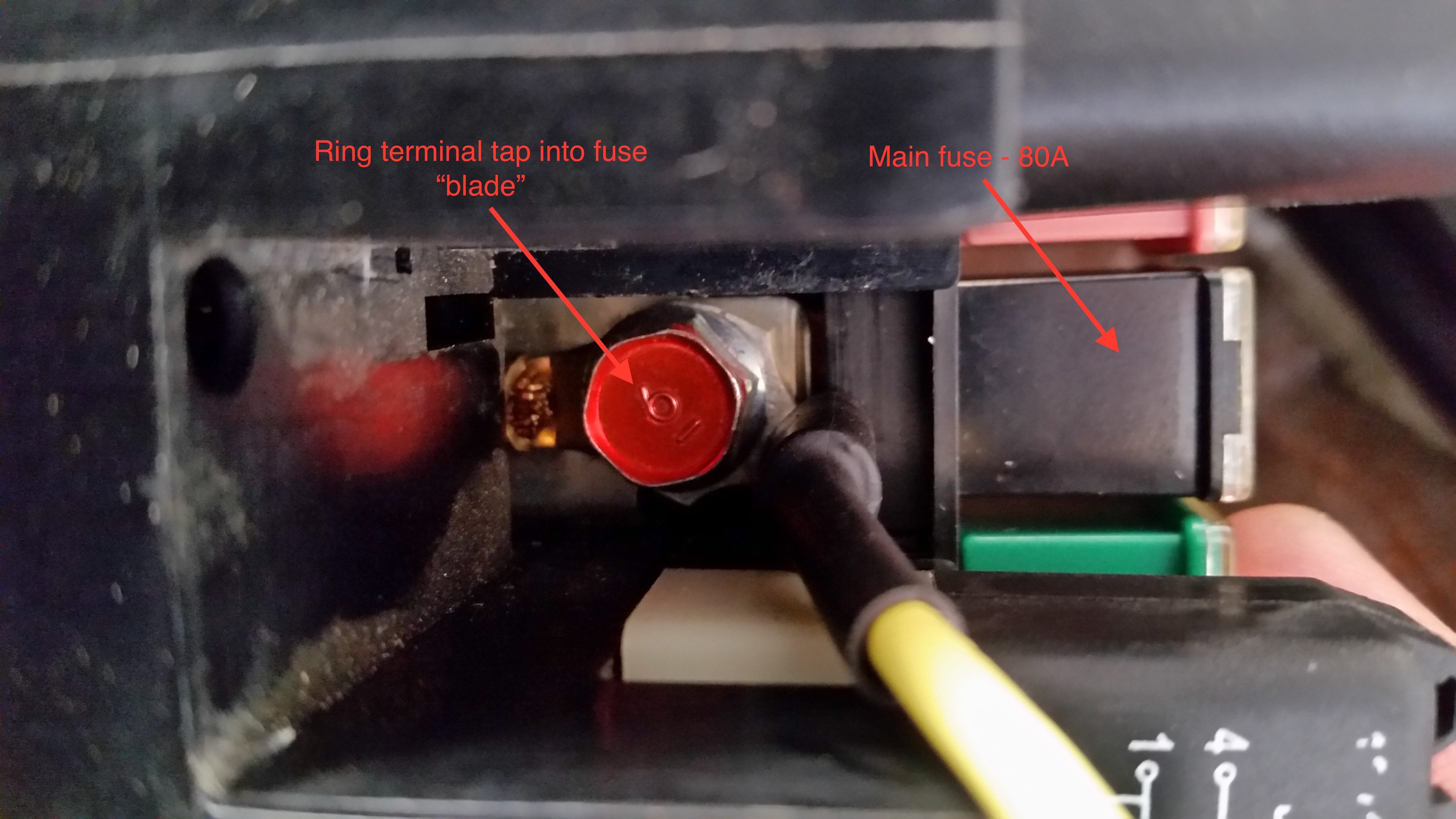
This isn�t my picture, but this is the main engine fuse
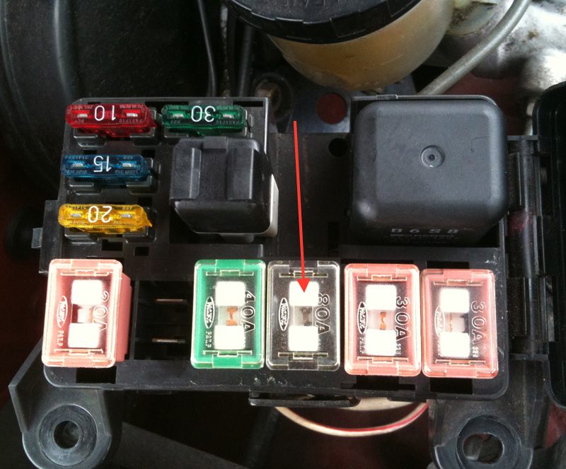
You can tap into this by using the existing bolt that holds each side of the fuel blades in. Use a ring terminal to tap into it or tee the two wires together and crimp on a new ring terminal:
There are 5 pink wires which all need switched 12v power (2 feed each bank of the engine for the coils and injectors. 1 is for the MAF, 2 are for the PCM). Some guides will mention just putting these all together and feeding it into a power source. If it requires switched power you should try to do that. Not saying it won�t work, but if OEM wants switched power, then there might be a good reason it�s done that way. Maybe so it won�t drain the battery while the car is off.
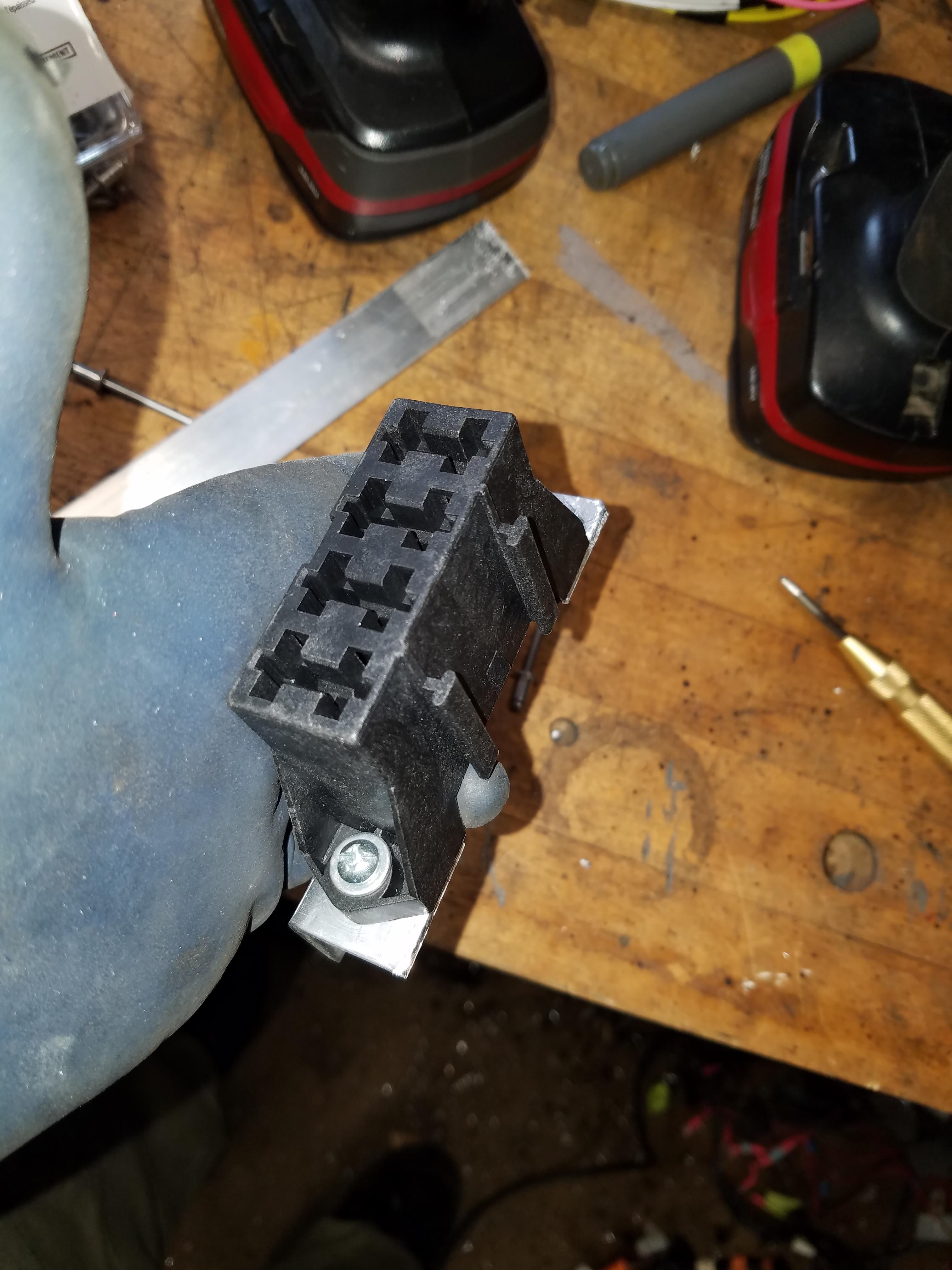
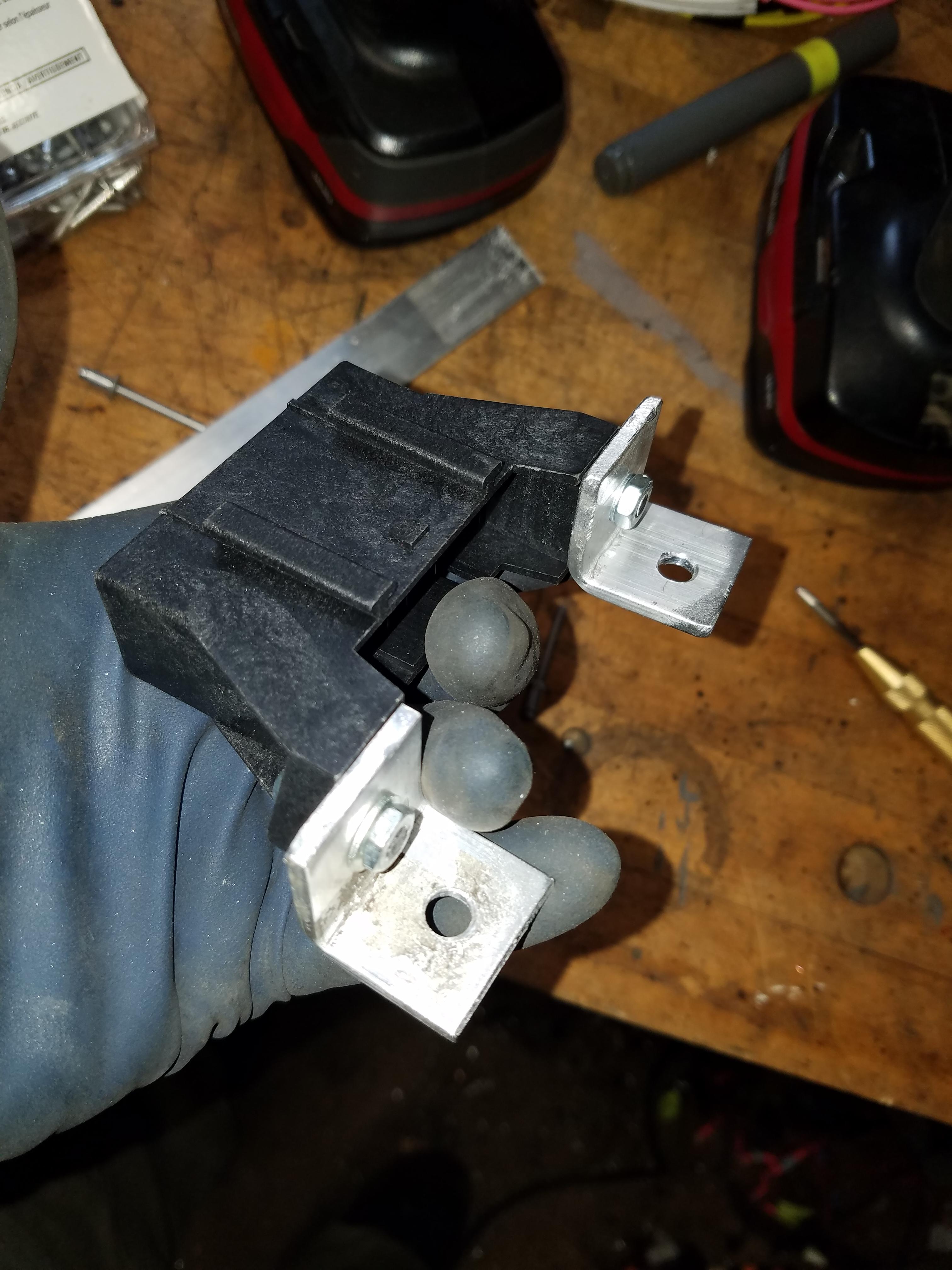
I purchased a small fuse panel that worked nicely
On the 99 Miata, at the ignition switch is a thick black/red wire, maybe 12 gauge, that provides switched power. I cut this wire and reconnected with a heat shrink crimp connector and ran a 10 gauge red wire from it. It went out through the firewall using a small, unused grommet/hole above the steering shaft. I will be also be using the grommet for the wires from the PCM going into the cabin.
Route the 10 gauge red wire over to the main fuse box. This wire will feed 3 fuses for the PCM and both sides of the engine (injectors and coils). Connect your pink wires up to your custom fuse block.
Once you�ve got your PCM location established (see an earlier post of mine to see what I did) and you have a working LS harness, my approach was to connect the harness to the PCM and bolt in both red and blue side connections, so it doesn�t pull out and damage the pins as you are tugging on the harness during install. It might be a good idea to make sure your battery is disconnected at this point, so your not sending power through the car or wiring by accident.
Lay the harness out on the engine and start making connections. For the most part this should be easy and satisfying - the positive click of a sensor connector going into place. This will start to give you an idea where the bulk of the harness will route. If you aren�t happy with it, you can con�t to pull it apart, extend or shorten wires, etc. to your preference.
I stripped off all electrical tape and plastic wire loom and used loose zip ties to keep things from getting out of control. Keep them loose so you can pull new wires through for later as you route things across the engine into the cabin.
First step was to make a good ground to the chassis by using an available bolt hole on the back of the driver�s side head. Connect the multiple black wire ground connections on the harness to this location with a ring terminal. Then add another 6-8 gauge connection from this bolt to the firewall or frame rail using the Miata locations.
On my car the 10 gauge (?) Black/Red cable that comes out near the Miata main fuse block, connects to the starter. The LS1 cable coming from the starter on my car was light purple, so I just connected those two securely with a crimp connector and weather seal.
Sidenote - For routing various things I�m using the corner of the engine bay on the passenger side, where you cut out the gussets early in your build, and where the tunnel, the firewall and engine bay frame rails meet. I have my fuel line, brake line and wires for the trans, o2 sensors, CKP (crank) sensor and starter connections going down here.
Power connections:
There are two orange wires in the LS1 harness that come out of the PCM, and then combine into one wire. This orange wire needs to be hot all the time so the PCM can retain its memory. I ran a wire with a 15A fuse through my own fuse block to the thick black wire from the battery. The black battery wire connects to the main fuse box where it bolts up with a ring terminal.
This isn�t my picture, but this is the main engine fuse
You can tap into this by using the existing bolt that holds each side of the fuel blades in. Use a ring terminal to tap into it or tee the two wires together and crimp on a new ring terminal:
There are 5 pink wires which all need switched 12v power (2 feed each bank of the engine for the coils and injectors. 1 is for the MAF, 2 are for the PCM). Some guides will mention just putting these all together and feeding it into a power source. If it requires switched power you should try to do that. Not saying it won�t work, but if OEM wants switched power, then there might be a good reason it�s done that way. Maybe so it won�t drain the battery while the car is off.
I purchased a small fuse panel that worked nicely
On the 99 Miata, at the ignition switch is a thick black/red wire, maybe 12 gauge, that provides switched power. I cut this wire and reconnected with a heat shrink crimp connector and ran a 10 gauge red wire from it. It went out through the firewall using a small, unused grommet/hole above the steering shaft. I will be also be using the grommet for the wires from the PCM going into the cabin.
Route the 10 gauge red wire over to the main fuse box. This wire will feed 3 fuses for the PCM and both sides of the engine (injectors and coils). Connect your pink wires up to your custom fuse block.


