When you click on links to various merchants on this site and make a purchase, this can result in this site earning a commission. Affiliate programs and affiliations include, but are not limited to, the eBay Partner Network.
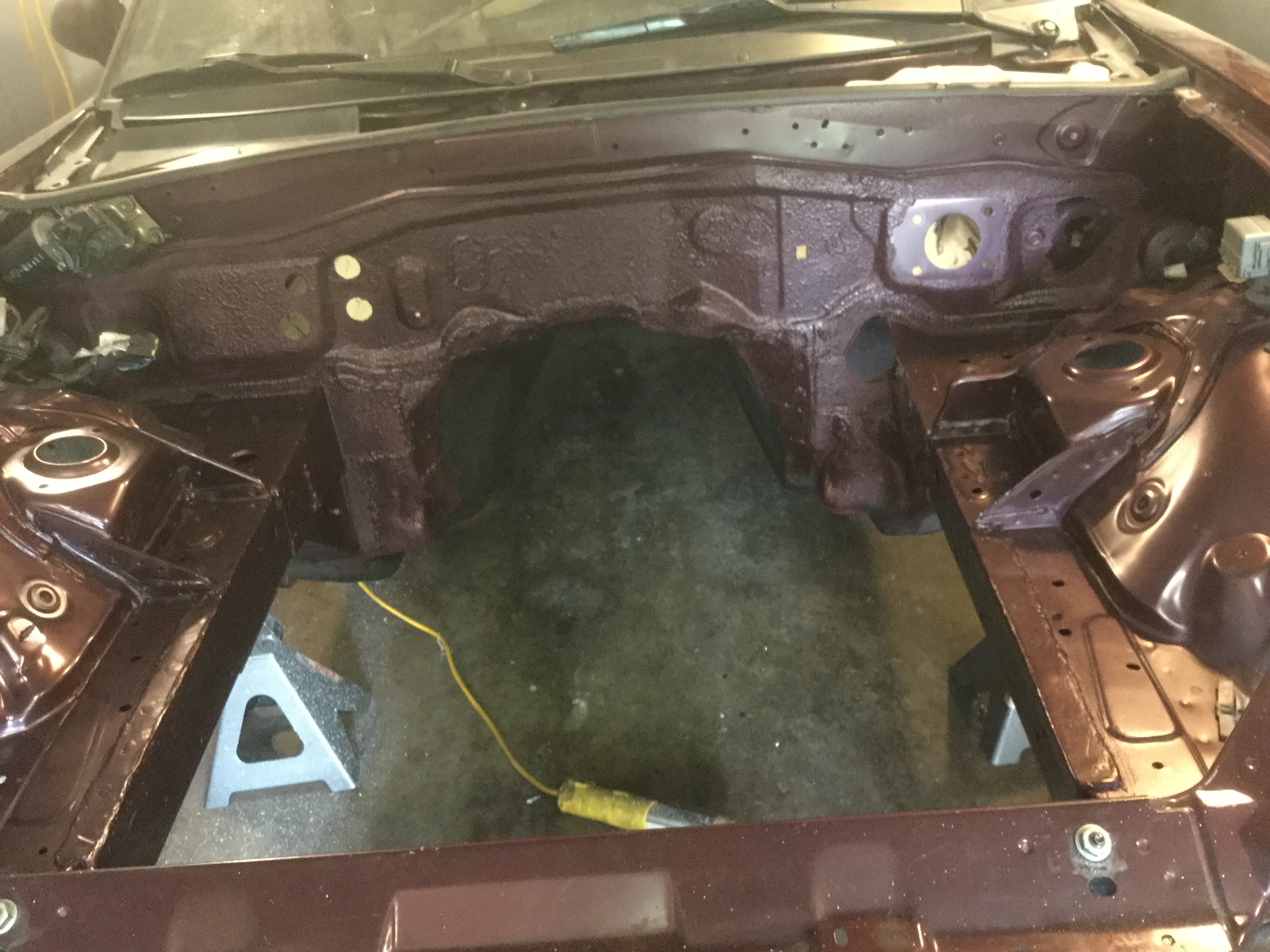
The engine bay is all done and ready for stuff to get installed.
I did put Lizard Skin temperature control spray on the engine side of the firewall then waited for it to dry for a couple of days before painting the engine bay with some factory color match paint.
Worked out great and the end product looks real good. You can tell where the Lizard Skin was sprayed because it has a rough texture.
In this picture you can also see the frame rails with the stiffener gussets that were welded into the upper inside corners.
They looked a bit rough before paint but cleaned up pretty good. It is amazing how much cosmetic roughness paint will hide.
The Lizard skin noise control product was grey but for some reason the temperature control was white. My guess is it probably comes in other colors but for some reason I did not notice and bought white when placing the order. On the under side of the car I went ahead and sprayed some flat black paint over it but since the passenger compartment will get covered by carpeting I left it white.
After a little checking, the temperature control product also does some sound deadening but not as much as the dedicated sound deadening product. In hind sight I would have gotten 1 gallon of each and used the sound control inside the passenger compartment and the temperature control under the car and on the engine side of the firewall. If I ever do another car, it will be one of the things I will know.
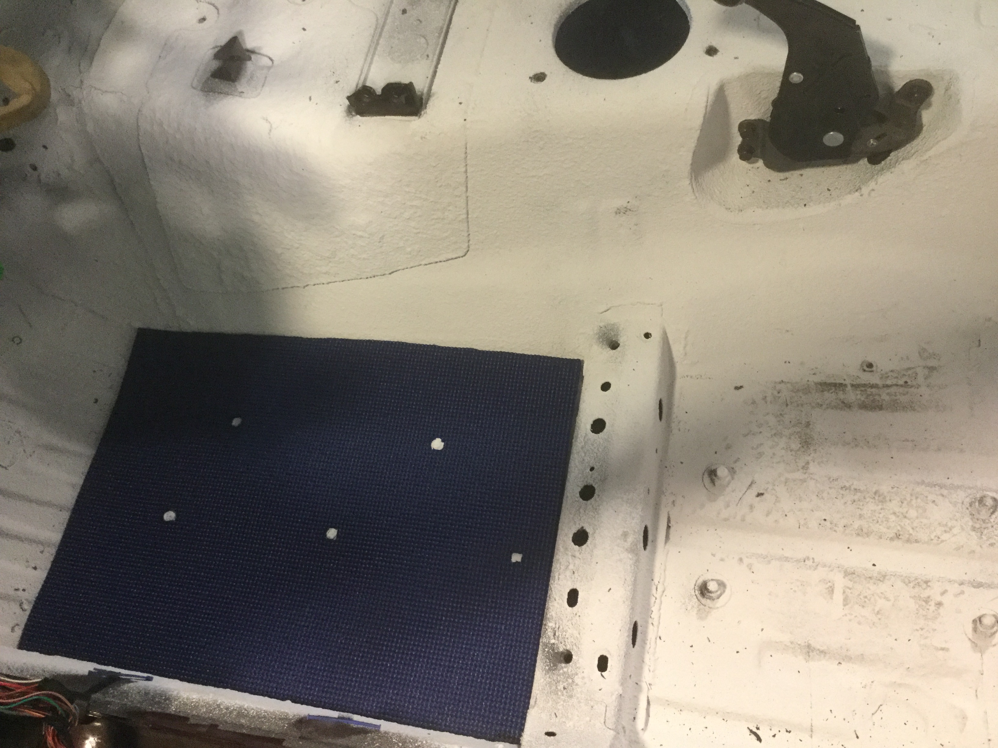
Back to the interior. The bolts that stick thru the floor that hold the subframe stiffeners to the floor feel like they will be an annoyance to my feet so I decided to put something down. For matting I went to Wal-Mart and got one of the rubberized Yoga mats. The matting got trimmed where the bolts are located (white spots) and after two layers the matting sits flush with the bolt. Should take care of any annoyance to my feet.
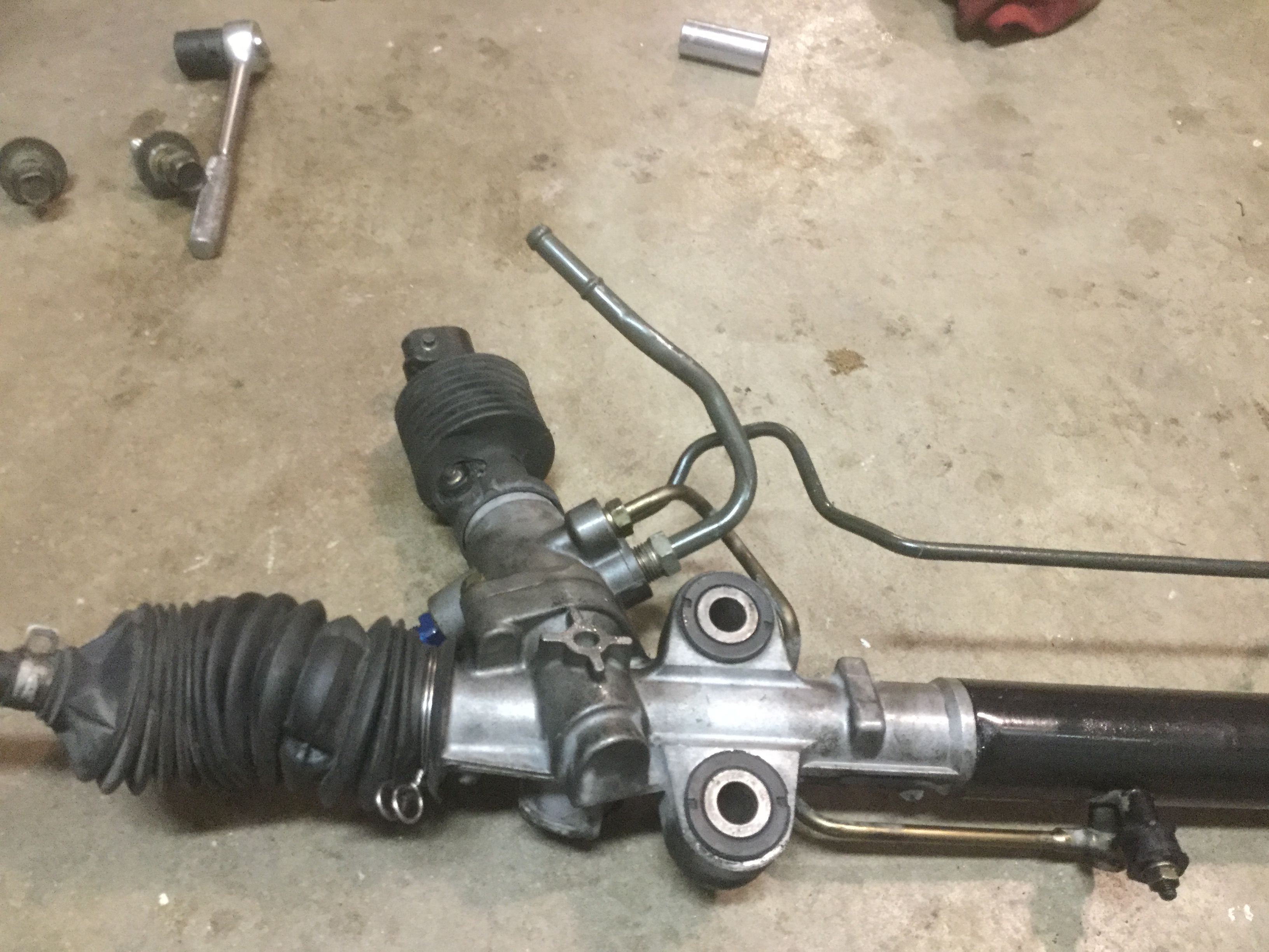
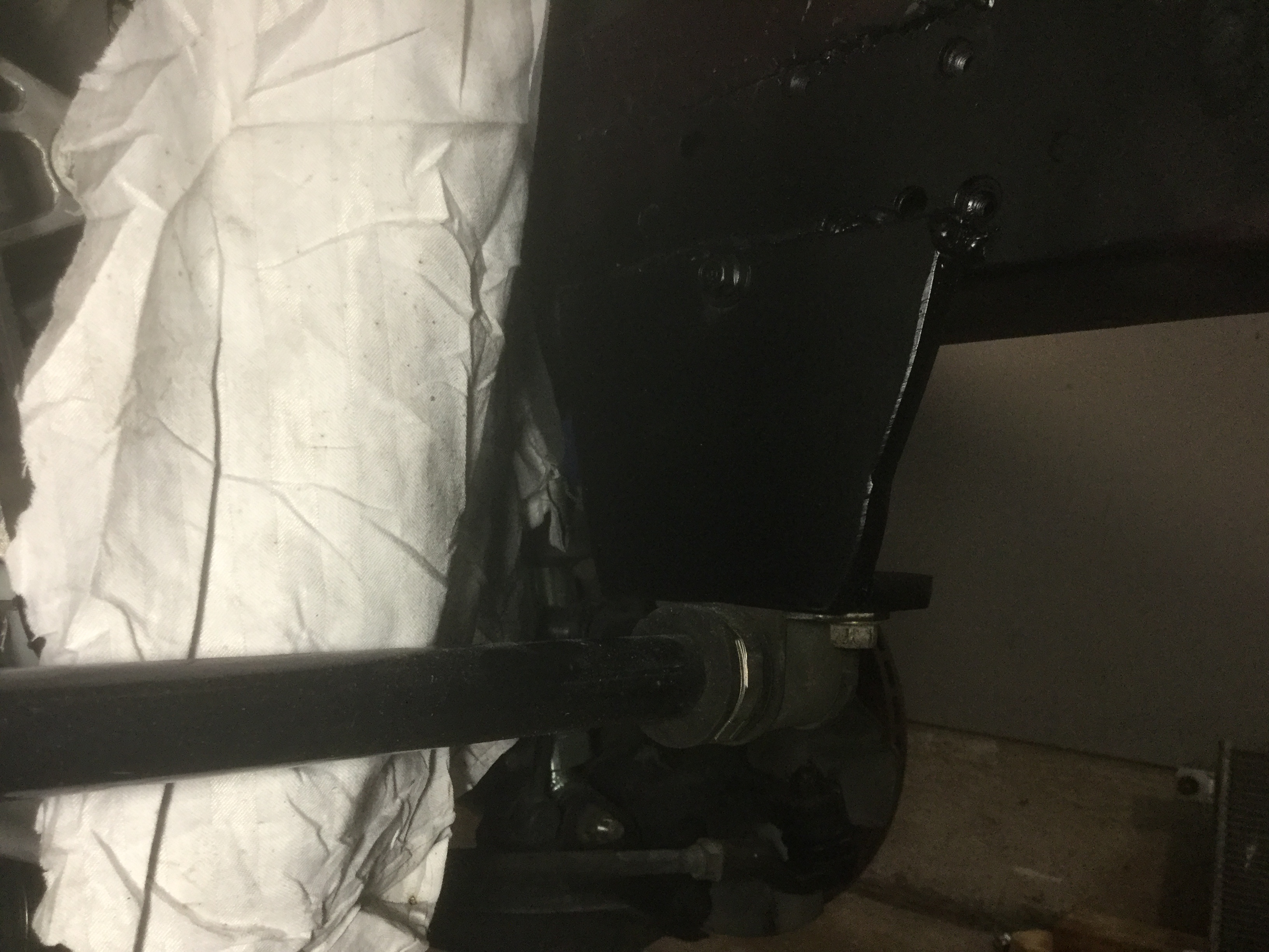
Getting the tubing for the power steering rack to fit around the oil pan took a bit of bending. All the lines were left in place but loosened slightly in case any of the ends needed to rotate. On the right side the tube hit the oil pan in two places but it was real simple to take a ratchet handle and put it between the tubing and the pan and pry it to move the tubing just enough to gain the necessary clearance. The same tube on the driver's side also had to be bent a bit to clear.
The low pressure return tube was a bit more hassle. The original bend made the tube try to go right where the new subframe sits so it took a bit more bending to get it into a reasonable location. I just straightened it out a bit until it would go on and off at the same time as the rack assembly. The Flyin Miata kit has some high pressure rubber tubing and some clamps to allow it to be routed to the return connection on the CTS-V power steering pump. I will probably do a clamp on the side frame rail to keep the tubing from getting too close to the header pipe.
The picture shows the final shape of the return hard tubing.
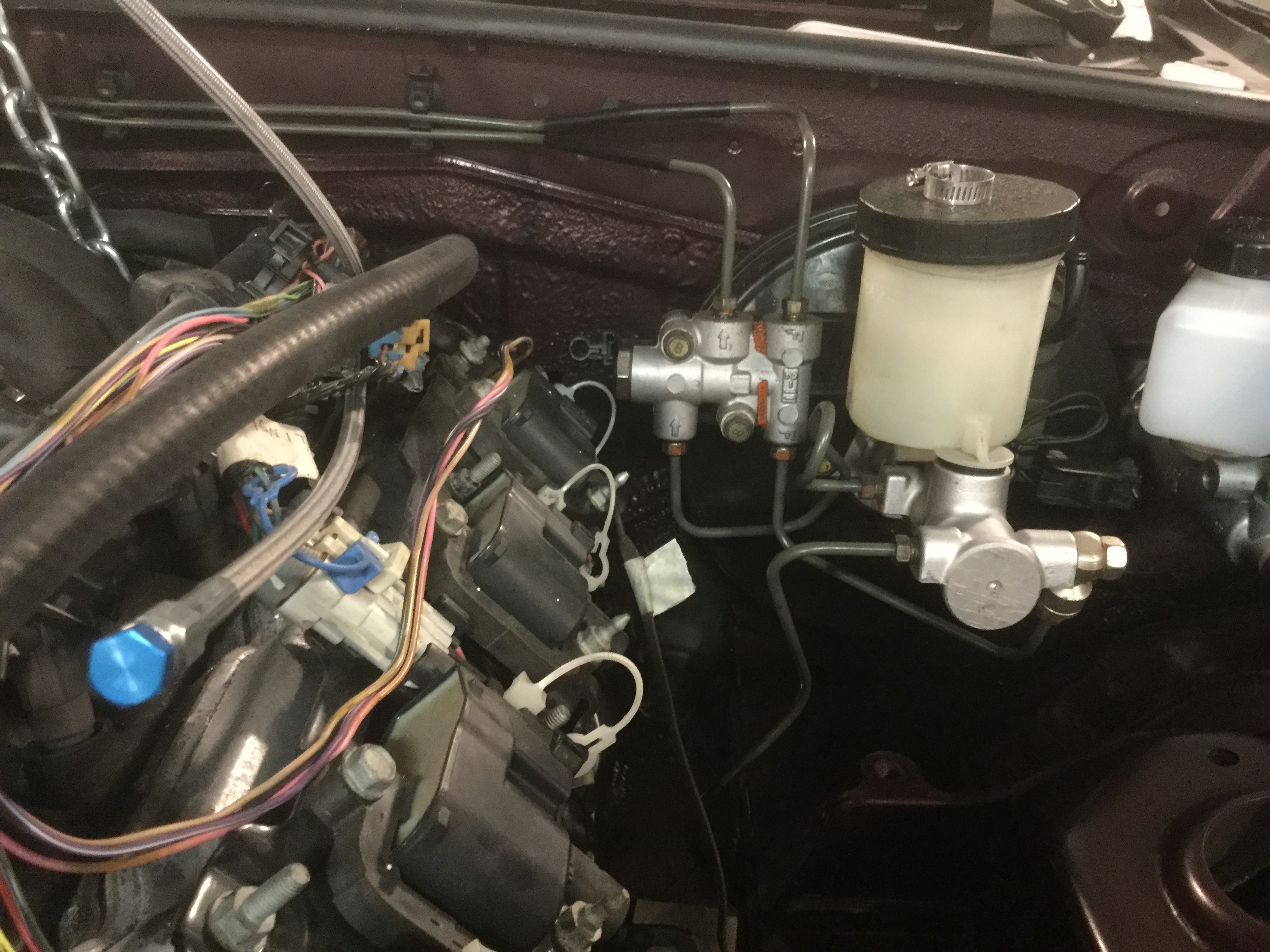
The Flyin Miata instructions are pretty slim when talking about the brake lines. They simply say to bend the brake lines to clear the enlarged transmission tunnel.
I did not take a picture of the brake lines before bending but they were definitely not going to work. When you get to that point, install them and then scratch your head for a minute. There might be other ways to get the job done but I found that simply using my hands to carefully re-bend the tubes to go towards the passenger side frame rail worked out pretty well.
Once they were roughly in the location I felt would be usable, I did a trial fit of the engine and found out I had to move them some more. If you look hard at my picture, hopefully you can get it bent correctly the first time.
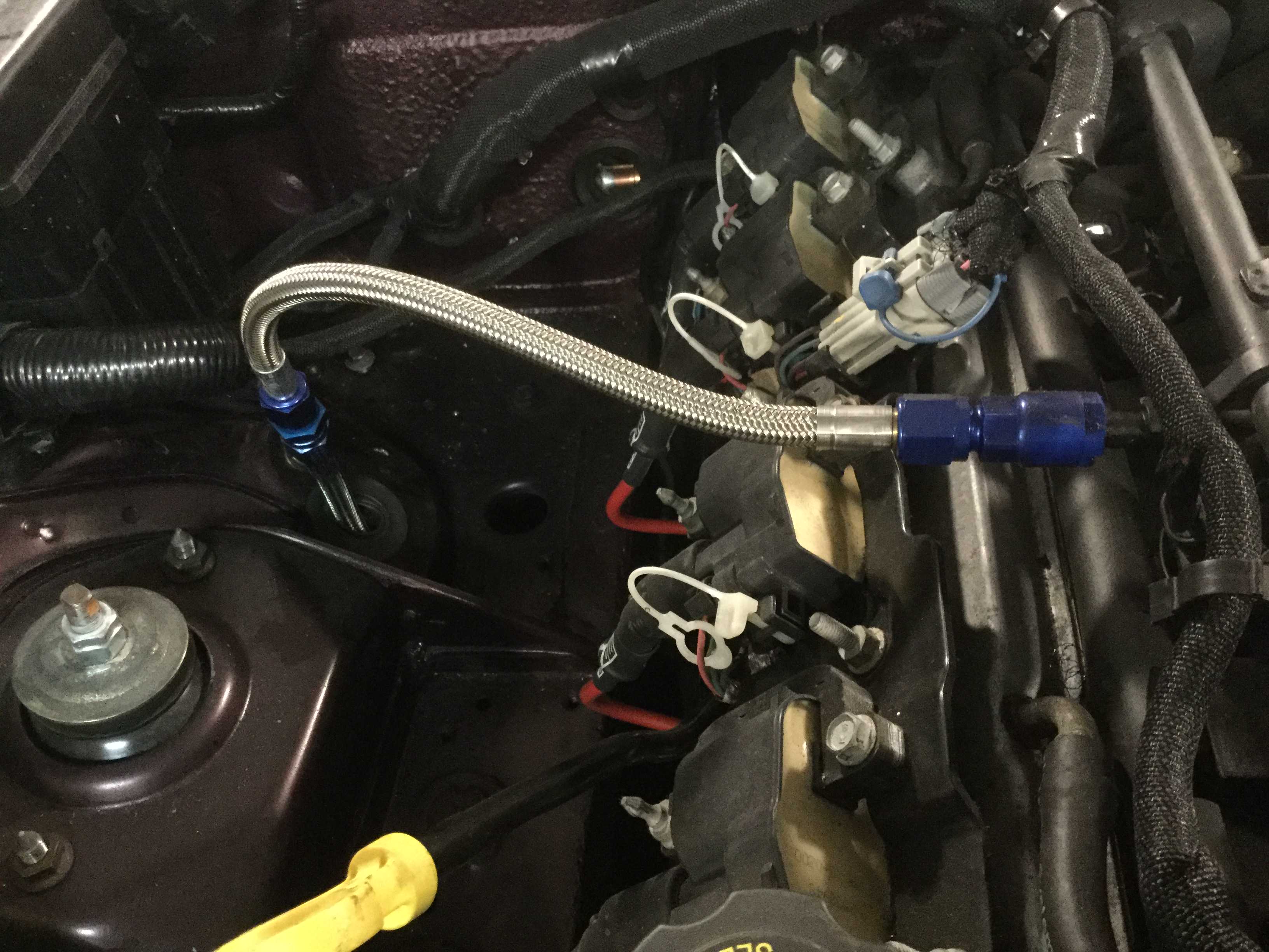
Once I was happy with the location I put a couple of clamps to keep them close to the firewall and away from the headers. At the same time I clamped the fuel line to the frame rail to keep it as far away from the header heat as possible. I also wrapped the braided line in some reflective aluminum wrap (not shown in the picture) to hopefully reflect the heat away from the fuel line. It doesn't really look like it in the picture but everything is tight against the frame rail.
Edit;
After doing a test fit I do not like how close to the headers the fuel line is running so I re-routed the line as detailed in one of the later posts. Doing so required purchasing a short piece of prefabricated braided fuel line and an adaptor.
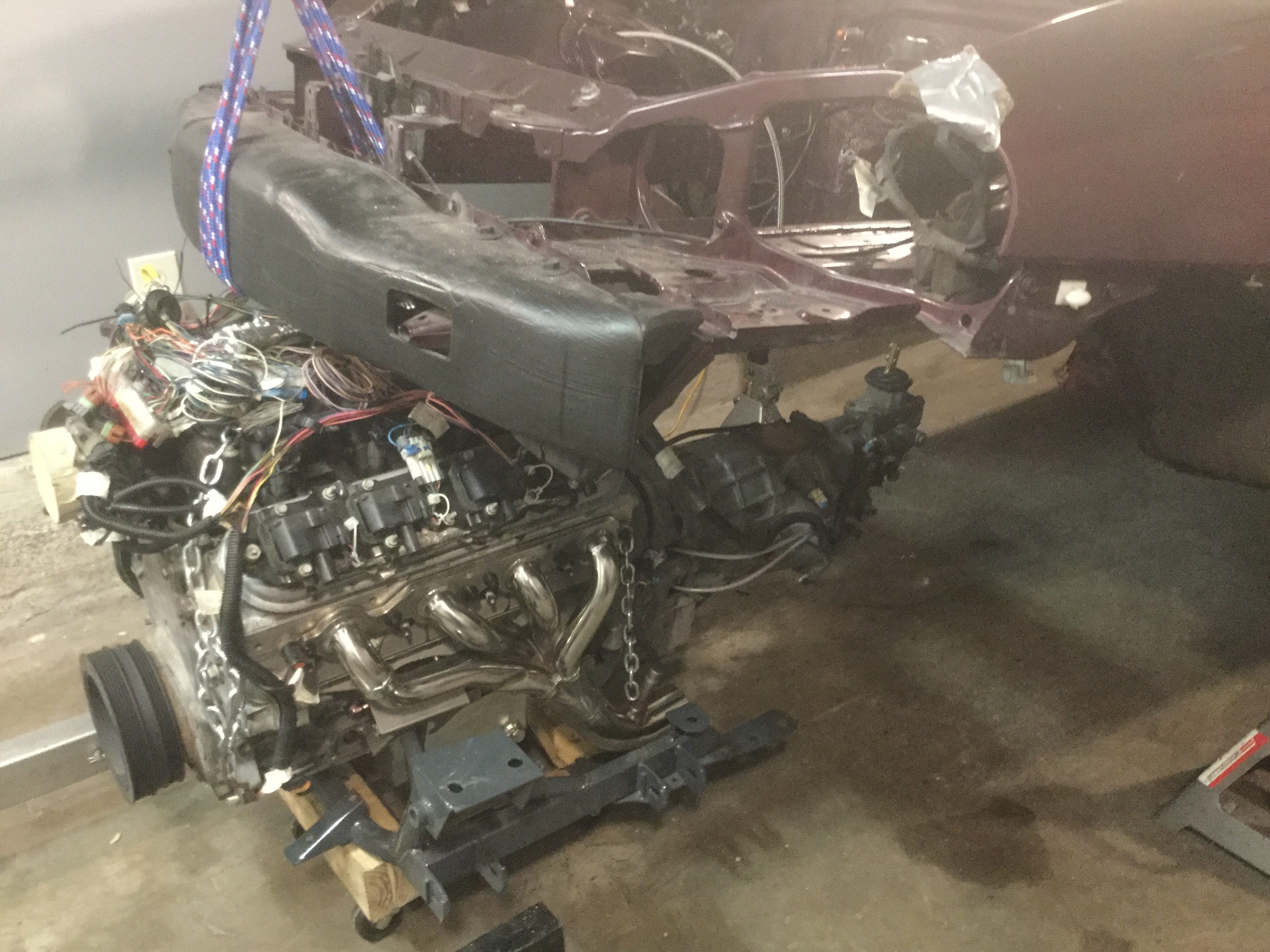
Up next is what I am hoping is the final install of the motor and transmission into the Miata.
Feels like a really special thing and I was tempted to have a beer to celebrate.
Will probably have a couple of issues to work thru.
One is how to remove the chain and bolts that are tight between the engine and firewall.
Guys with a lift do not have these sort of problems but us bootstrap types have it to figure out.
My first thought is that I will use blocks to hold the engine in it's present location and raise the body up enough to get to the bolts.
Also, still have a number to things to decide.
The wiring harness is first.
Having the extra long Painless Wiring Harness sure seems like a nice way to go but as I look it sure seems like the LS1 harness will work out decently well.
The Painless harness would allow the ECU to mount behind the passenger seat and away from the engine compartment.
That will clean up under the hood quite a bit but on the other hand it seems like the Miata main fuse box will have enough connections available to work with the LS1 harness.
The Painless harness has it's own fuse box and is new and just what is needed rather than being 17 years old and needing to be modified to work correctly.
one thing i wish i had done is enlarge the shifter opening inside the cabin so that the shifter could be removed. I ended up making the cuts with the transmission installed which made it 10x harder.
maybe i missed it in your writeup, but how are you getting the wiring though the firewall?
On the wiring thru the firewall, I haven't decided on a location yet. Still trying to decide which wiring harness to utilize. Honestly, the wiring has been the part I am dreading.
Since I have to change the location of the heater hose connections, there will be two holes available for wiring or I might put another hole in the corner of the passenger side of the firewall.
Thanks for the heads up on the shifter opening. I can mark the enlargement then actually make the cut when I lower the engine to remove the rigging chain on the back side of the engine.
Working on the wiring.
It doesn't look like much but I have spent about 8 hours getting the wiring to this point.
Trying to be careful and methodical. Ended up lowering the motor to allow decent access to the wiring locations.
Much easier to run and wrap the various wiring connections cause it is real tight around the firewall area with the engine in place.
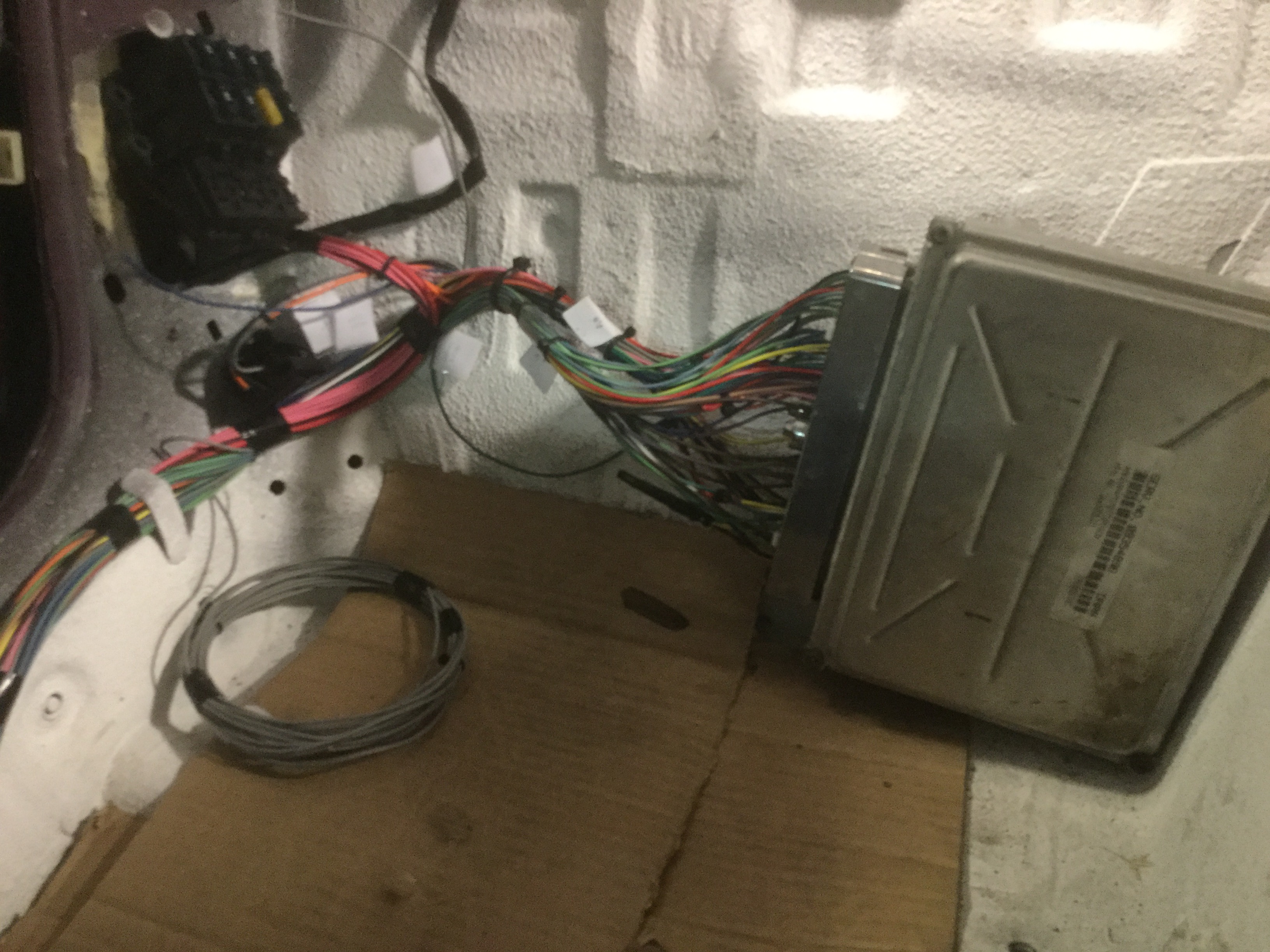
With the extended length Painless wiring harness laid out about where it will go inside the passenger compartment it looks like mounting the ECU behind the passenger seat will work out really well. The harness instructions say to mount the fuse box within 18" of the ECU and they wire them so that has to happen. There are a couple of options for the fuse box and hopefully what I have in mind will be nice and clean. The passenger seat and one plastic interior panel need to be installed to verify what locations will work.
If the parcel shelf is the area where the convertible top lays on when down the answer is no because I have a soft top.
If you are talking about the area underneath the shelf that has a removable steel cover, the available area is too small for the ECU
There is, however, enough wire in the harness to fit behind the seat but not enough to go all the way into the trunk.
Sitting behind the passenger seat against the rear panel looks like the best placement as long as the seat movement will allow for it to go there.
From the second picture you can see there is a cutout in the body panel to allow access to a door closure wire. The cutout looks to be a good size for the fuse box but will require cutting the plastic interior piece that covers that opening.
Edit:
After installing the interior I finished up the cosmetic portion of locating the wiring harness fuse module and ECU.
The opening in the chassis just behind the passenger door is hidden by a plastic interior piece and worked very well to contain the fuse module.
I marked and trimmed the plastic piece and test fit it several times before the fit was just right.
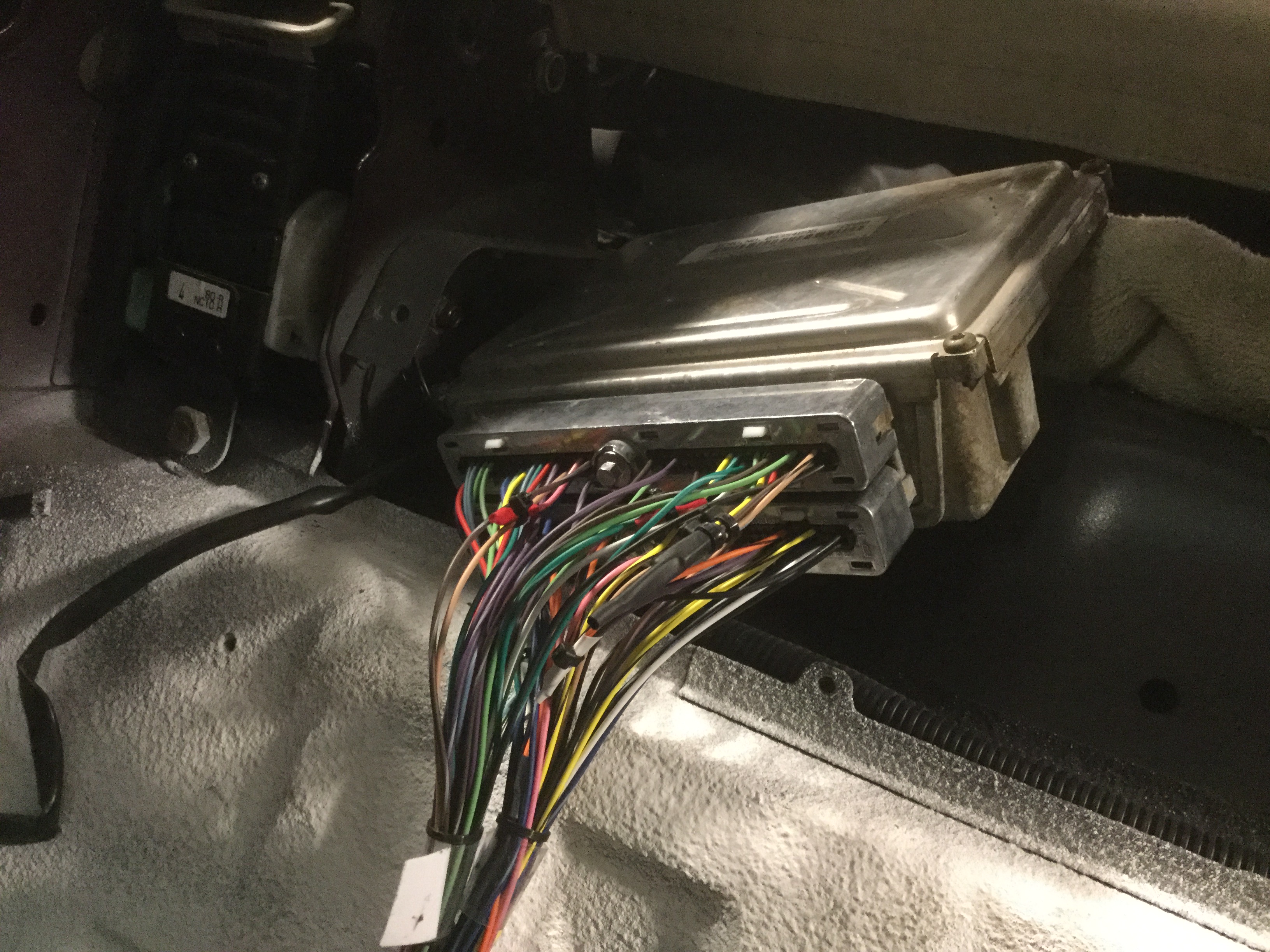
The wiring between the ECU and fuse module is pretty short so the ECU has to mount next to the fuses, which tied down the ECU final location to the location it is installed at.
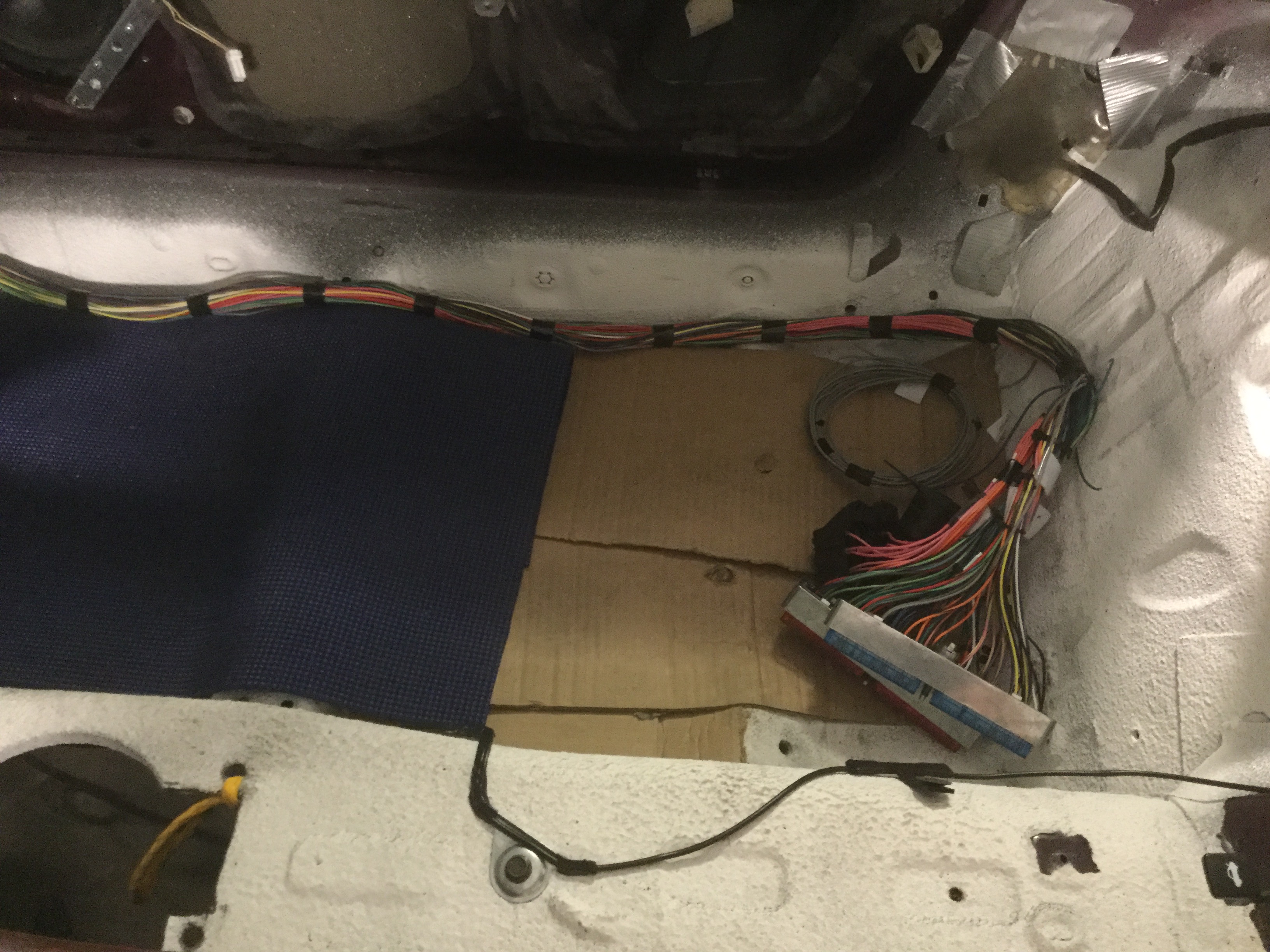
After making a couple of aluminum brackets and slicing two openings in the carpet behind the passenger seat it all got installed.
The bulky bundles of wires makes the carpeting bulge a bit but all in all it worked out pretty well.
Keep in mind that it will all be hidden behind the passenger seat back after the seat gets installed.
The depth of the ECU is about 3" which cuts into the amount of rear movement of the passenger seat.
Not a problem for me but could be an issue for a passenger taller than 6'.
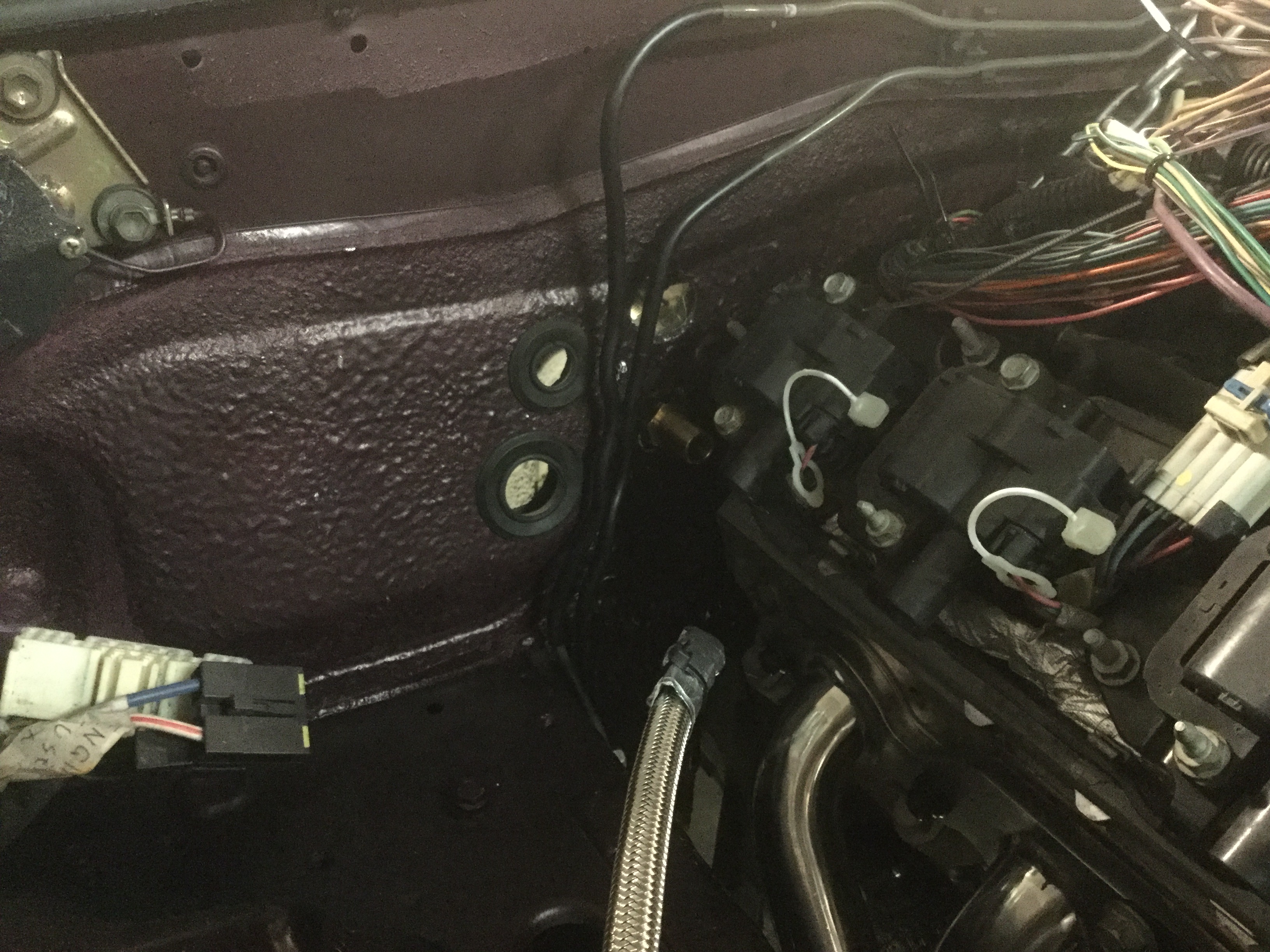
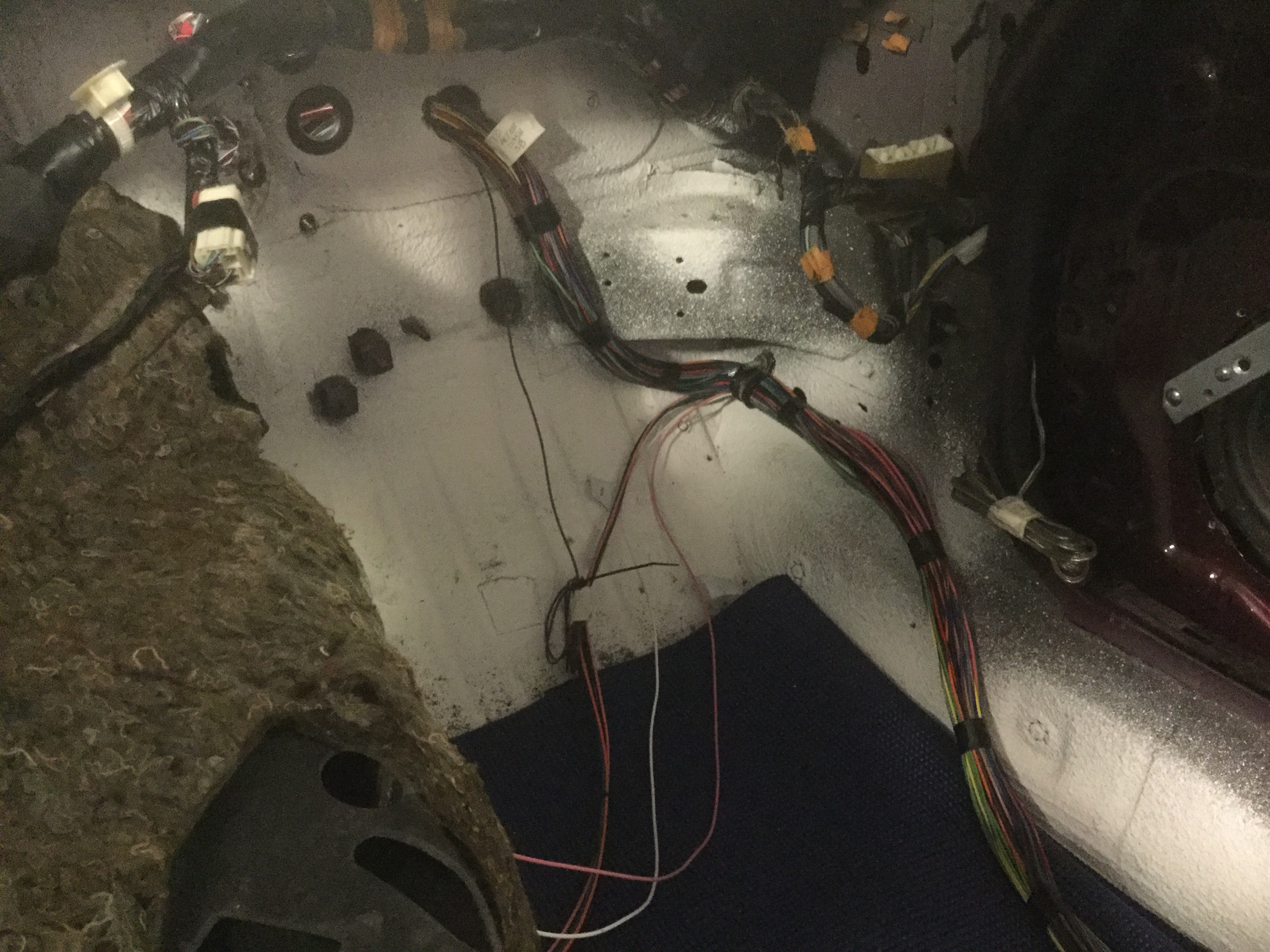
This picture shows the location of the hole in the firewall and the routing of the wire bundle.
As you can see, if I need a few more inches for some reason I could get it by running the wire bundle straight along the floor rather than snaking it around the edge. All in all I think I will be real happy with how it will clean up the engine compartment.
Making electrical progress on the car.
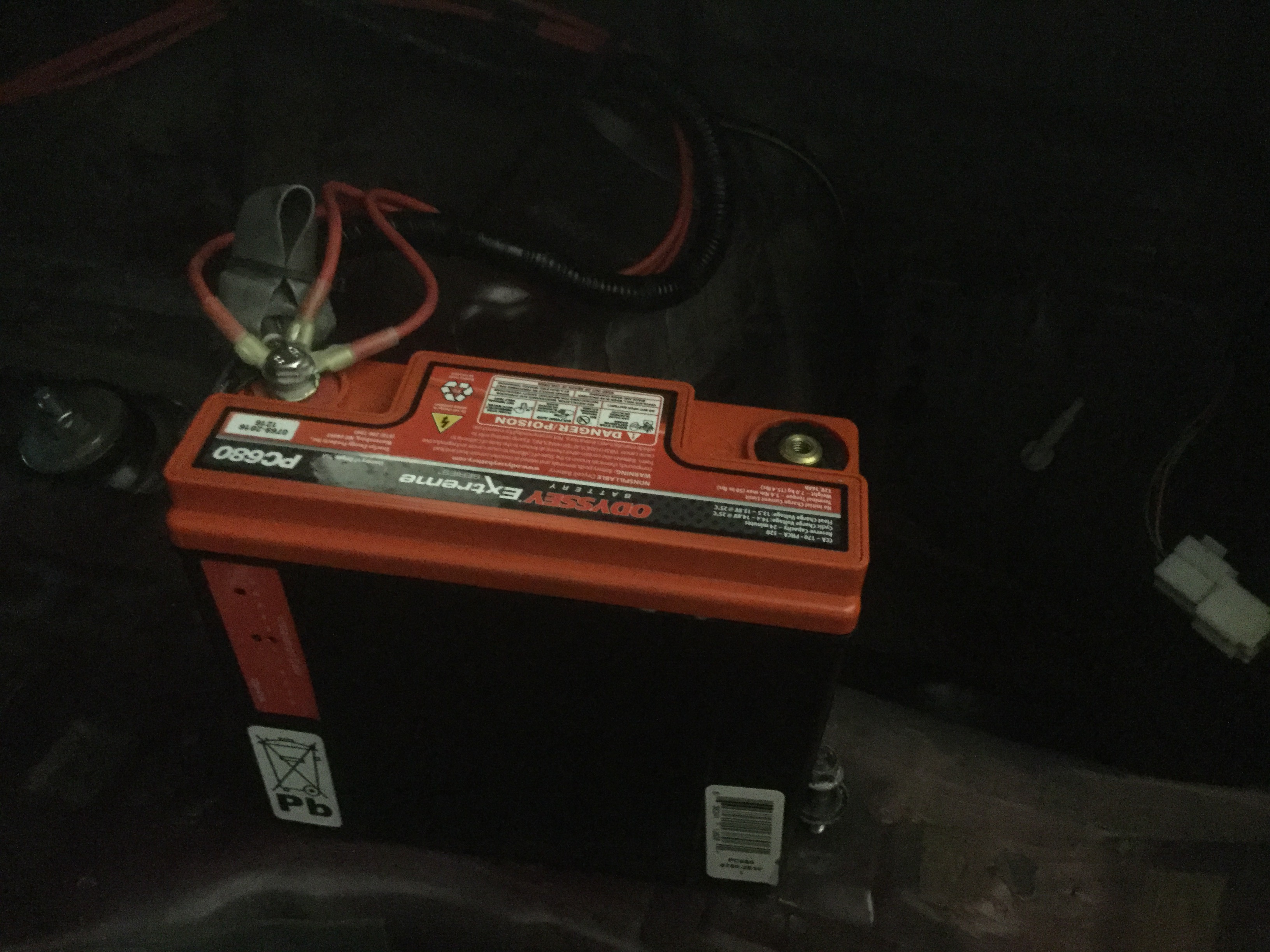
Bought an Odyssey battery.
It is rated for a C7 Corvette but about the size of a motorcycle battery and can be turned any direction without worrying about leakage. The plus and minus connections are just 6mm bolts (10mm heads).
Connecting it works out real well with the factory Miata cables. Just trim off the circular post clamp portion and it leaves you a flat piece of metal with the correct hole.
There are several secondary connections to the plus side of the battery. The main cable connection, two red wires that go to the Painless Wiring fuse box and one red wire that goes to my home made fuel pump circuit. After taking this picture I combined the three red accessory hot wires into a single end so there are only two connections to the plus side of the battery. The factory Miata rubber cover was big enough that it could be slid over both the wires so the completed piece looks clean and neat.
Edit after the fact;
The multitude of wires connecting individually to the positive bolt just looks home made and trashy so I cut the ends on all three and combined them all together into one bundle with a single end connector and a nice piece of shrink wrap over the bundle to make it look nice and professional.
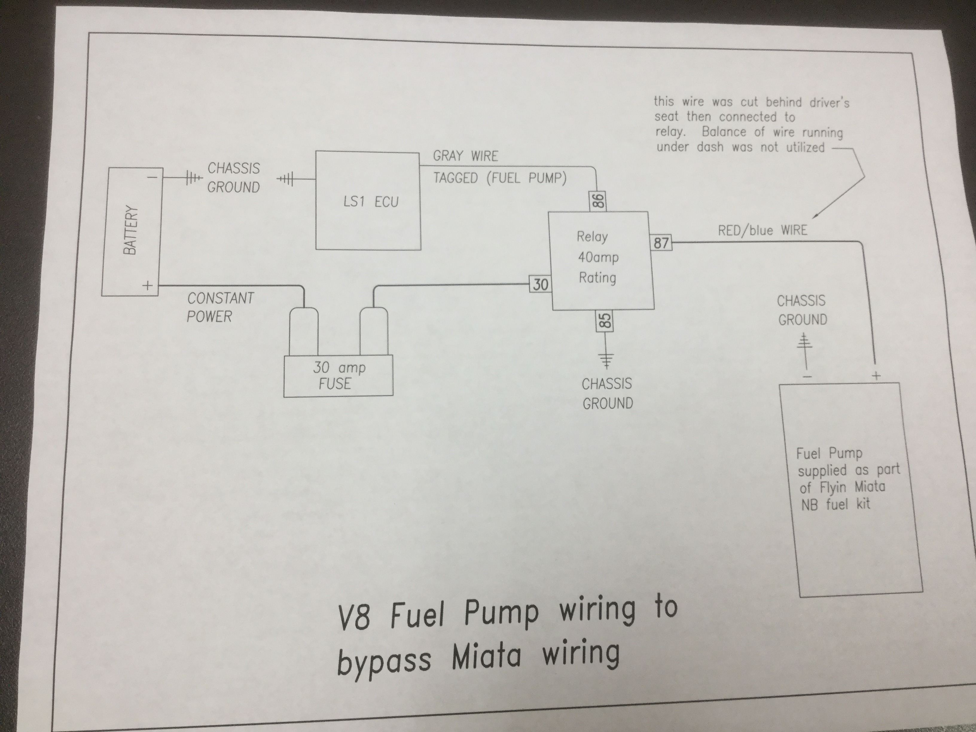
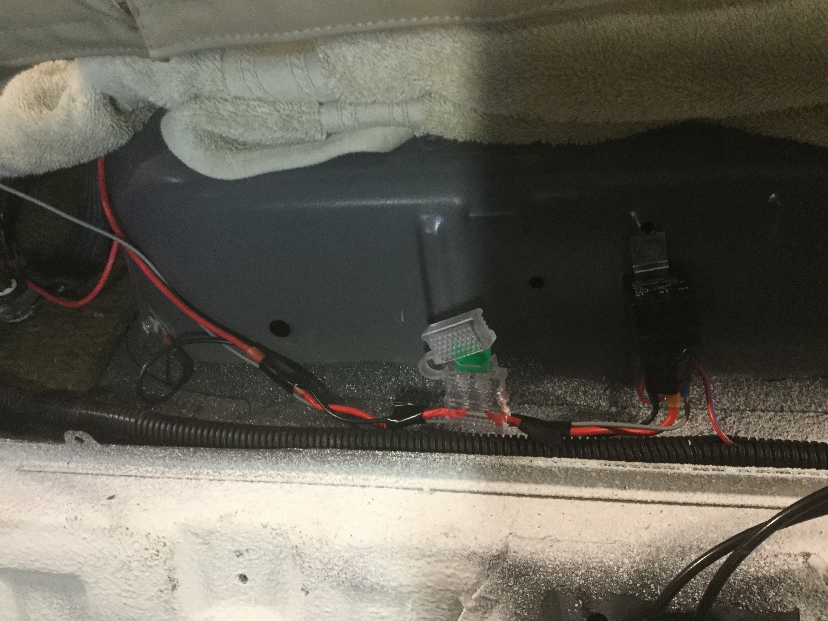
Here is a picture of the wired connection that I scabbed together for the fuel pump power. It seems to work outstandingly well. It has an inline 30 amp fuse, a 40 amp relay and then connects to about a foot of the Miata fuel pump wire. For the light gauge portion of the relay circuit I connected the gray wire from the ECU to one side of the relay and then ran a ground wire to the other side. You can see where I grounded the wire to the fuel tank cover on the far left side of the picture. When I turn the ignition key to the first position the pump is noisy for about one second but then is nice and quiet. My hope is that it stays nice and quiet while I am driving. Also made a sketch to show a diagram of how the wiring was done.
Edit: After figuring out that the fuse location is not accessible once the steel cover piece and carpeting is installed I moved the fuse location to be as close to the battery as possible. It works out well as there is just a cosmetic covering in the trunk so access to the battery area is nice and simple.
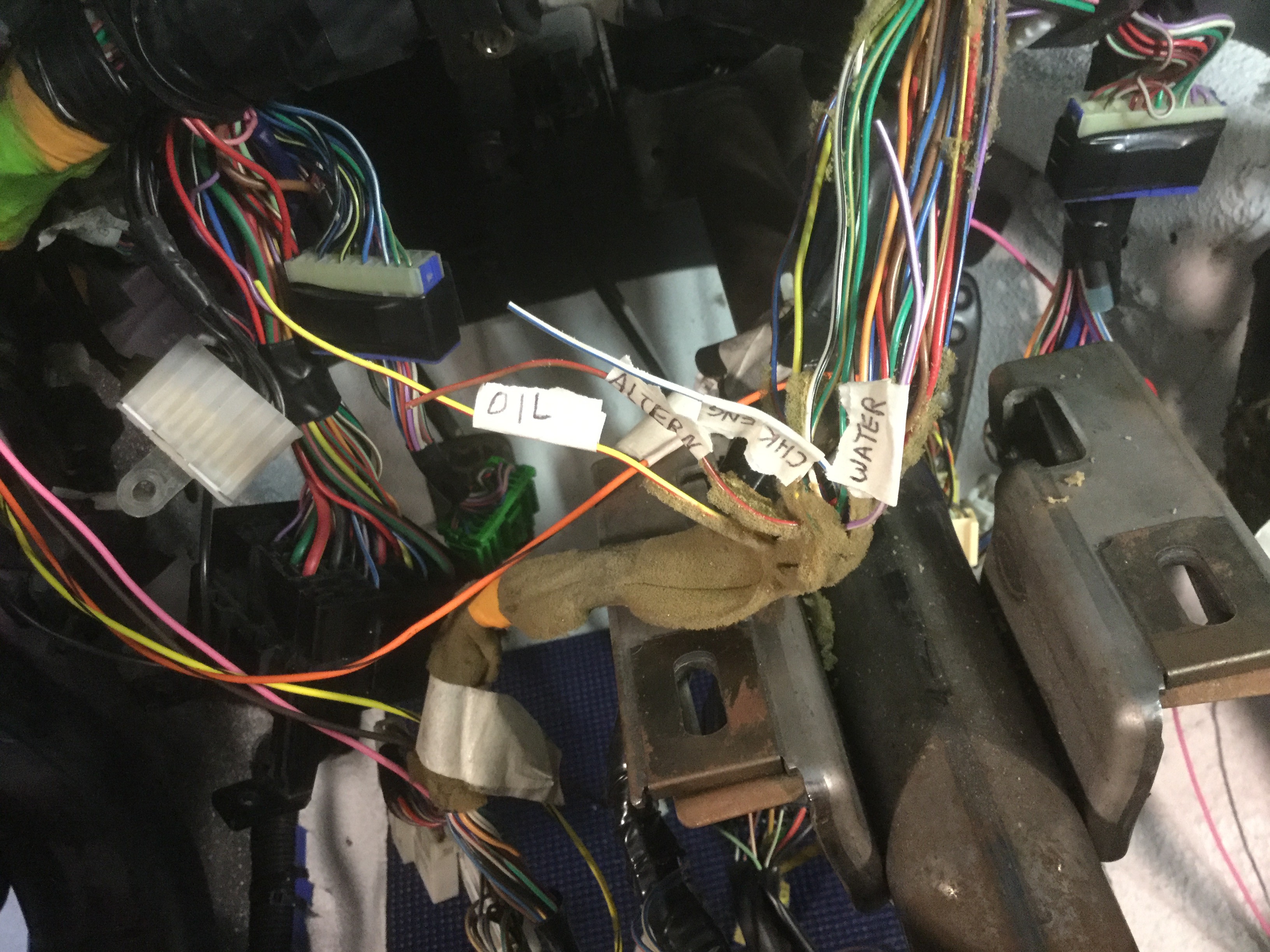
Next thing I have been working on is identifying the instrument cluster wires that will need to be spliced into. The Flyin Miata instructions appear to be accurate for my year.
The engine is just about ready for it's maiden start up. All the fluids are in and hopefully all the proper connections have been made. At some point in the next couple of days I will give it a test start before dropping the engine and front subframe out of the car one last time to finish up the wiring harness and fuel and brake line routing and covers.
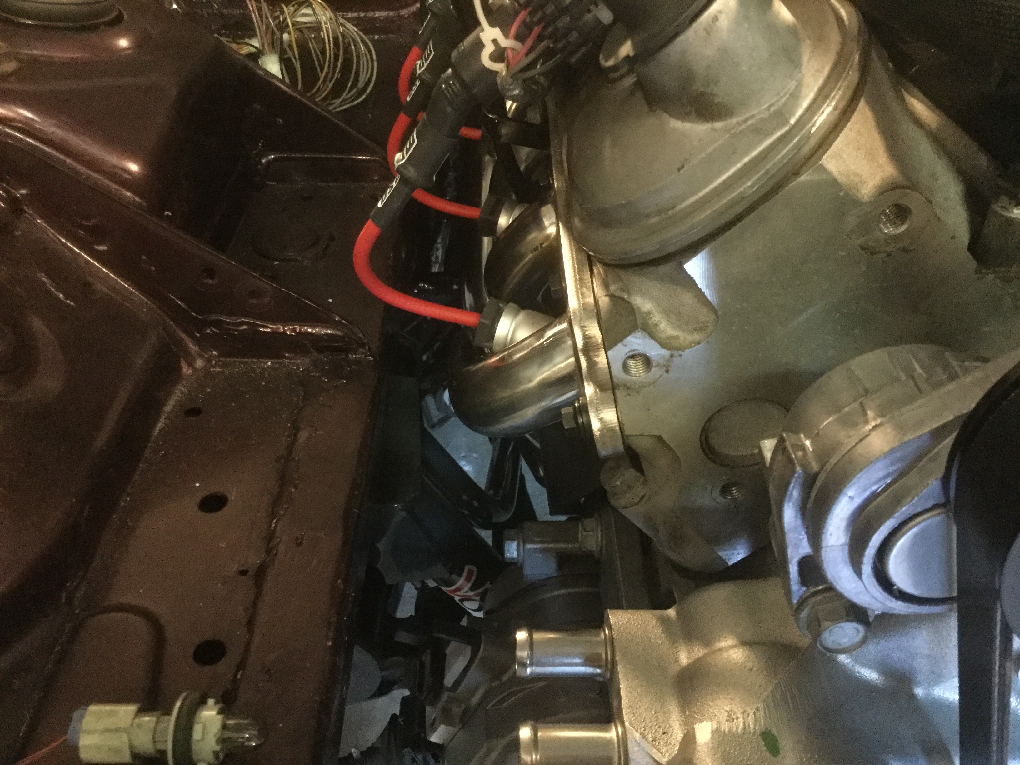
It is tough to tell from the pictures but I am real happy with the amount of space between the frame rails and the headers. The passenger side is tighter than the driver's side but both have enough space to work.
Driver's side
Not much visible progress to report but did do the first test start and it went smoothly.
My wife was standing by with a fire extinguisher in case the worst happened but no need.
The car started and ran smoothly. Since the cooling system is not in the car yet, the run was only for about a minute.
Checked the gauges and they seem to work. The engine has 50 lbs of oil pressure at cold idle and no smoke at cold startup or idle so it looks like I got a good motor. After killing the engine and letting it cool down for a few minutes while I looked everything over, I started it up again in first gear to make sure the transmission and differential work. Both seem quiet and worked, at least for the short test start.
The one gripe I do have is with the Flyin Miata electrical instructions. The descriptions for some of the hookups are simple. Hook up this ECU wire to this specific Miata wire. If the instructions get beyond that level of complexity they rely on verbal descriptions that are very confusing. A couple of simple pictures or sketches would keep a home swapper from lots of wasted time and hair pulling. The tachometer and speedometer instructions gave me real headaches. I am going to send them an e-mail with a couple of sketches that I feel would make the tie in connections much easier to understand.
Also, I purchased some Dynomat sheets to use in addition to the Lizard Skin product that was sprayed in place a few weeks ago. The noise insulation situation needs more than just spray insulation and the adhesive backed sheets should work well in areas where the spray insulation was not utilized. In particular, the area behind the seats where the fuel tank resides was not touched during the conversion process so it was not sprayed. Some of the Dynomat should help the road noise coming from that area.
Edit;
How ever much sound insulation you utilize, please go ahead and add some more.
A single layer of Dynomat was not enough. In hind sight I wish I had sprayed Lizard Skin into the trunk and the area underneath the soft top ledge.
Something I did not like was the routing of the fuel line that came with the Flyin Miata fuel kit. Looking at the video or the completed Flyin Miata car shows the fuel and brake lines running along the inside of the passenger side frame stiffener channel that runs the length of the underside of the car. Up near the front where the front subframe bolts to the chassis is a tight area and the hose is routed in this area, VERY close to the exhaust. I just do not like this hot area for fuel lines so I ran the line on the outside of the frame rail and up the inside of the fender well then drilled a hole between the inner fenderwell and the engine compartment.
This made the supplied braided fuel line too short so I purchased a 6AN coupling and 12" piece of braided line to get enough length. There appears to be plenty of clearance between the fuel line and the tire even at full lock but I will probably also install a plate cover to give additional protection to the fuel line.
Most of my time has been spent on simply making stuff neat and covered and as close to factory look as I can get. In order to stay well organized I am trying to work from the back of the car forwards to finish up one area before moving on to the next. Some ordered parts are still rolling in and I do still have to order a bunch of stuff before finishing up. Early on I ordered a huge wad of parts and found out that too much stuff lays around for weeks and weeks waiting to be utilized so now I am ordering stuff about a week before I feel it will actually be needed. With a one car garage it is real important to keep everything organized and only have the things you need. Before ordering the radiator and intake and exhaust, my plan is to get the interior finished up. Based on that timeline, my guess is that it will be late July before ordering the big stuff to finish the car and the car should get done around late August or early September.
Now that I have gotten past the areas that were my big worries before starting the project (dash removal, electrical), my one worry is about getting the Air Conditioning up and running. Going to purchase the Flyin Miata kit but everything about the installation has me worried. The wiring instructions for this area are much more complicated than any other wiring related instructions and the kit looks to be way more than just a simple bolt up and it is done situation. Guess we will see. The previous worries ended up requiring more patience instead of being complicated.
One thing I can say is that I have learned some new skills, which is something that puts a smile on my face.
As mentioned above, there are a pile of small projects that are presently being worked.
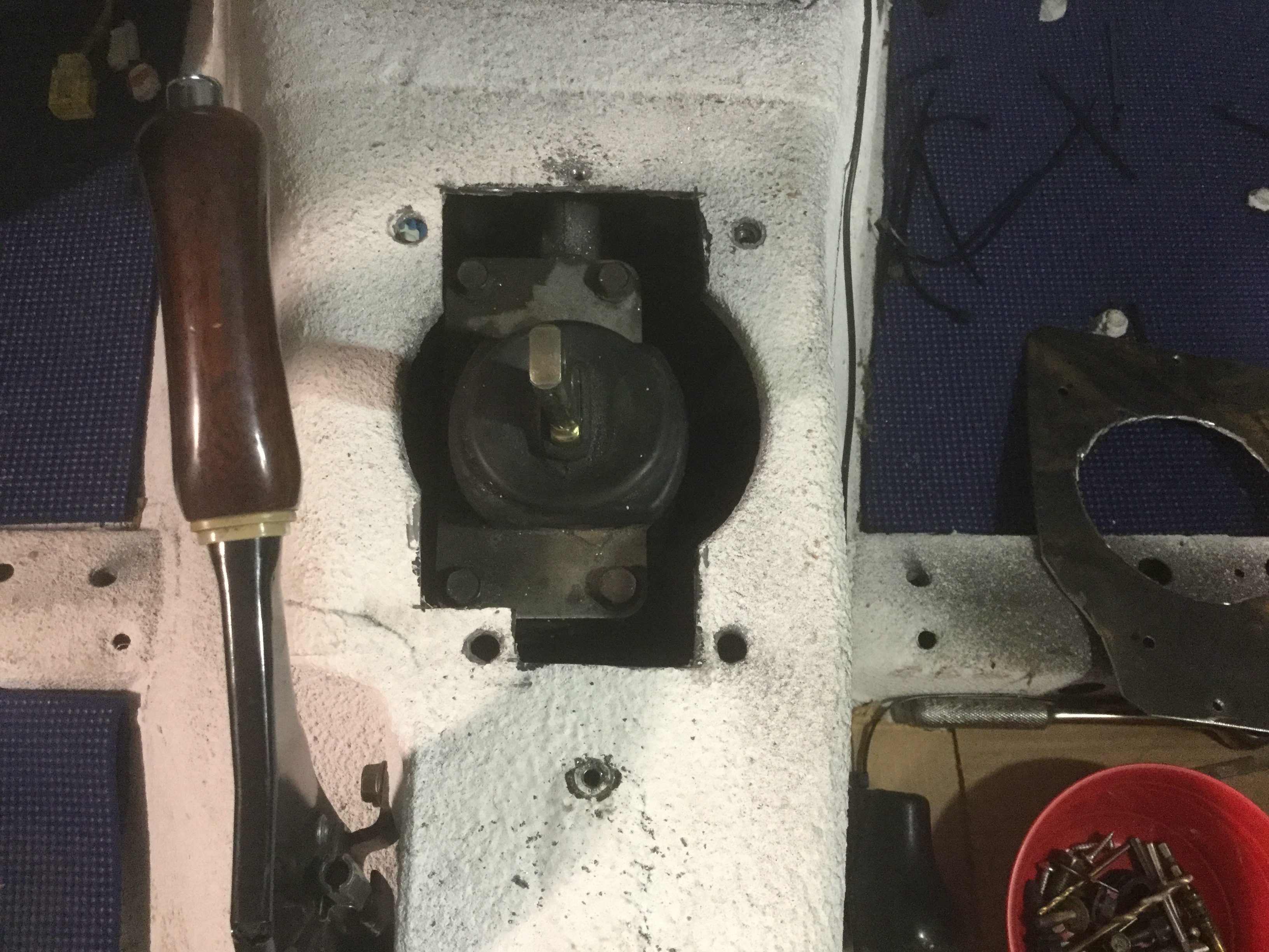
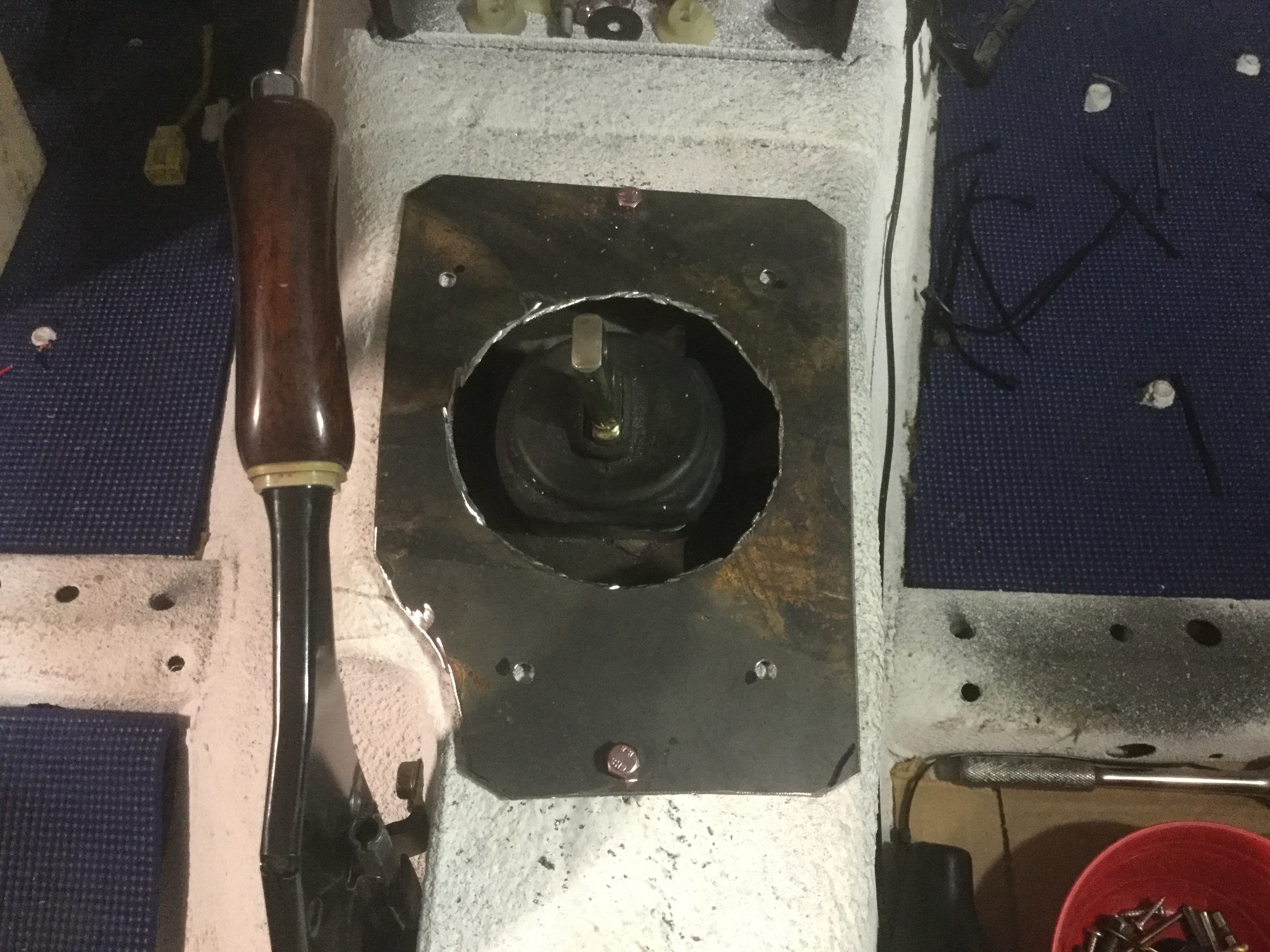
One example is a cover for the transmission opening in the tunnel. The opening is trimmed as shown in the picture because someone pointed out that unless it is trimmed, you will not have access to the shifter plate unless you drop the transmission. This is a big deal when you change the transmission fluid because you add the new fluid by removing the shifter cover (not thru the level hole). Also, if you ever decide to change out the shifter you need access to the top plate and four bolts.
Edit;
This modification has been a huge help and one I would recommend anybody doing a T56 swap do.
Can't even tell you how many hours of time this has saved me over having to remove the transmission to change out the shifter.
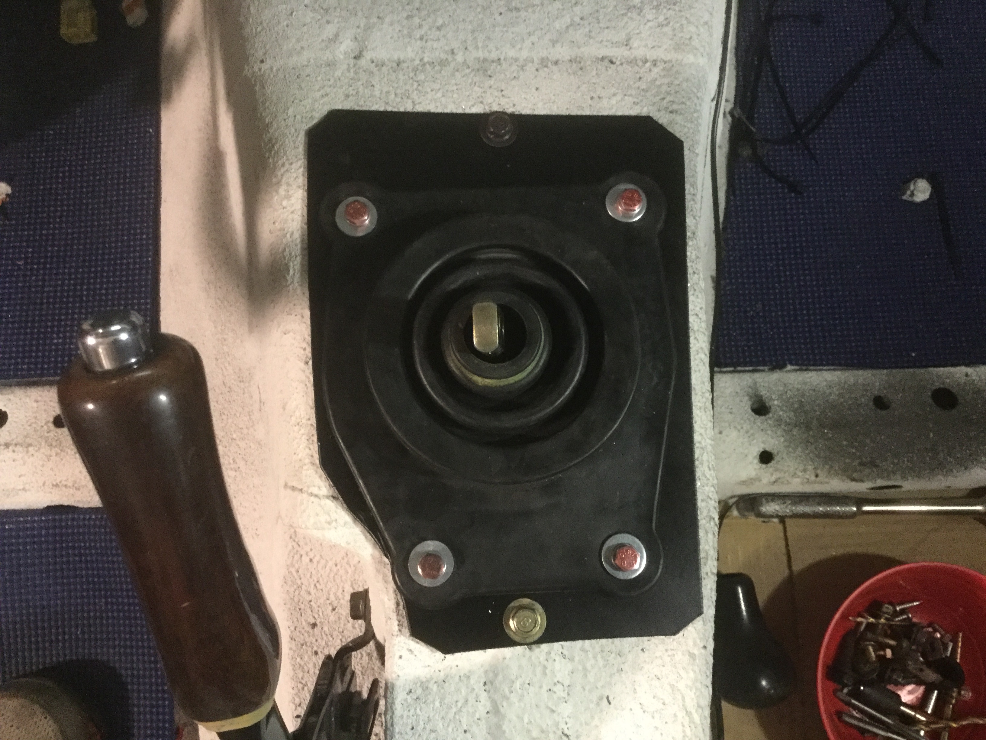
It just takes a simple plate with a hole centered on the shift lever. The hole looks a bit scabby because of the method I used to cut the hole. Don't have a cutting torch unless I borrow one so the hole was cut with a cutting wheel by making a bunch of short straight cuts that are connected and then cleaning it up as much as possible. Gets the job done but not the prettiest solution. Rather than struggling with nuts on the underside, I went ahead and tapped the holes in the plate.
Because it was in excellent shape I decided to reuse the Miata rubber boot. It should fit properly under the console. The Z28 boot was supplied with the transmission but it just looked too large and I was worried there might be interference problems. A coat of black paint to keep the plate from rusting in the future and a few bolts and it looks decent. For the final assembly I also put a bead of Silicone sealer to keep any moisture from seeping into the passenger compartment and causing problems with the carpeting.
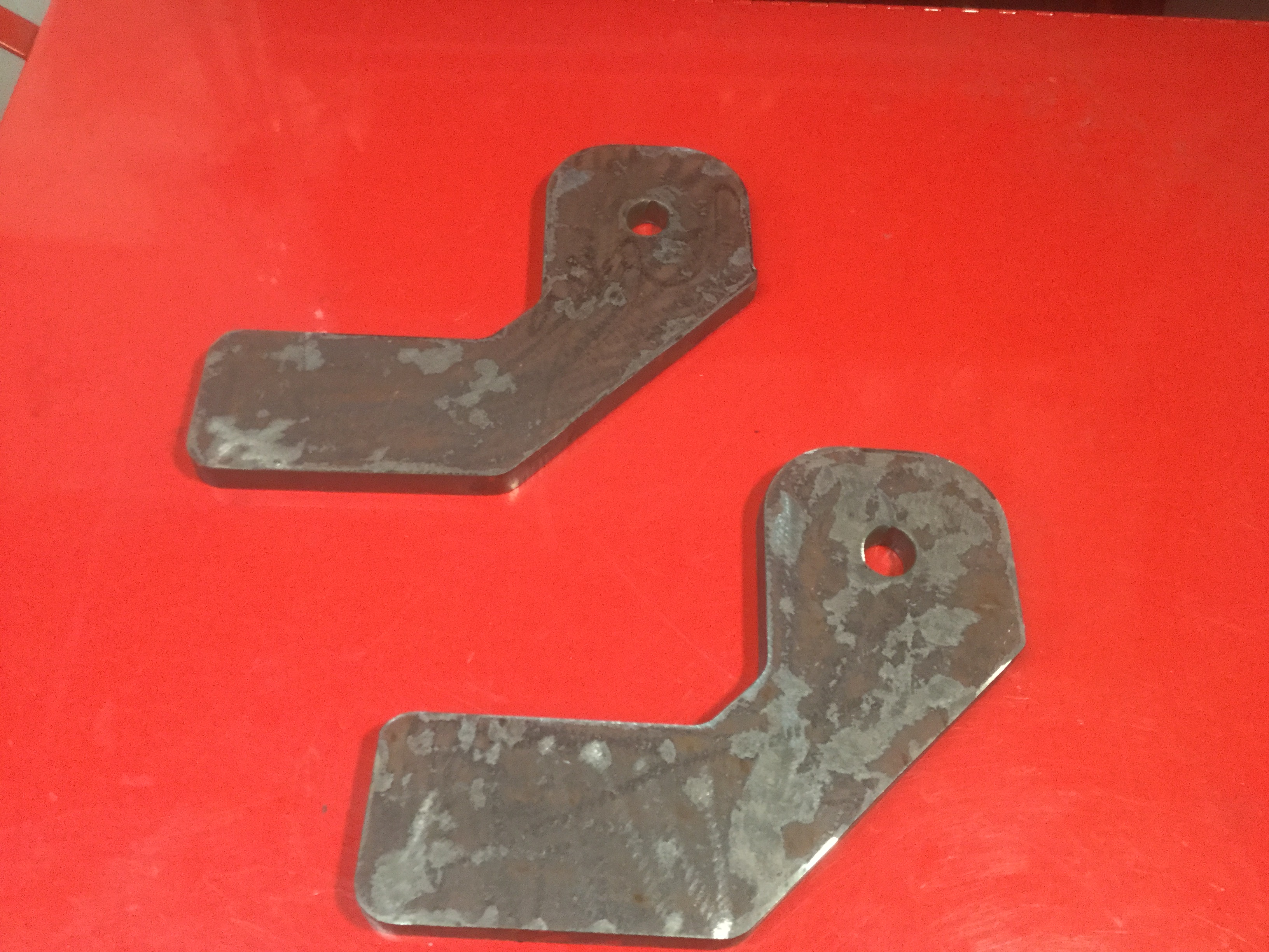
Another little project that is not directly involved with the swap but falls under the category of "might as well do it while the car is apart" is to add the capability to flat tow the car if desired. For me, it is mostly of an easy way to get the car home if it breaks down.
To that end I have fabricated two brackets that weld to the front cross member of the car. Since I work at a steel fabrication shop and we have a plasma burning table I got the operator to cut me a couple of brackets while he was cutting some other stuff. They ended up being 1/2" thk., which is thicker and heavier than necessary but will get the job done really well.
Edit;
Each of the brackets should have gotten a second hole installed towards the bottom to facilitate the installation of a safety chain mounting point.
Because I am already trimming the cross member to gain clearance for the Corvette cold air intake, the bracket welds in place fairly easy. In hind sight I could have made the contact surface a bit larger and welded them directly to the car but my original plan was to weld them to the replacement support angle that re-connects the two sides of the framework. After mocking up the cross support it became clear that the brackets need to be as far away from each other as possible to get good triangulation for the actual tow bar to attach.
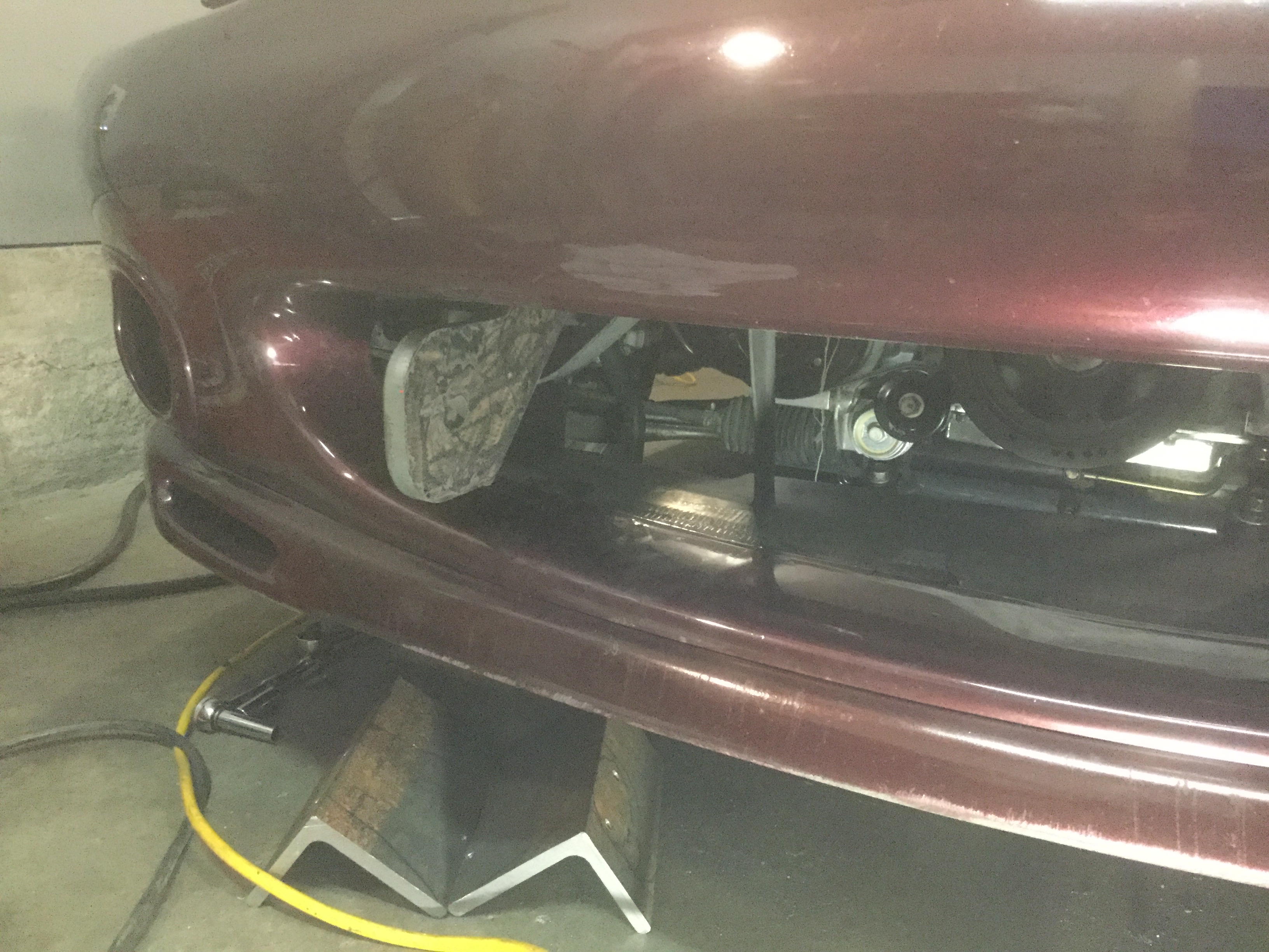
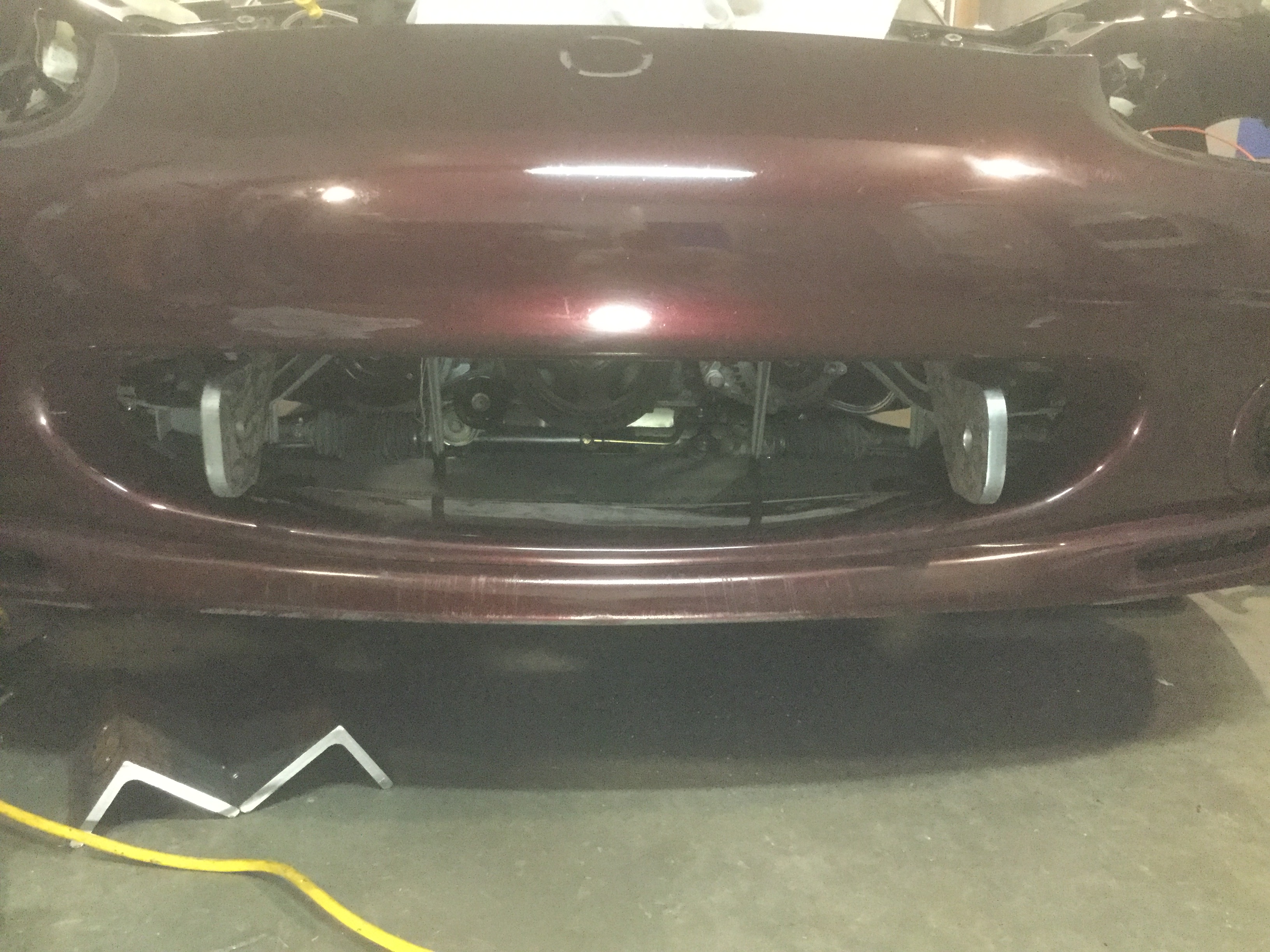
My next worry was how well the front bumper cover installs with the additional brackets in place so I did a test fit while the brackets were just tacked in place. It works out very well because the location allows the cover to slide in place real easy without any contact at all.
It all seems to fit up properly but I need to remove the cover and install the cross angle and weld everything together. Since I am waiting on the cold air kit from Flyin Miata, it seems best to not actually weld everything until test fitting the intake.
The other thing I did to be able to tow the car is to add a little black box with to wire connection that lets the car tail lights mimic trailer lights but not back feed the electrical system. Checked on the internet and bought a kit for about $40. Did not take any pictures but it installed real easily by tying in to the wiring harness that sits right behind the driver's seat. Spliced in the box connections per the instructions and everything works out really nice and clean. Run the 4 wire bundle up to the front of the car and make sure to have enough length to hook to the tow vehicle connection. Did not take any pictures but the electrical stuff installed nice and easy. The box location ended up being right next to the relay and breaker that were previously added for the upgraded fuel pump.
I was curious about the tow hooks too, did you cut out the mounts for the stock front "baby teeth"? These seem pretty beefy (heavy). Hopefully you are not planning to get towed home too often ;-)
I have read that towing any car with a T56 is bad for the trans. Might have to disconnect the driveshaft?
If I tow it very far the driveshaft will get disconnected. From what I understand from the LS1Tech forum, the T56 is fine for towing 50 miles or less. During the assembly process I did trim some from the rear differential nub that slides thru the center of the driveshaft rear connector specifically so that the driveshaft can be removed without pulling the differential.
I was curious about the tow hooks too, did you cut out the mounts for the stock front "baby teeth"? These seem pretty beefy (heavy). Hopefully you are not planning to get towed home too often ;-)
Not sure what you mean by "baby teeth".
As part of the modification for the Flyin Miata cold air intake kit, the front cross piece that the bumper cover bolts to gets trimmed to allow room for the Corvette Plastic Intake. I simply cut a bit wider on the same piece of sheet metal and then welded the towing brackets in place before installing the replacement angle support.
Yes, the brackets are quite a bit thicker than necessary but that is what the shop had on the burning table when I needed the brackets cut. Could have just as well gone with 1/4" or 3/8".
No, I am not planning on getting towed home often but did want to plan for the possibility of flat towing the car in the future.
Sort of a "Might as well do it while messing with that area of the car".
At one point I debated having a bolt on bracket so that nothing would be visible when not being used. If I don't like the look when it is all done, that is still an option.
Just a small amount of progress over the weekend.
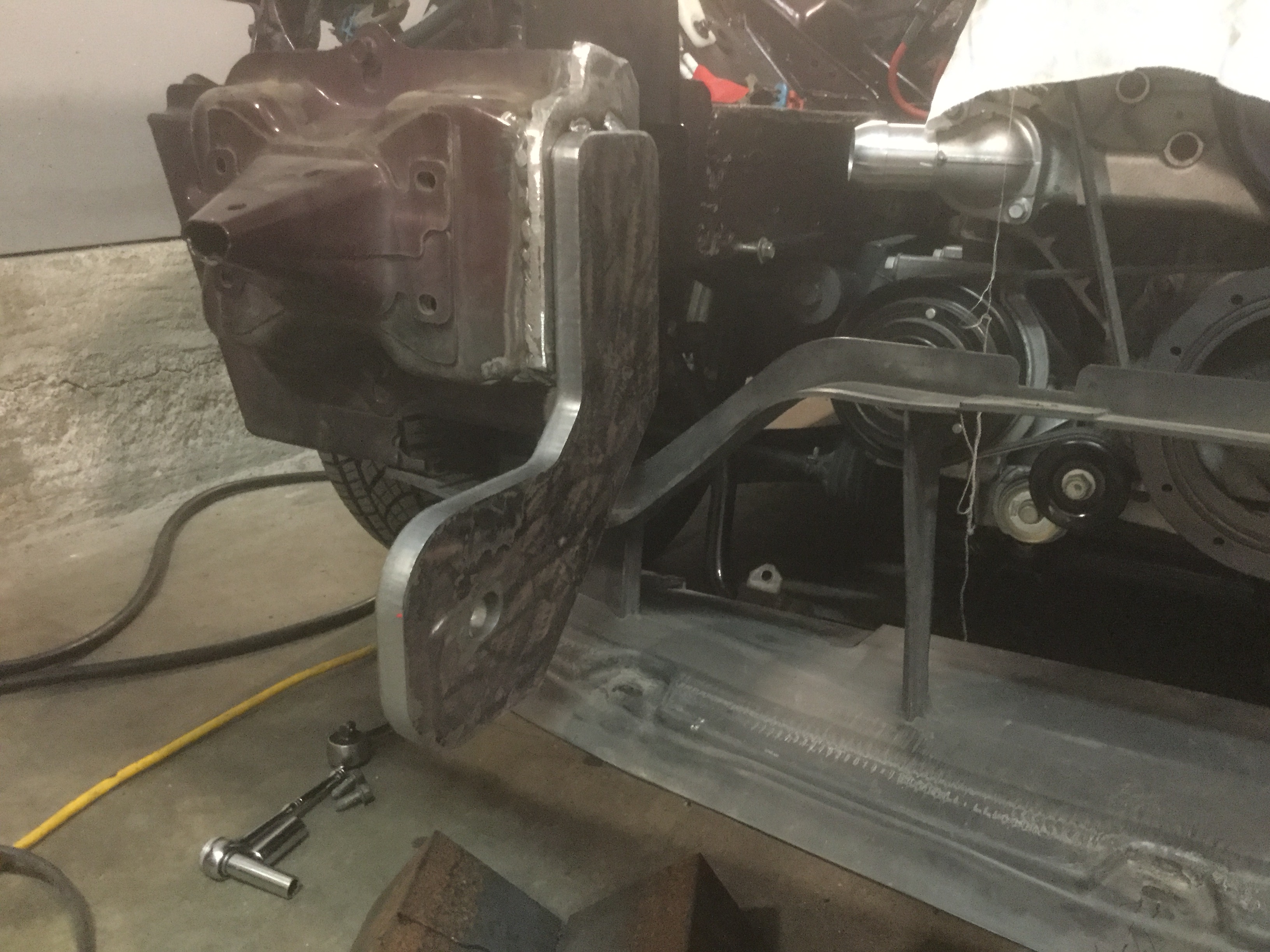
The factory front sway bar mounts will not work with the CTS-V front accessory drive because the harmonic balancer tries to take the same real estate as the sway bar.
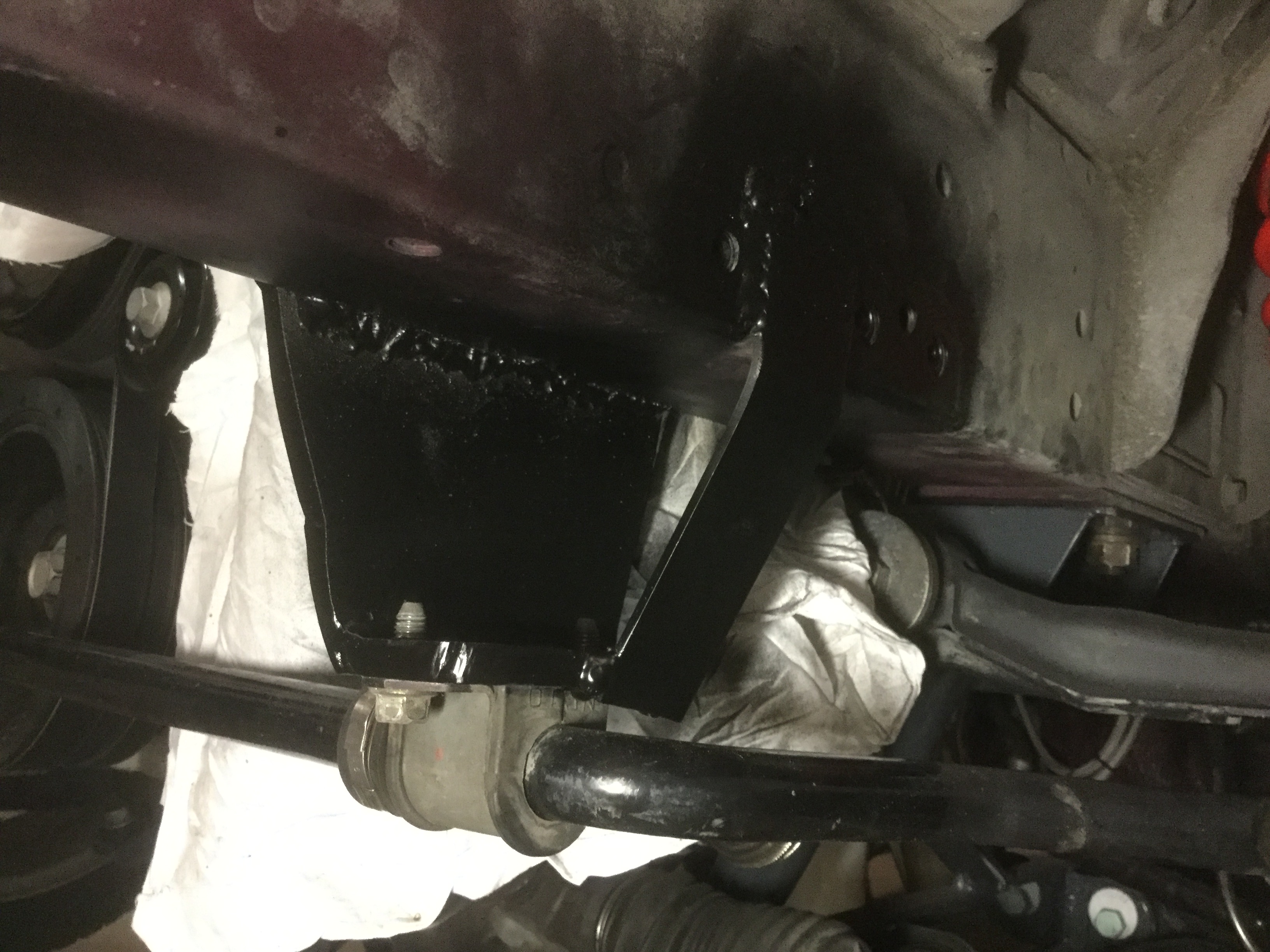
To that end I fabricated new mounts that move the sway bar just enough further forward to clear the balancer with 3/8" of clearance. Could have bought beefed up mounts or even a different sway bar from Flyin Miata but doing custom mounts is really simple. Just a couple of short pieces of 4" x 3" angle, with two mounting holes in each welded to the front subframe. Used a piece of flatbar to box in the angle just to make sure it stays where it belongs. The area underneath the front subframe needs to stay open so that a bolt attaching the upper a-arm can be removed if the need ever arises.
Covered it with some black primer/paint to keep it from rusting but it will eventually be the same color as the rest of the car. Just need to finish up the last bit of welding after the cold air kit arrives. The black paint makes it tough to see in the picture. The white rag is just to keep paint splatter off other stuff.
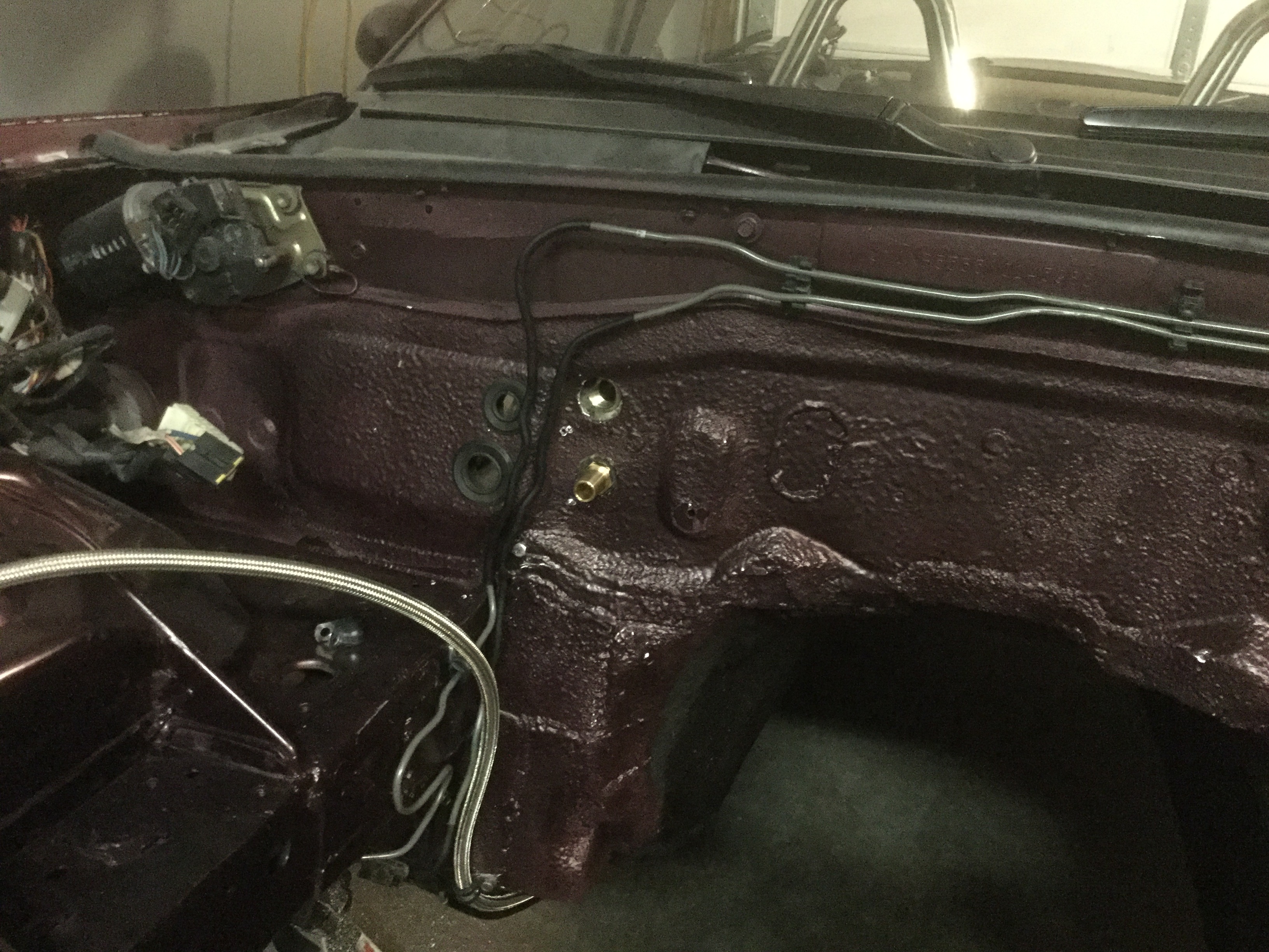
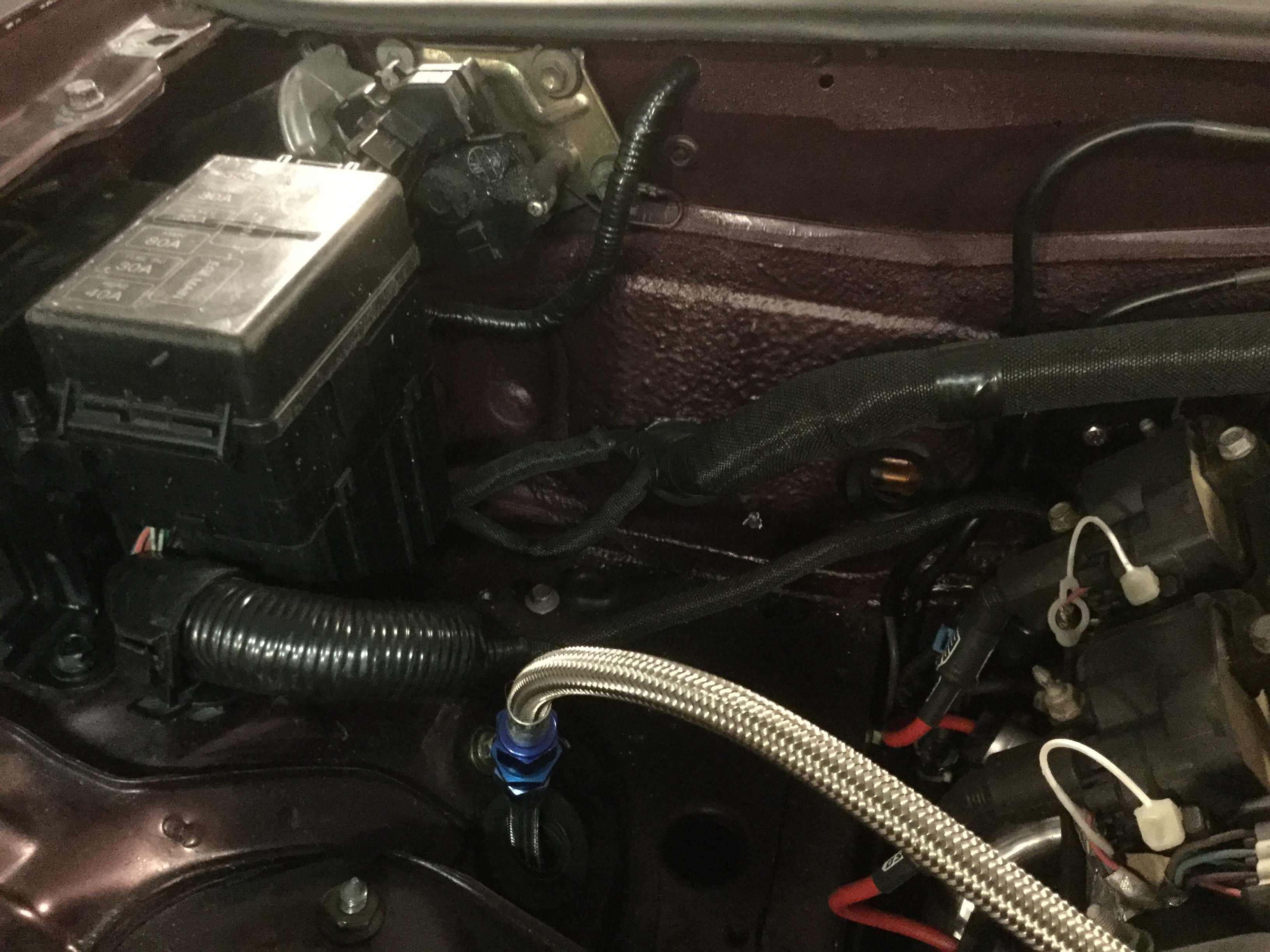
On the routing of the fuel line, this picture shows where the line ended up coming thru the fenderwell and into the engine compartment. The placement gets plenty far enough away from the header heat. I also had to get a coupling and 12" line extension piece because the Flyin Miata hose is too short for the routing I utilized. If my car would have had ABS, there would have been some hardware right int he same area I picked to run the line but in that case the fuel line had several other good places it could have been located.
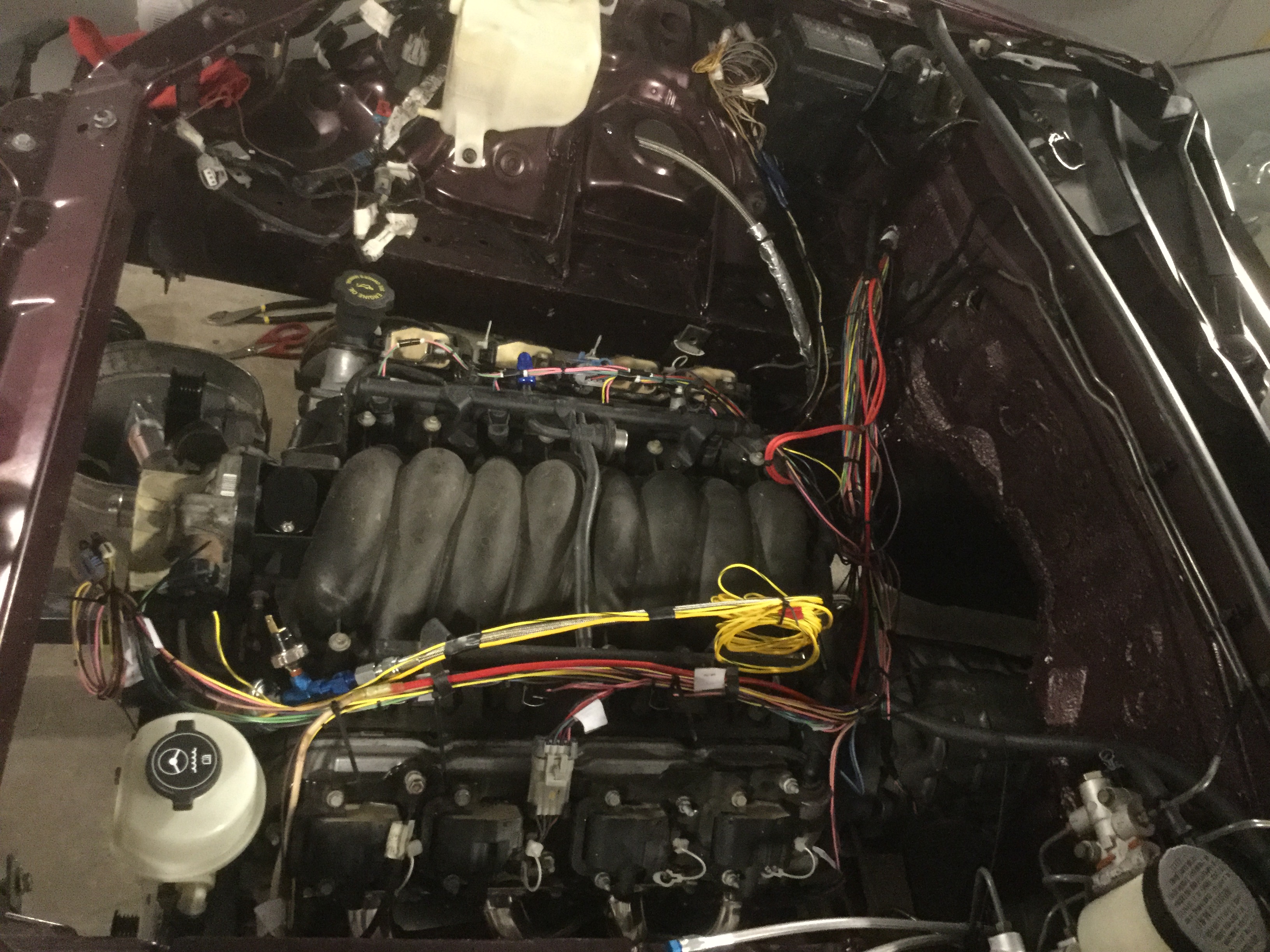
The engine compartment wiring is 99% cleaned up and has sleeves installed and taped. Rather than use the old plastic stuff that came on the old LS1 harness I utilized new Painless Wiring sleeves that I got with the electrical harness. They look like they will hold up way better than the factory plastic stuff because they are some sort of heat resistant weave material.
This is a view where I put the main harness thru the firewall and into the passenger compartment where the ECU is located. You can see a short piece of factory plastic sleeve on the left and the newer weave stuff on the right. I ran short of the new stuff and so had to run this one piece of old stuff next to the fuse box.
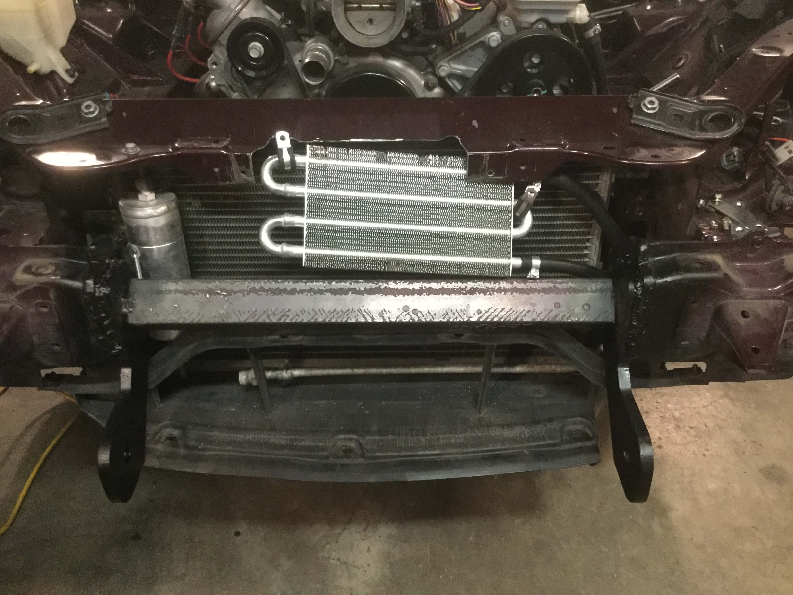
The air conditioning radiator and power steering radiator are roughly installed where they will be located but neither have brackets attached so that they can be moved as needed when the actual radiator and cold air intake gets installed, hopefully this weekend. I needed the power steering radiator to be connected so that I could start the car. Didn't want to run the risk of starting the car with no fluid in the power steering pump. You can also see the tow brackets and bumper angle support that still need final welding in place after checking fitment of other front end stuff. As somebody else mentioned on another build thread, Summit Racing and JEGS both have house brand small radiators that work real well for power steering radiators. I think the one I got was less than $30 with the necessary high pressure hose and clamps.
In this picture you can see the plastic air inlet piece that hooks to the plastic front cosmetic cover with the towing brackets. Look at how everything fits together and you can see why I removed more of the front sheet metal support because it allows the towing brackets to go in their location without the need to trim anything out of the way.
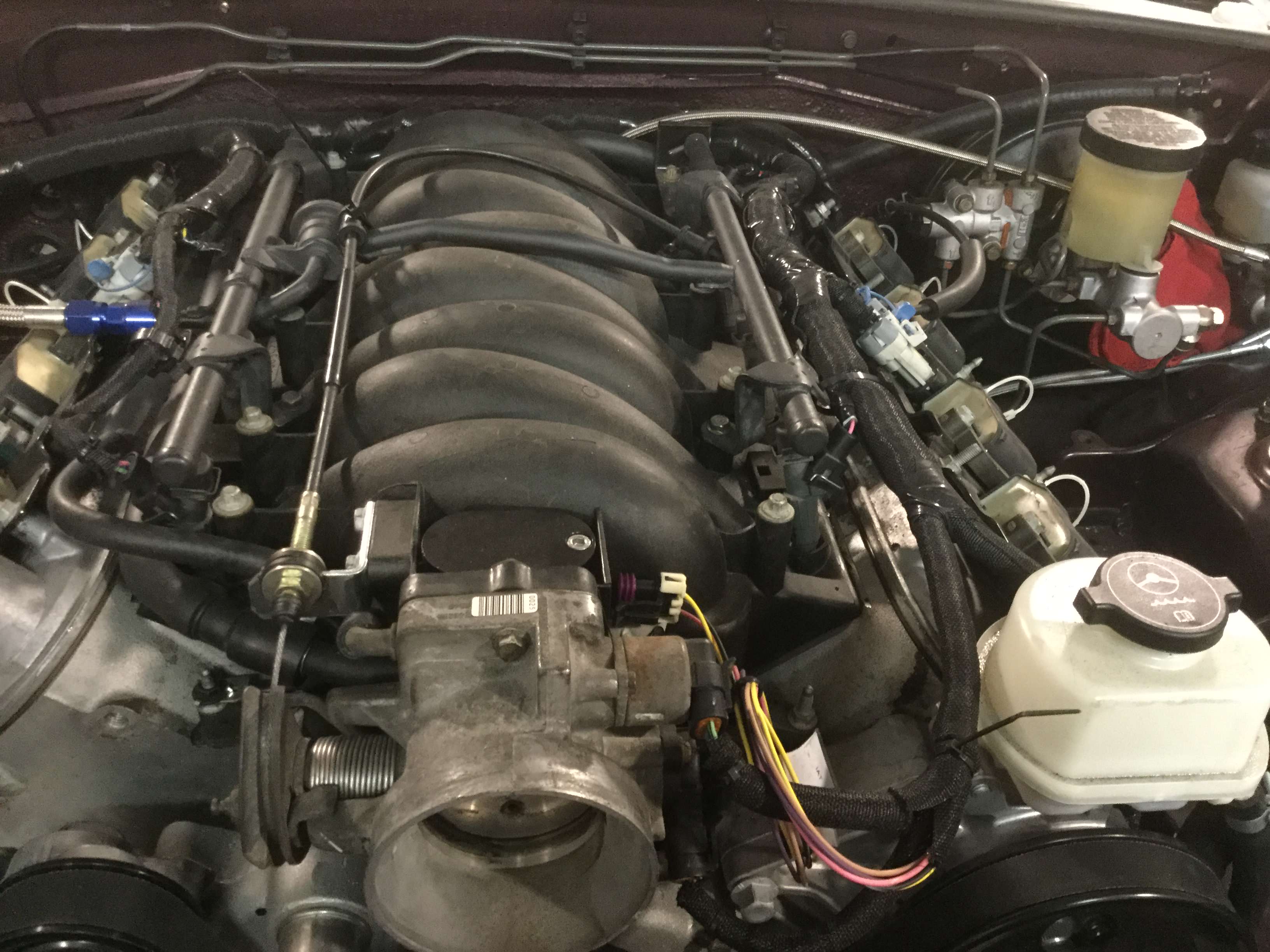
This picture shows the engine wiring harness all installed and wrapped and taped and ready for the Corvette engine covers to be installed. You can also see the little throttle cable bracket that I fabricated from a piece of angle. It works just fine but as mentioned in a few other threads, the pedal will only open the butterfly about 80% of the potential movement. Not sure how much difference it will make and if I want full movement I will have to switch out the throttle pedal and cable because the Miata pieces simply do not have enough travel.
Edit:
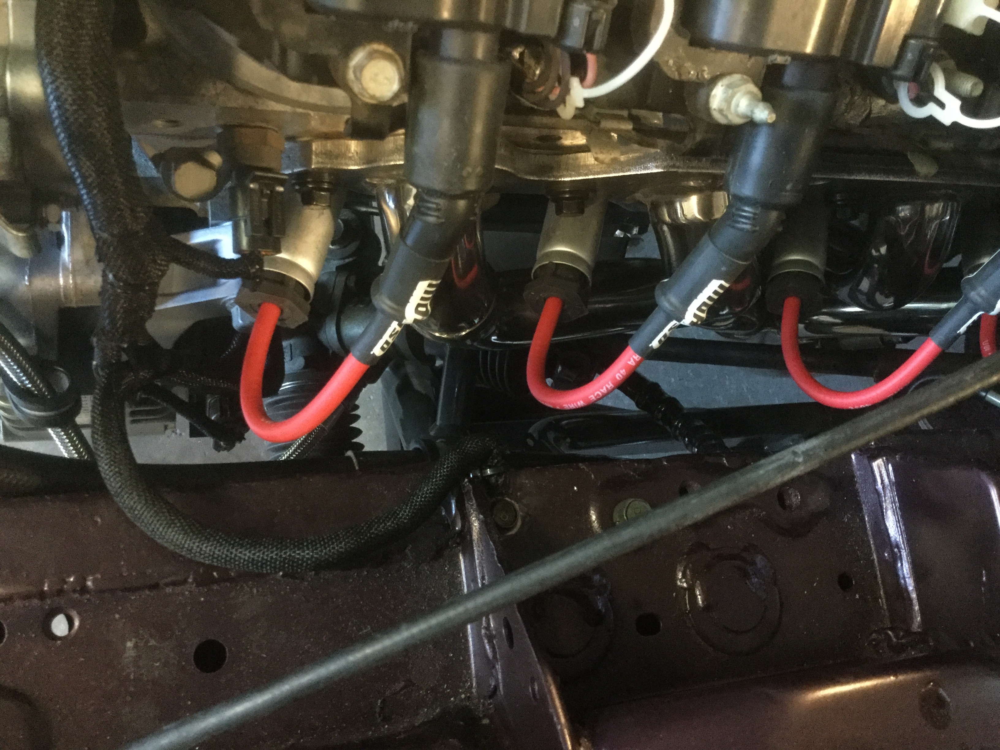
After the initial month of driving the car got the engine and transmission removed to fix several issues (transmission upgrade and rear main seal replacement). As part of putting the car back together I removed the cover sleeves and taping from the wiring harness and reworked it to raise the main section of the wiring away from the engine heat and mounted it higher on the firewall.
There is plenty of wire length available so there is no reason to make the drops as short as I did the first time.
The second time I zip tied the main harness up near the brake lines and routed the drops with the engine sitting about 6" lower than it's final resting place to give a reasonable amount of slack to each of the drops.
Live and learn.
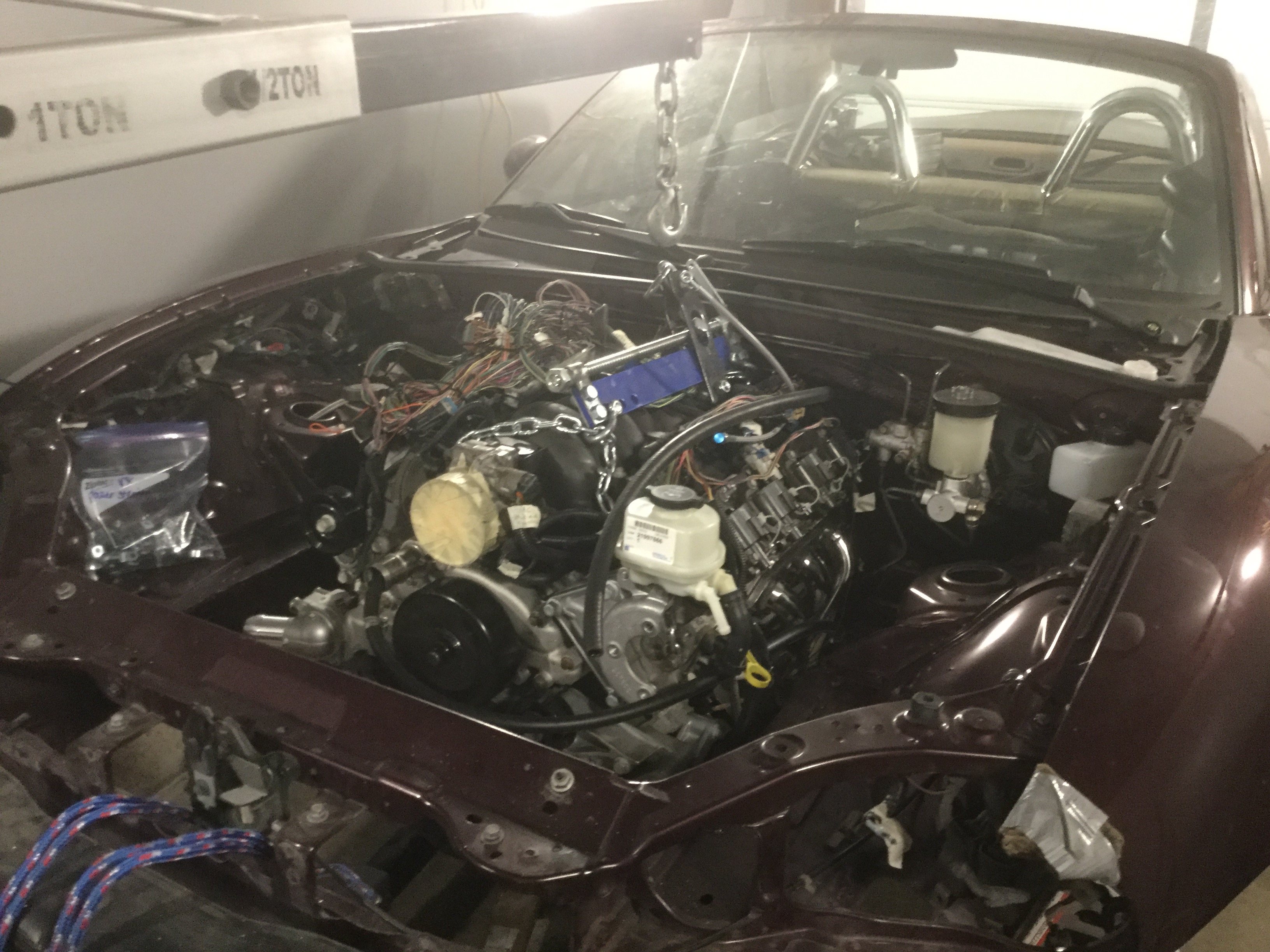
You can see the difference between the next two pictures.
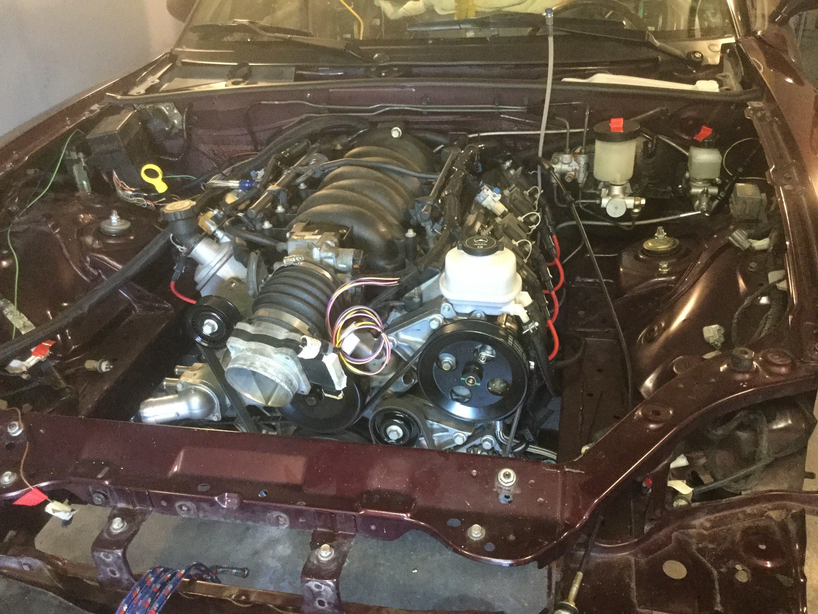
The first picture is the final engine bay.
This picture is the initial engine bay as the wiring harness was originally done.