
2000 Miata V8 conversion with 2000 Z28 & 6 speed & Getrag


Thread Starter
V8 Miata Enthusiast
Joined: Apr 2016
Posts: 412
Likes: 30
From: Tulsa OK
The next small project I decided to tackle is re-routing the heater core plumbing to move the firewall hole locations from the drivers side to the passenger side in order to keep the engine bay looking as clean as possible and to keep engine bay water hoses far enough away from the hot engine.
Some of the other build threads show the heater core and plumbing as being copper but for my 2000 the core and plumbing is Aluminum.
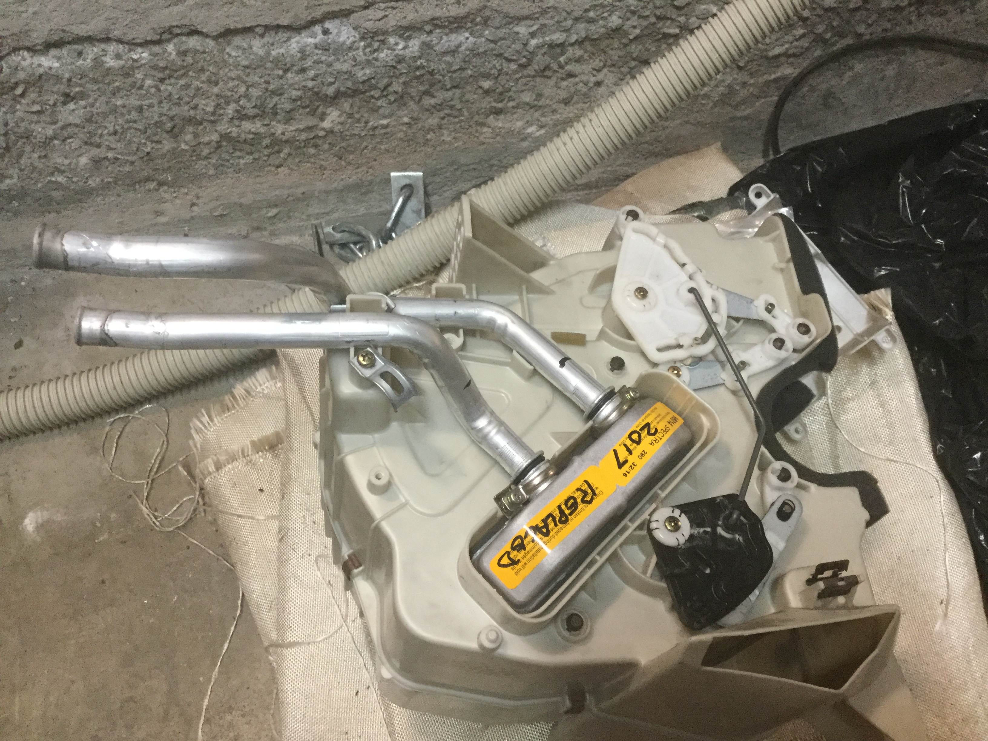
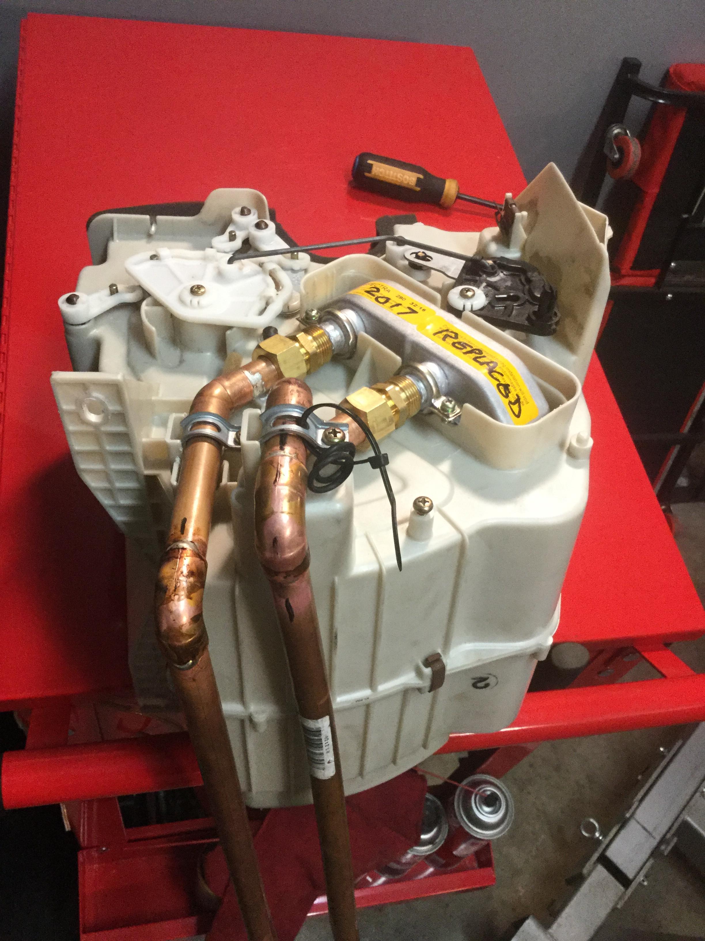
After doing some checking around I found it is common to solder aluminum to copper, which makes me feel comfortable doing a slip joint to connect the two materials and allow me to make a hard line which IMO is the superior long term solution over rubber heater hose. The lines run between the dash and the firewall in the passenger compartment so getting to them to repair a leak down the road would be VERY difficult and probably require removing the dash. A trip to Home Depot got me various fittings and tubing and solder to do the project. One thing of note when measuring the tubing is that the Aluminum tubing is not exactly the same diameter as 1/2" inside diameter copper tubing but it is just slightly larger and I was able to file down the outside diameter of the aluminum to press fit into a copper fitting. Another thing I included is a joint that will unscrew so that the heater core can be replaced pretty easily if needed at some future time. I took the opportunity to install a new heater core even though my old one visually looked excellent. Home Depot has Aluminum weld rod that has a low enough melting temperature to use for the Aluminum to Copper joint and YouTube has several video's on how to do it properly. In the picture I already removed one Aluminum end where it attaches to the heater core. It is the short piece sitting between the two longer pieces. One other item I purchased is a length of black insulation to fit over the copper tubing in order to insulate the passenger compartment from the heat being given off by the hot lines. After purchasing the insulating piece I have been debating if it will work correctly for hot applications as the only place I have seen it utilized is for cold Air Conditioning tubing. My other option would be to get some 3/4" or 7/8" rubber hose to slide over the copper tubing after it is complete. Either should insulate the tubing well enough.
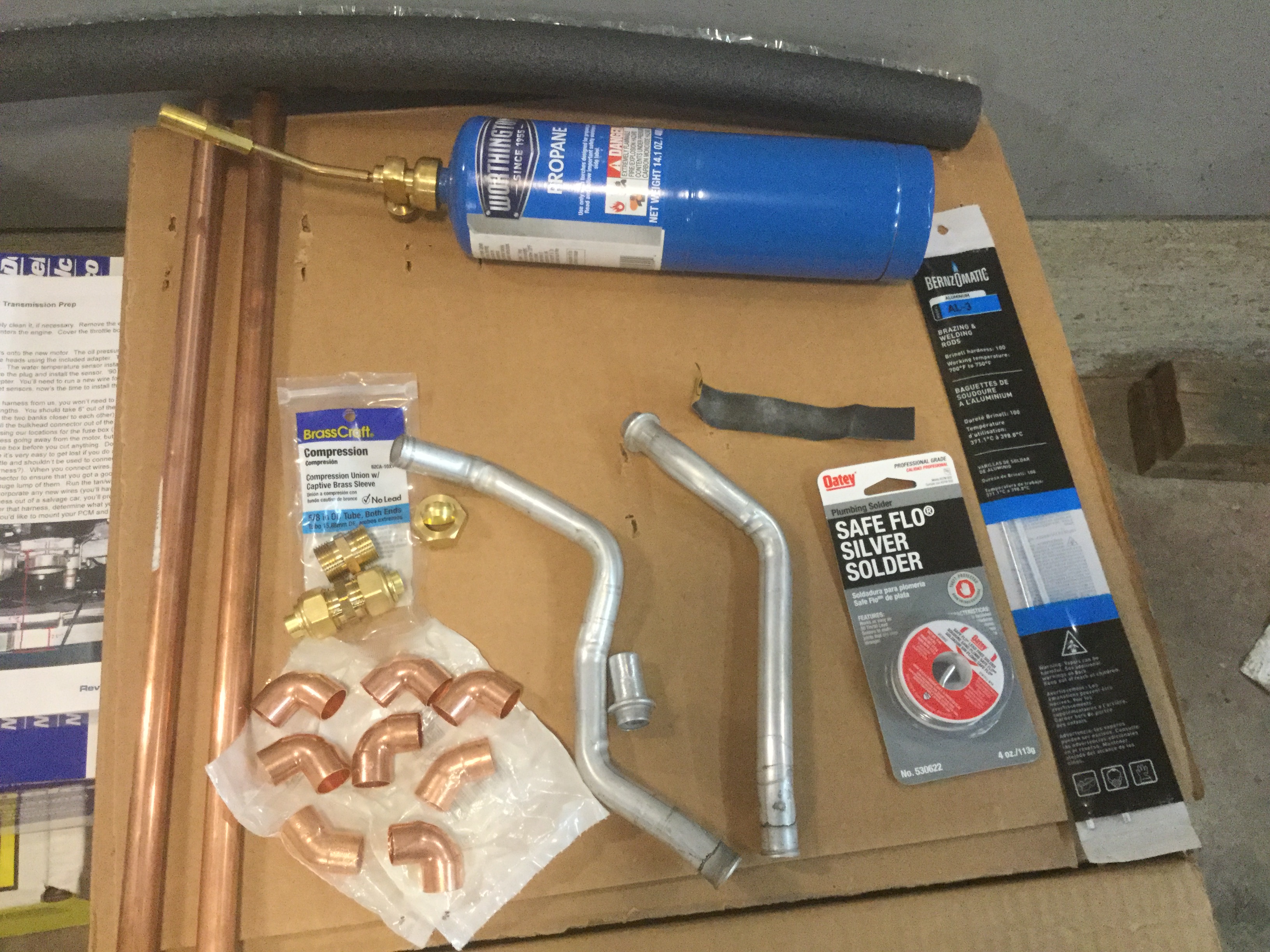
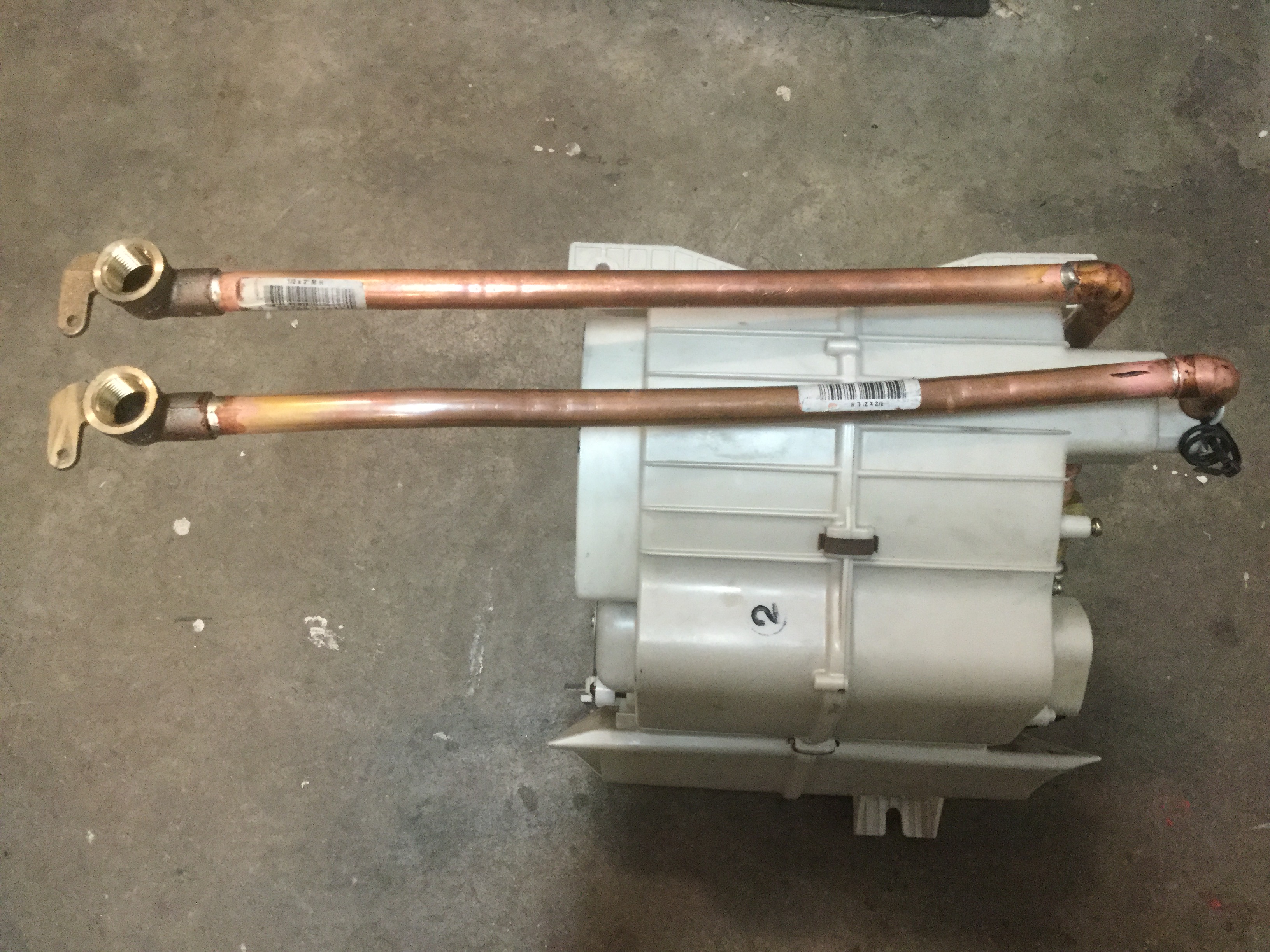
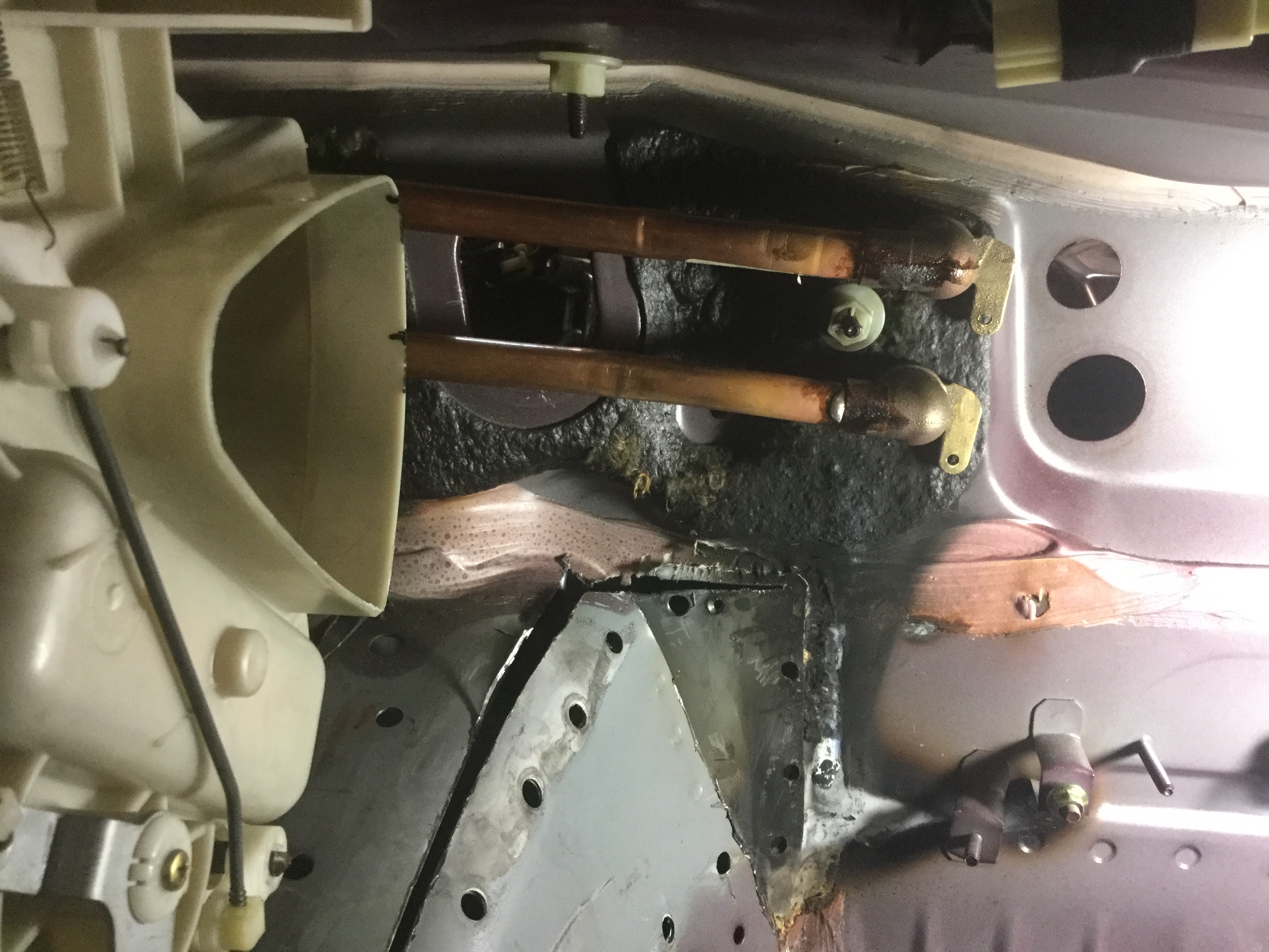
Got the dry fit part way done in this picture. You can see the removable compression fittings just above where the aluminum connects to the copper. Need to cut the long ends to length because at the moment they have excess length. Think I have a plan for getting the turns thru the firewall firmly attached in place but need to mock up the air conditioning connections thru the firewall before deciding exactly where to cut the heater hose locations in the firewall. Also, the elbows thru the firewall will be threaded on one side so that I can thread in some stuff to do a pressure test with water. I am thinking 30 pounds should do it since radiator caps have a pressure relief at 30 psi or less.
Making more progress on the heater line routing. Got some items to finish up where it goes thru the firewall.
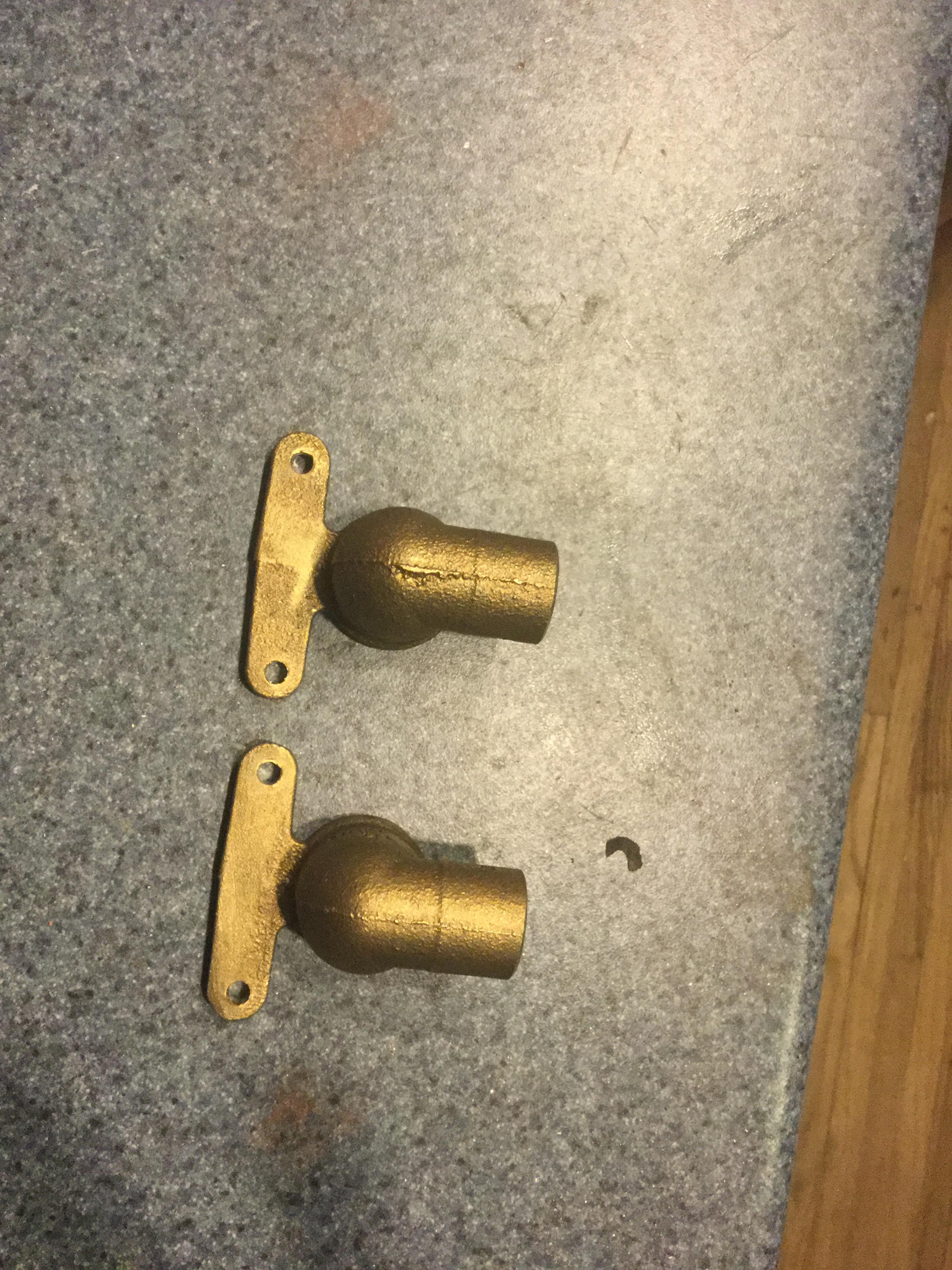
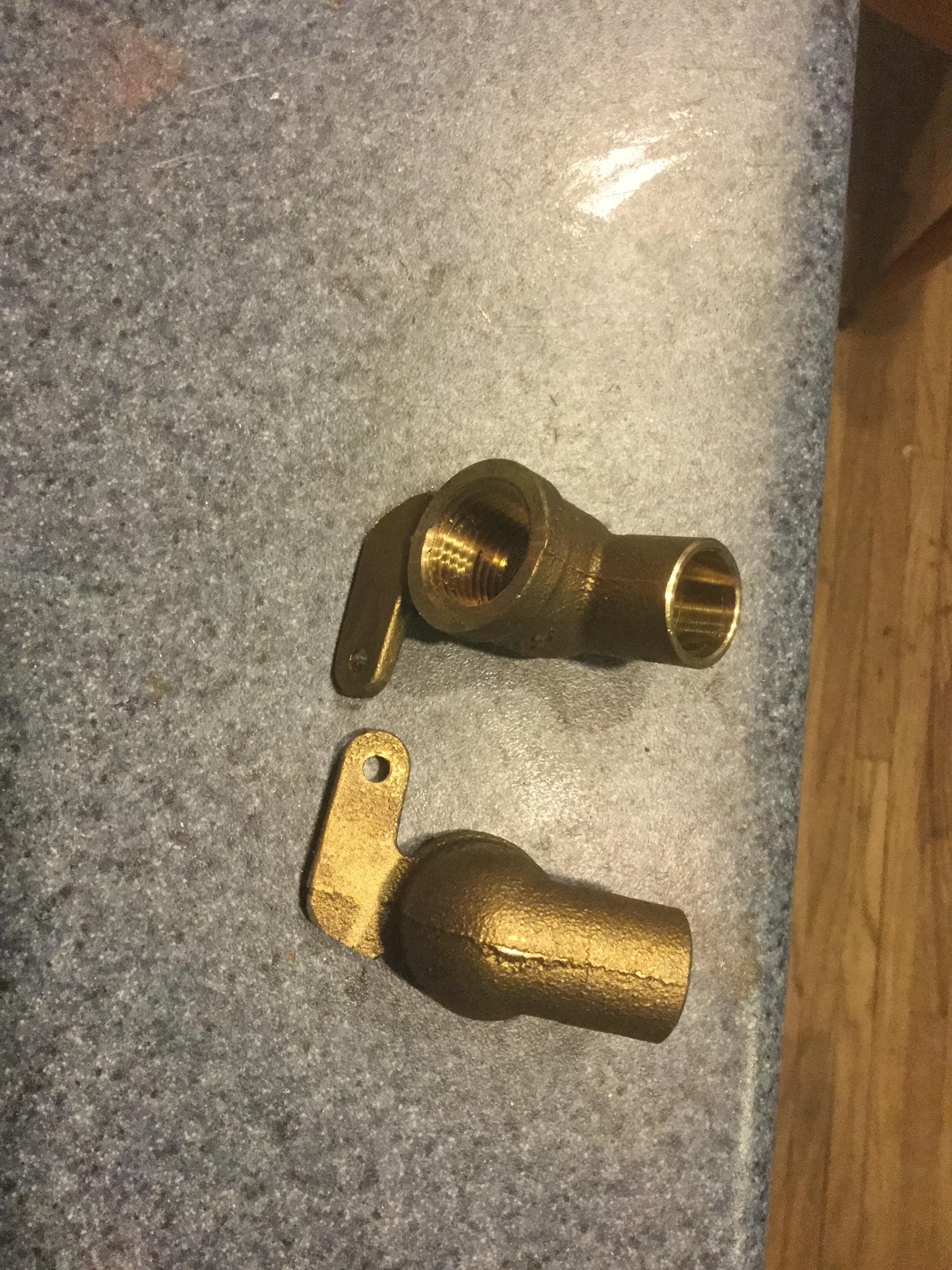
For me, it is important to be able to do a pressurized water test after finishing up all the copper tubing so a couple of elbows that switch to 1/2" pipe threads will be where the copper tubing goes thru the firewall. Bought two that had to be slightly modified.
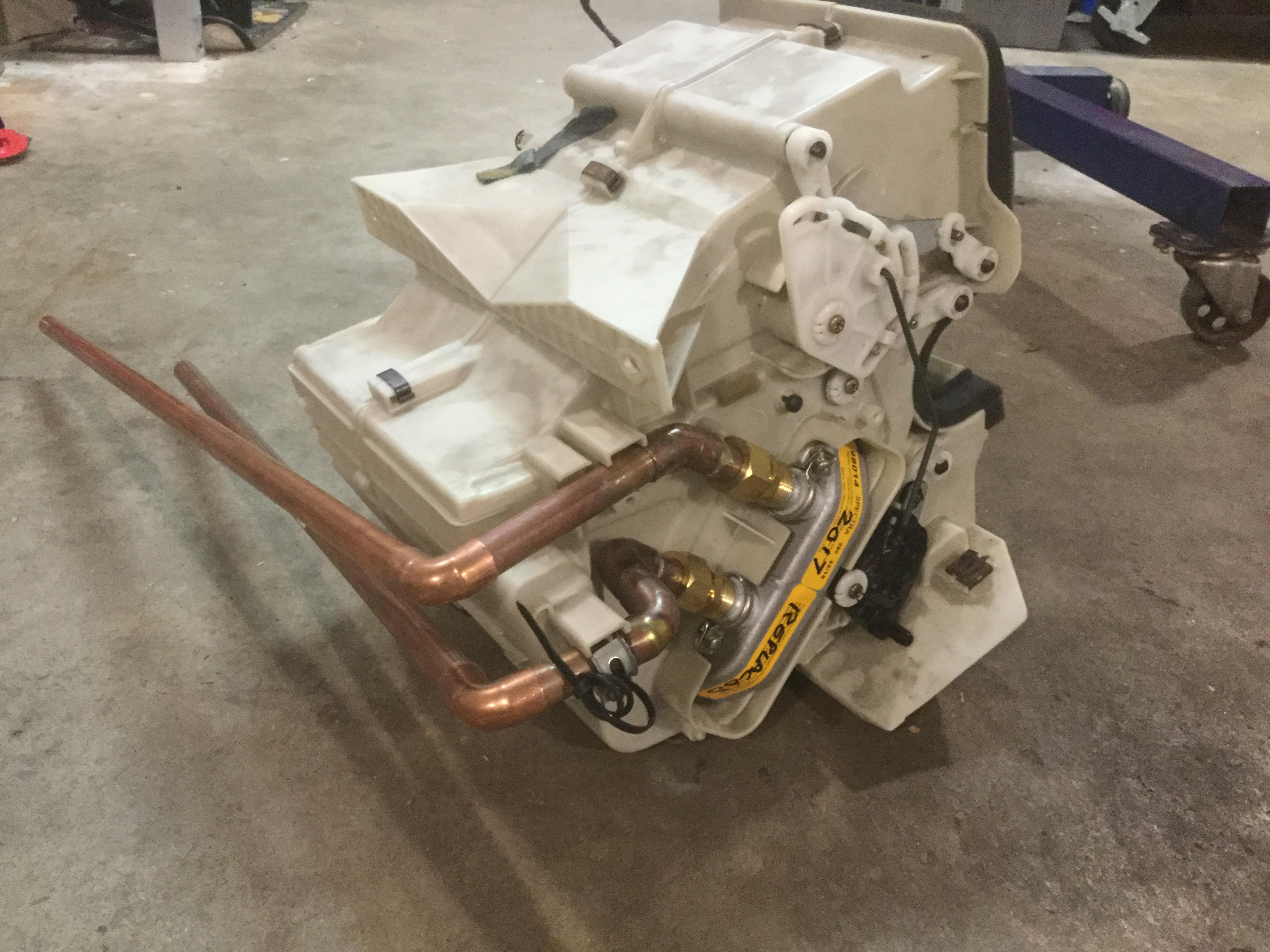
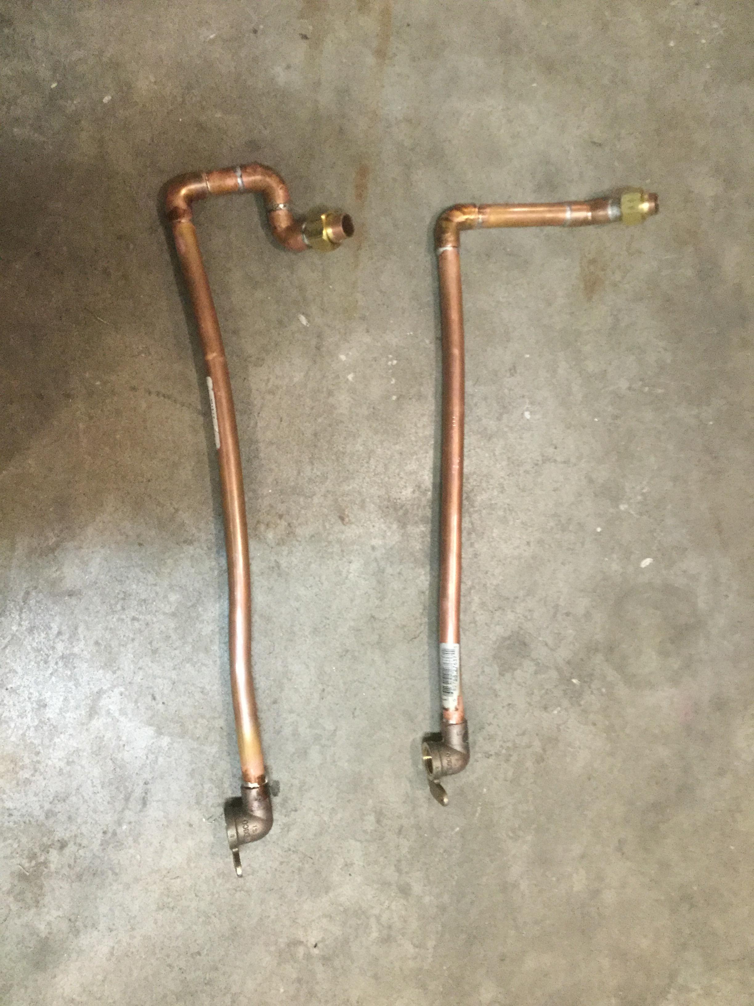
Finished the dry fit of the copper tubing and soldered it. Easy to see this is my first try at doing copper tubing. The two long tubes needed some bending to fit close to the firewall.
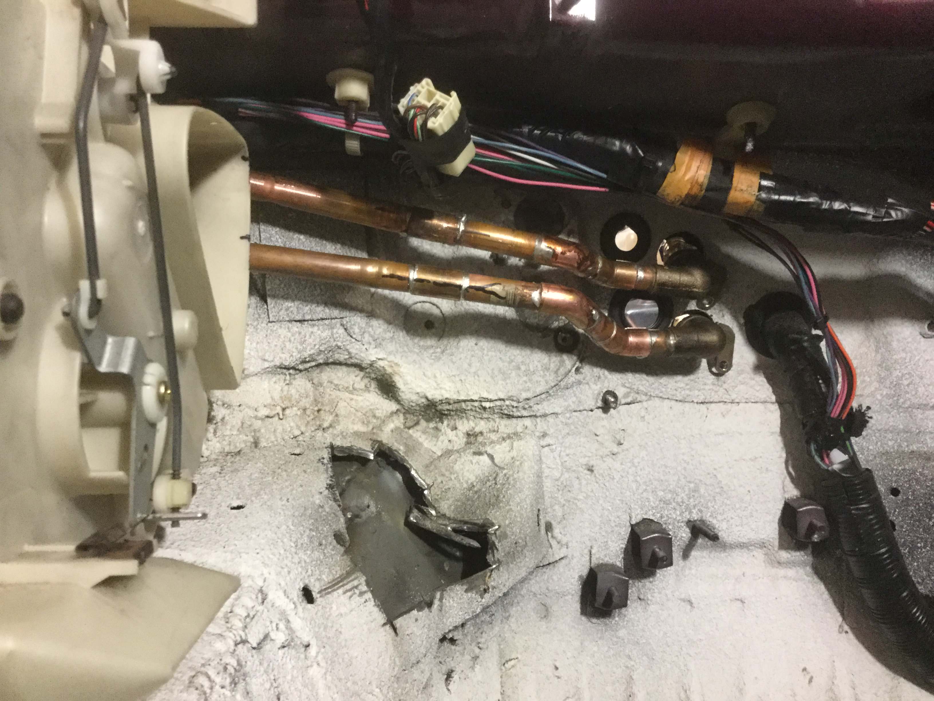
And finally, where I intend for them to go thru the firewall. It appears to clear engine components and is much easier because it stays to the left of the air conditioner tubing. The big hole where the original Miata wiring harness goes thru the firewall will be plugged with some sheet metal.
Now to work up the fittings to be able to pressurize the lines. I am thinking adapting to the quick disconnect on my hose that connects to my compressor. My plan is to fill the entire line and heater core with water, putting the threaded ends of the line as the high points then pressurize it with air. Debating on the pressure. Radiators have caps that pressure relieve between 20 and 30 pounds so a 35 pound hydrotest with minimal air in the system should sufficiently test the system.
The big hole where the original Miata wiring harness goes thru the firewall will be plugged with some sheet metal.
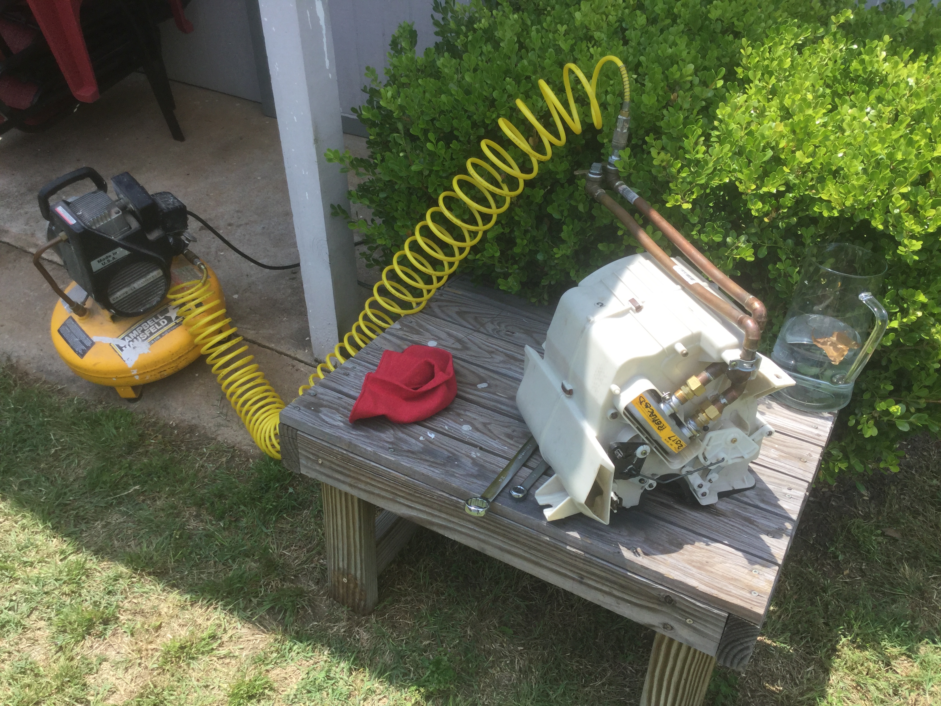
Well, I finally got around to water testing the coil and tubing.
It went well except for the location where the factory clamp attaches the tubing to the heater core.
That seal leaked just from putting water into the system even without pressuring it up. I got some silicon sealer and slathered it around that joint and let it dry for a day.
Refilled the system with water and pressured it up to about 30 pounds by completely draining my compressor then connecting the lines then letting the compressor to 30 PSI before turning it off. The heater assembly is ready to reinstall in the car.
Edit to update on trial fit:
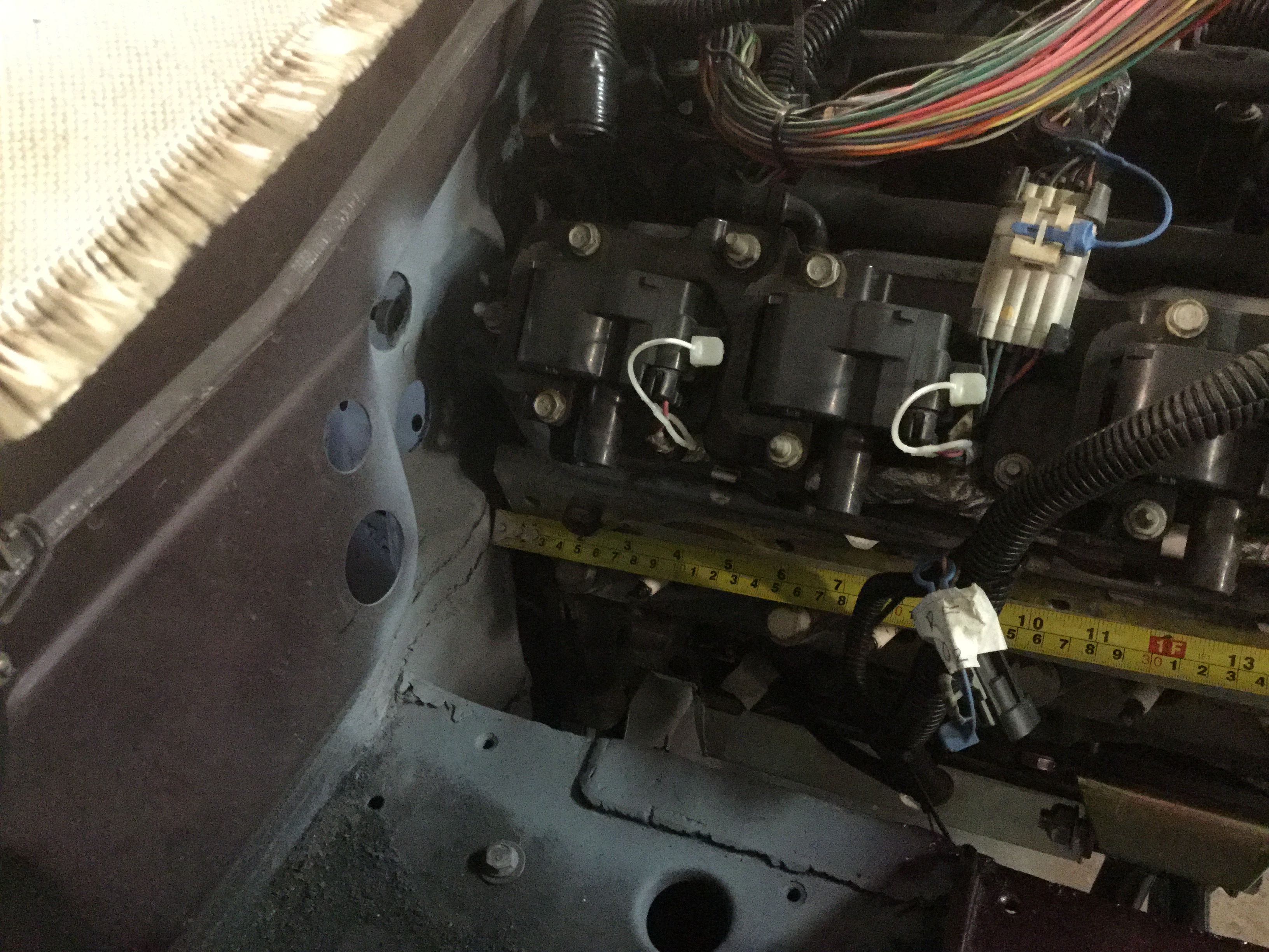
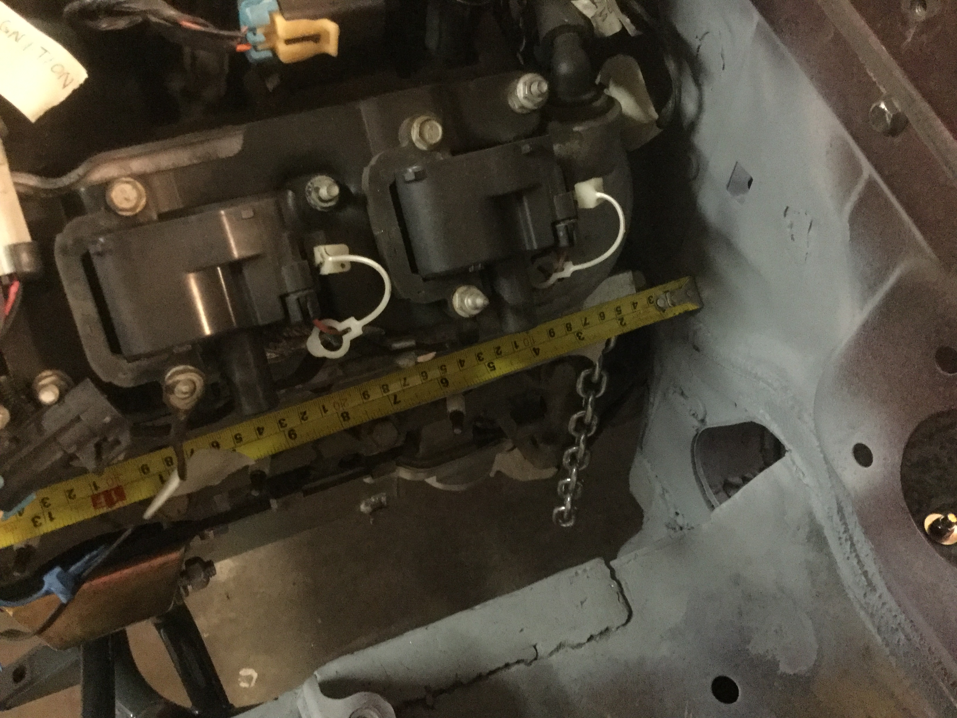
During the engine trial fit with all the fittings in place it looks like the firewall connections are simply too close to the rear most coil pack.
Going to do some looking for parts but barring some sort of saving item it looks like I am going to have to redo the tubing and go thru the fire wall on the left of the air conditioner connections. The Yellow Submarine build has the connections going over the air conditioning tubing and being located to the left of them but I thought I had enough clearance.
Teach me to not pay enough attention to clearances.
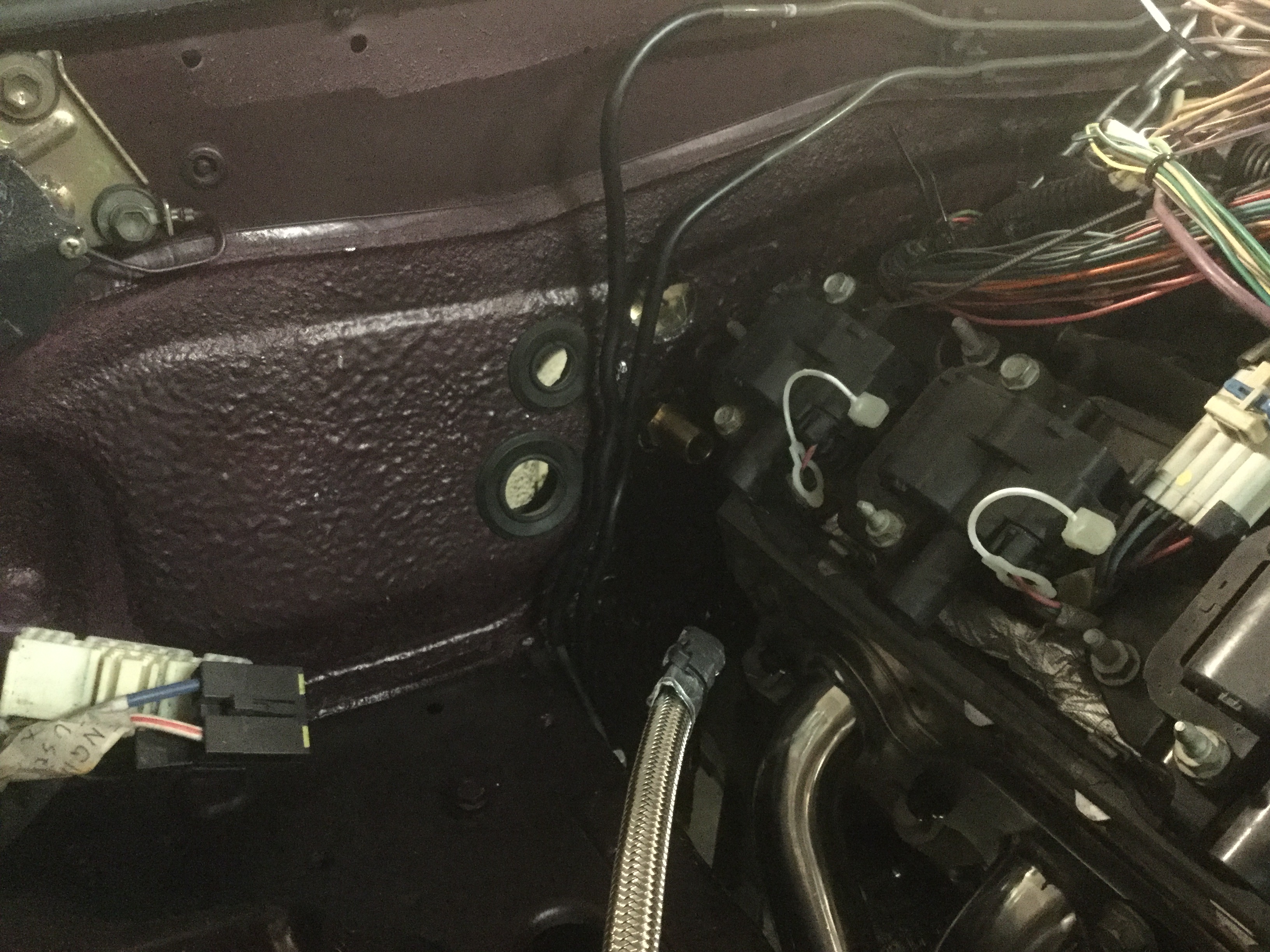
I re-routed the tubing to the passenger side of the air conditioning lines. A tight fit but it works.
As you can tell from a picture taken from the engine bay, the heater connections are visually to the left (passenger side) and lower than the air conditioning holes.
Some of the other build threads show the heater core and plumbing as being copper but for my 2000 the core and plumbing is Aluminum.
After doing some checking around I found it is common to solder aluminum to copper, which makes me feel comfortable doing a slip joint to connect the two materials and allow me to make a hard line which IMO is the superior long term solution over rubber heater hose. The lines run between the dash and the firewall in the passenger compartment so getting to them to repair a leak down the road would be VERY difficult and probably require removing the dash. A trip to Home Depot got me various fittings and tubing and solder to do the project. One thing of note when measuring the tubing is that the Aluminum tubing is not exactly the same diameter as 1/2" inside diameter copper tubing but it is just slightly larger and I was able to file down the outside diameter of the aluminum to press fit into a copper fitting. Another thing I included is a joint that will unscrew so that the heater core can be replaced pretty easily if needed at some future time. I took the opportunity to install a new heater core even though my old one visually looked excellent. Home Depot has Aluminum weld rod that has a low enough melting temperature to use for the Aluminum to Copper joint and YouTube has several video's on how to do it properly. In the picture I already removed one Aluminum end where it attaches to the heater core. It is the short piece sitting between the two longer pieces. One other item I purchased is a length of black insulation to fit over the copper tubing in order to insulate the passenger compartment from the heat being given off by the hot lines. After purchasing the insulating piece I have been debating if it will work correctly for hot applications as the only place I have seen it utilized is for cold Air Conditioning tubing. My other option would be to get some 3/4" or 7/8" rubber hose to slide over the copper tubing after it is complete. Either should insulate the tubing well enough.
Got the dry fit part way done in this picture. You can see the removable compression fittings just above where the aluminum connects to the copper. Need to cut the long ends to length because at the moment they have excess length. Think I have a plan for getting the turns thru the firewall firmly attached in place but need to mock up the air conditioning connections thru the firewall before deciding exactly where to cut the heater hose locations in the firewall. Also, the elbows thru the firewall will be threaded on one side so that I can thread in some stuff to do a pressure test with water. I am thinking 30 pounds should do it since radiator caps have a pressure relief at 30 psi or less.
Making more progress on the heater line routing. Got some items to finish up where it goes thru the firewall.
For me, it is important to be able to do a pressurized water test after finishing up all the copper tubing so a couple of elbows that switch to 1/2" pipe threads will be where the copper tubing goes thru the firewall. Bought two that had to be slightly modified.
Finished the dry fit of the copper tubing and soldered it. Easy to see this is my first try at doing copper tubing. The two long tubes needed some bending to fit close to the firewall.
And finally, where I intend for them to go thru the firewall. It appears to clear engine components and is much easier because it stays to the left of the air conditioner tubing. The big hole where the original Miata wiring harness goes thru the firewall will be plugged with some sheet metal.
Now to work up the fittings to be able to pressurize the lines. I am thinking adapting to the quick disconnect on my hose that connects to my compressor. My plan is to fill the entire line and heater core with water, putting the threaded ends of the line as the high points then pressurize it with air. Debating on the pressure. Radiators have caps that pressure relieve between 20 and 30 pounds so a 35 pound hydrotest with minimal air in the system should sufficiently test the system.
The big hole where the original Miata wiring harness goes thru the firewall will be plugged with some sheet metal.
Well, I finally got around to water testing the coil and tubing.
It went well except for the location where the factory clamp attaches the tubing to the heater core.
That seal leaked just from putting water into the system even without pressuring it up. I got some silicon sealer and slathered it around that joint and let it dry for a day.
Refilled the system with water and pressured it up to about 30 pounds by completely draining my compressor then connecting the lines then letting the compressor to 30 PSI before turning it off. The heater assembly is ready to reinstall in the car.
Edit to update on trial fit:
During the engine trial fit with all the fittings in place it looks like the firewall connections are simply too close to the rear most coil pack.
Going to do some looking for parts but barring some sort of saving item it looks like I am going to have to redo the tubing and go thru the fire wall on the left of the air conditioner connections. The Yellow Submarine build has the connections going over the air conditioning tubing and being located to the left of them but I thought I had enough clearance.
Teach me to not pay enough attention to clearances.
I re-routed the tubing to the passenger side of the air conditioning lines. A tight fit but it works.
As you can tell from a picture taken from the engine bay, the heater connections are visually to the left (passenger side) and lower than the air conditioning holes.
Last edited by BGordon; Jul 24, 2017 at 10:09 PM.

V8 Miata Prot�g�
Joined: May 2016
Posts: 452
Likes: 25
From: Ambler, PA
May want to think about an oil temp sensor in the pan while you have it out. I'll be removing my pan for other reasons and will be doing this. Just weld a bung or similar threaded nut to the pan for whatever sensor you use and run your wiring.
Thread Starter
V8 Miata Enthusiast
Joined: Apr 2016
Posts: 412
Likes: 30
From: Tulsa OK
Been debating that very thing.
What size bung are you adding? I purchased a package of five Oxygen sensor bungs to put in the exhaust system and will have an extra or two available.
One thing I definitely intend to do is make use of the factory Miata gauges even though they are just sweep gauges without specific pressure or temperature marks. In order to add extra gauges I purchased one of the windshield pillar gauge pods that hold two gauges. Still debating on exactly what I want to go into them. Was hoping for some multi-function gauges but they don't seem to be available from Summit or Jegs.
If two additional gauges are all that end up being added, my current favorites are Oil Pressure and Voltmeter since the Miata does not have any sort of factory Volt gauge at all. My alternator went out 6 months ago and left me stranded. A voltage gauge would have saved that particular pain in the behind.
At one time I considered putting gauges in the cubby hole in the center console but I really like that for storage, and the Miata doesn't have much in the way of cubbies to put small items.
Another thing I would like very much would be to have a clock but haven't figured out a nice clean way to install one.
Another thing I have been contemplating is buying an aftermarket wiring harness instead of modifying the factory Camaro Harness. Cutting and patching the factory harness give me nightmares about starting the car and having it catch on fire and burn to a cinder. That happened to my 1972 Z28 Camaro about 30 years ago and it sure is a good way to make a grown man cry like a baby.
http://store.custombuiltmotors.com/e...d-oem-ecm.html
$750 and it appears to have long enough computer lead to let the computer mount in a number of places inside the passenger compartment.
Edit: I ended up buying the extended length wiring harness and it worked even better than I could have hoped. Detailed in a later post with pictures.
Last edited by BGordon; Oct 11, 2017 at 04:17 PM.
V8 Miata Prot�g�
Joined: May 2016
Posts: 452
Likes: 25
From: Ambler, PA
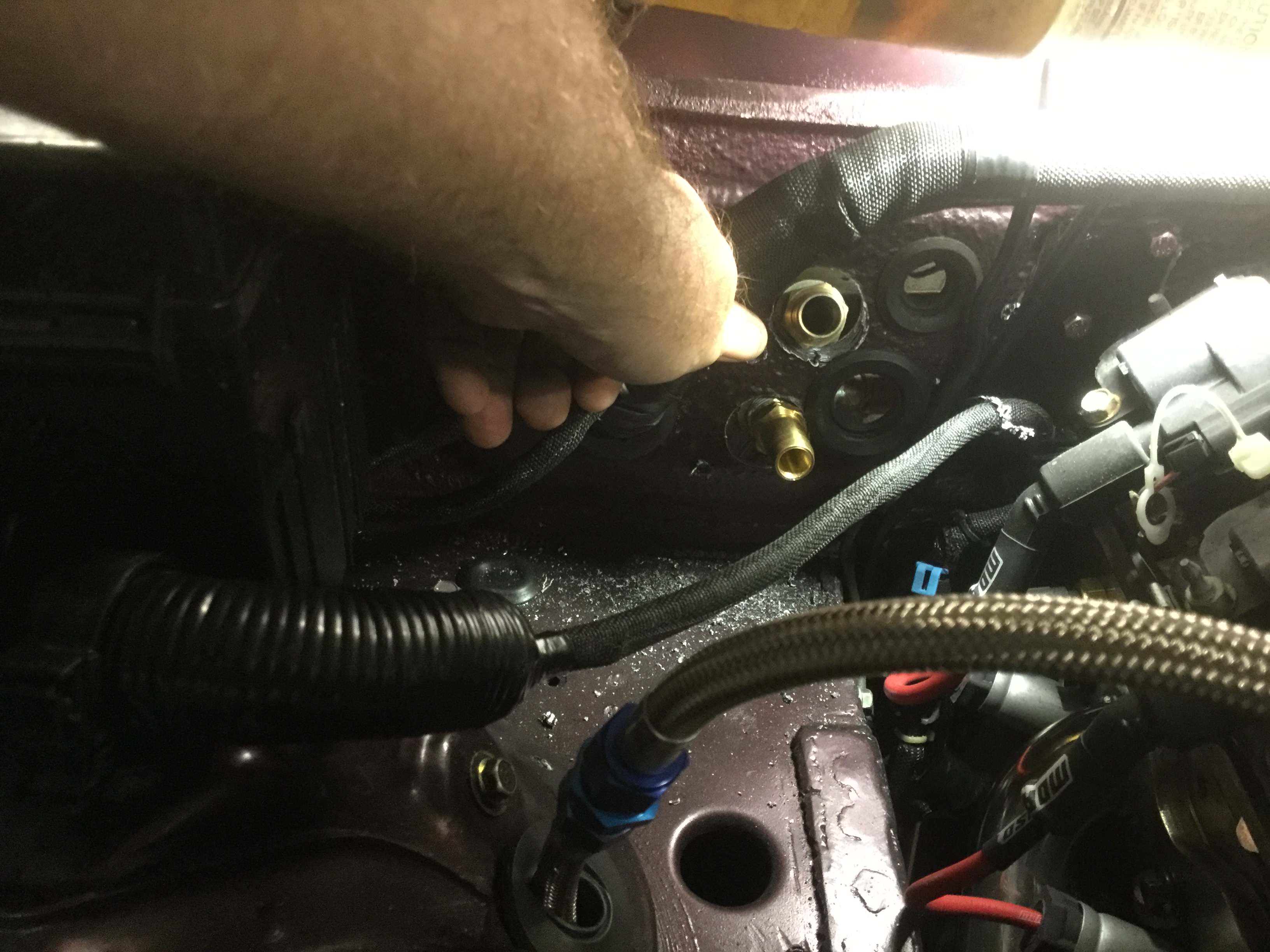
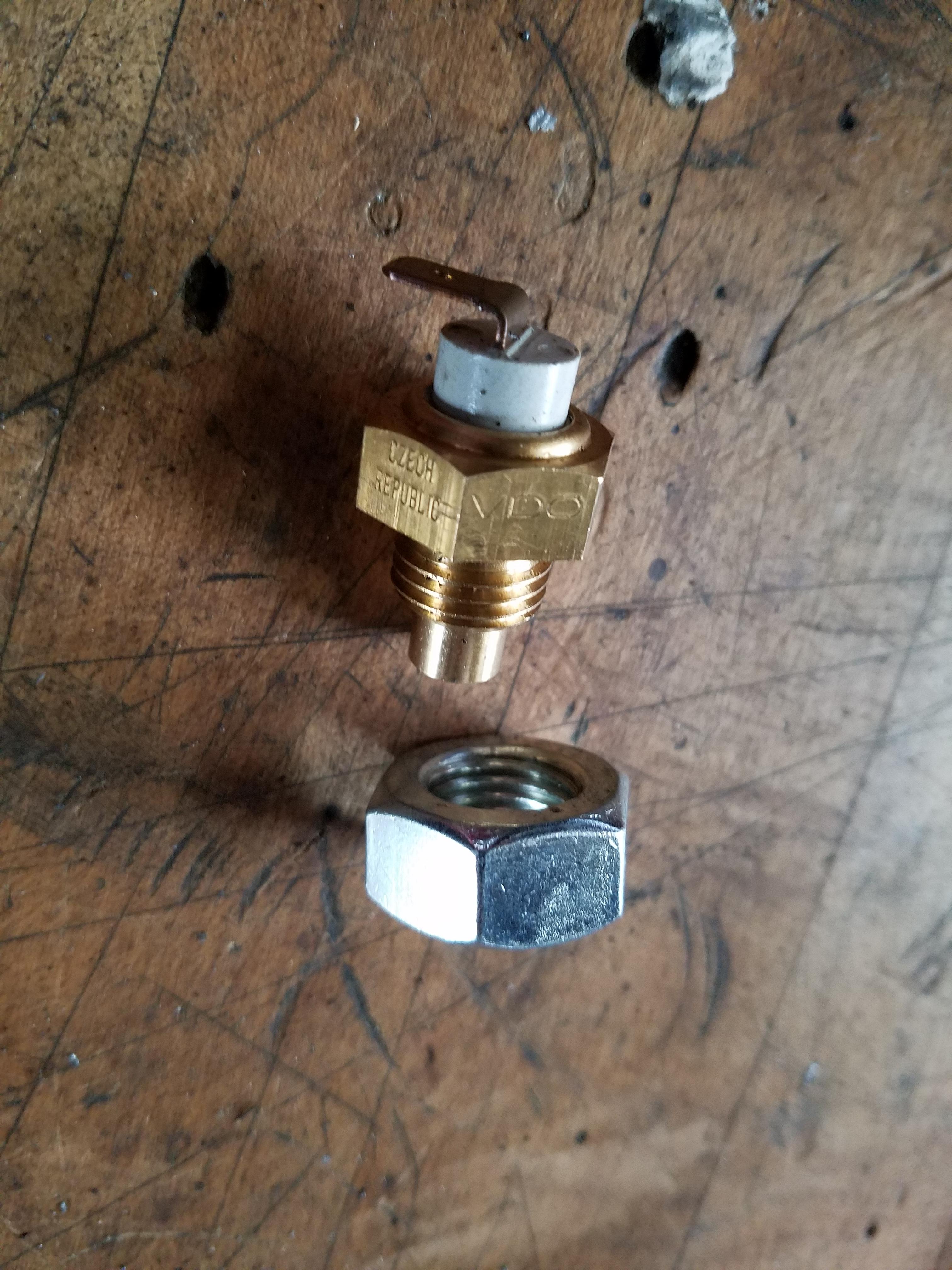
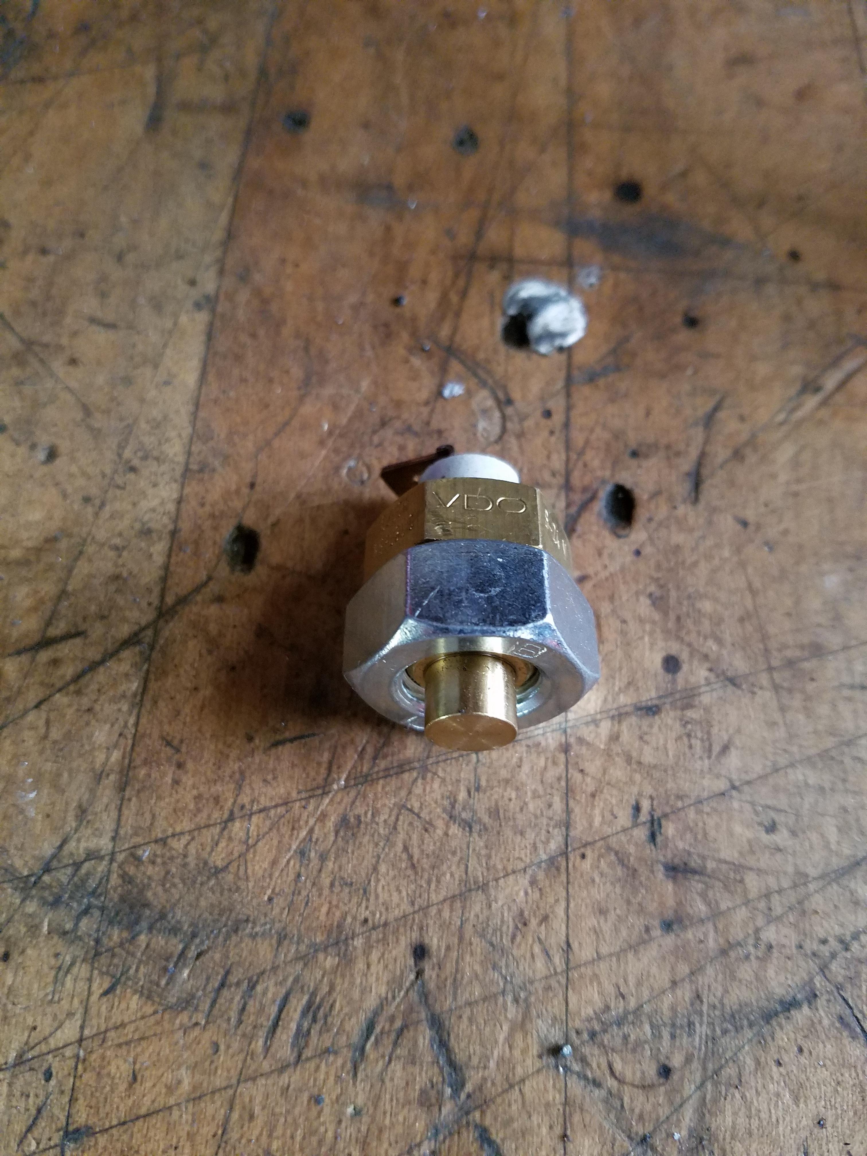
This is the oil temp sensor I used on the Miata before the swap, it threaded nicely into the oil pan drain plug. That won't work on the LS oil pan so I bought a matching nut and will weld it onto the pan as a bung. Should work nicely
Thread Starter
V8 Miata Enthusiast
Joined: Apr 2016
Posts: 412
Likes: 30
From: Tulsa OK
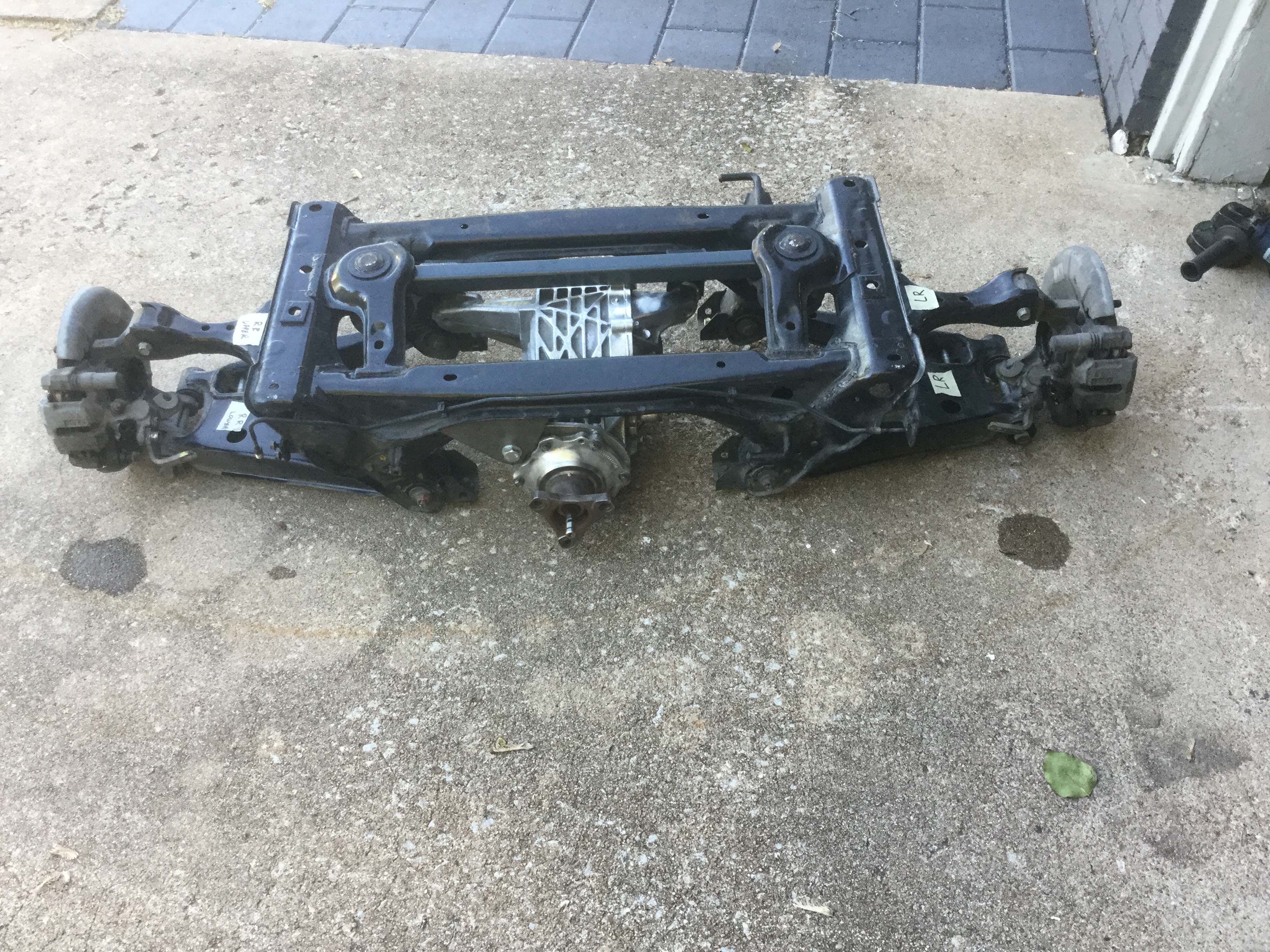
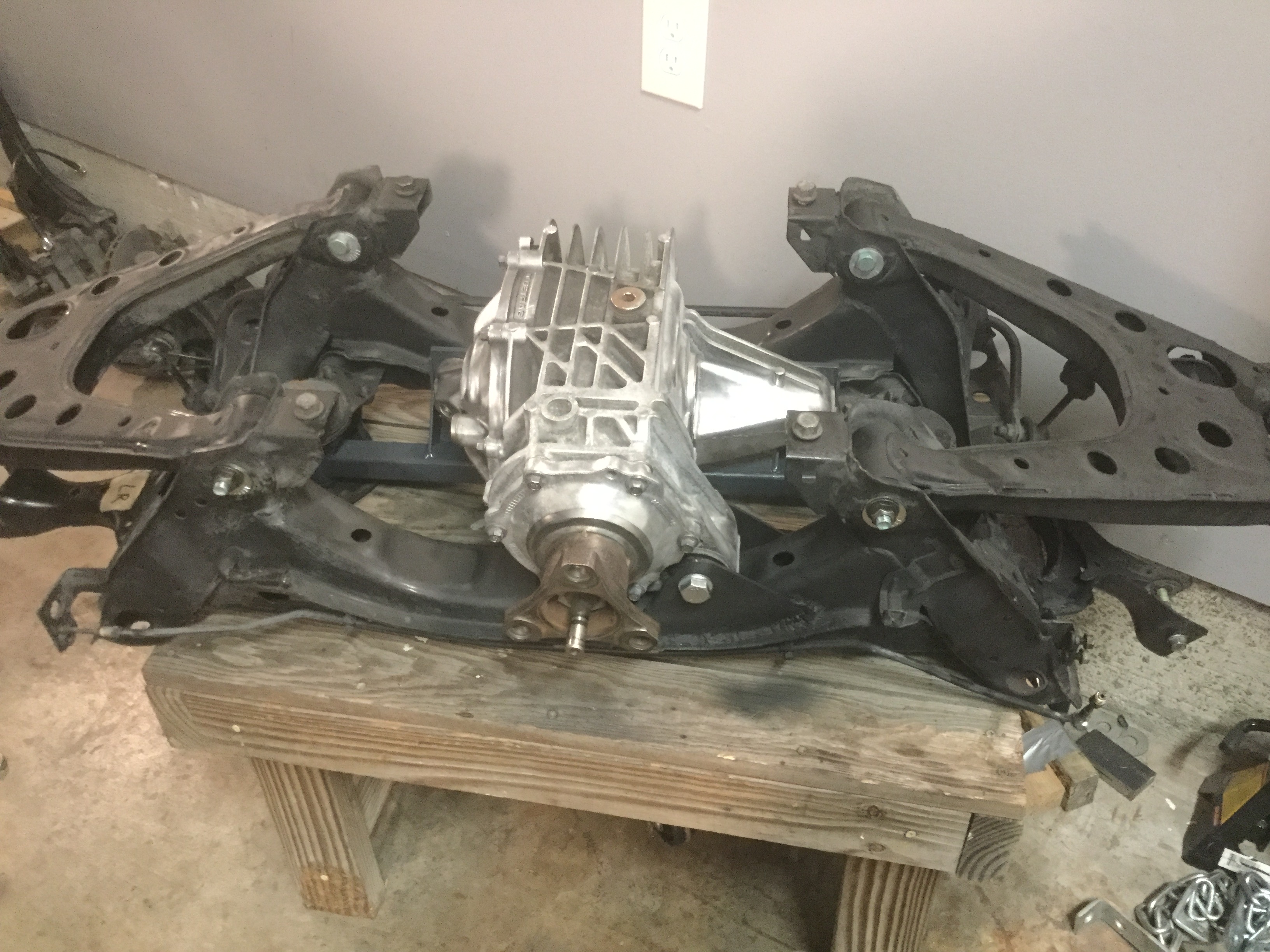
Still working on small things while waiting for the V8 Roadster front subframe.
Pulled off the factory front subframe and removed the components that will be re-used.
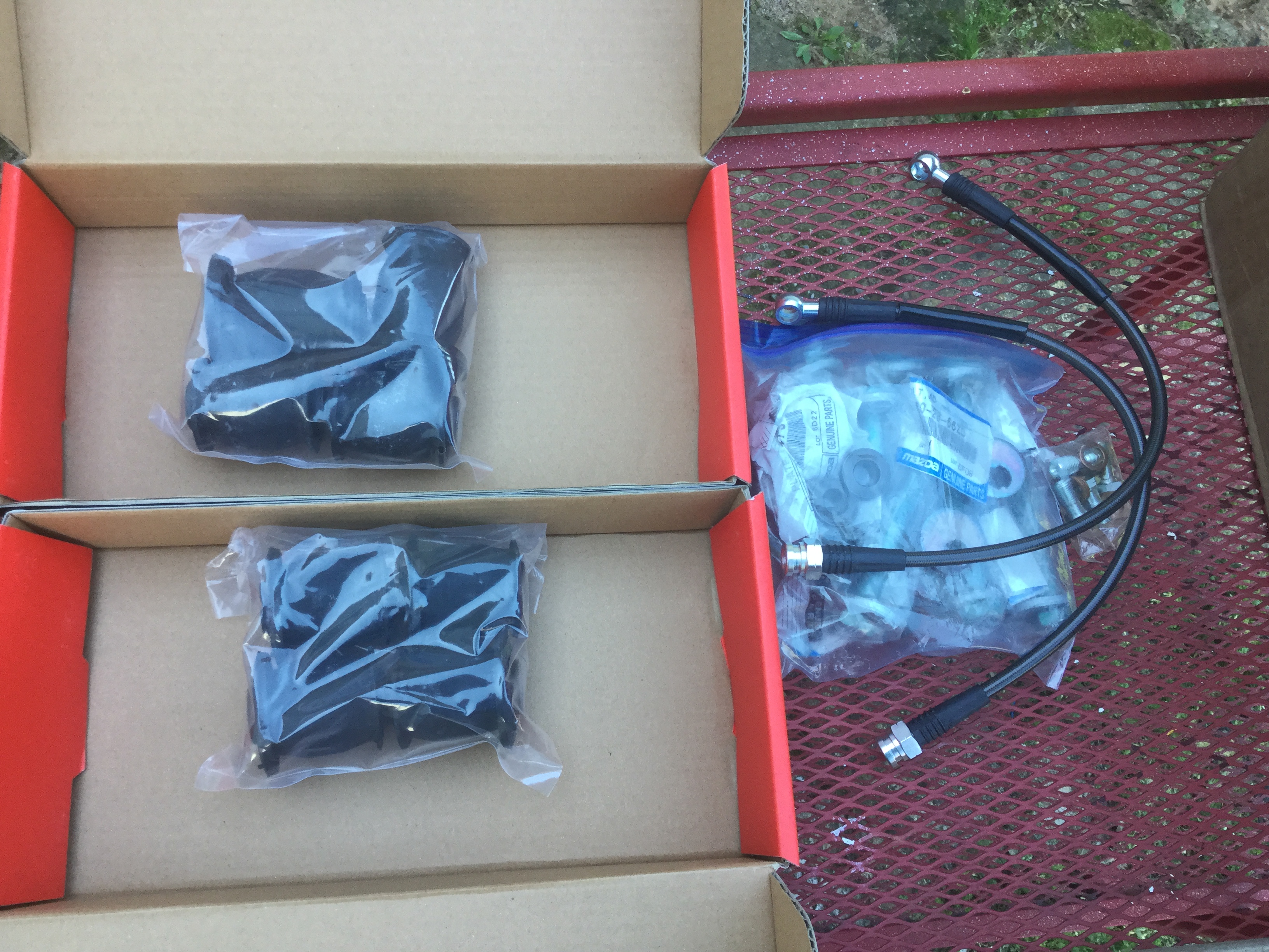
Going with new braided brake lines and new Flyin Miata bushings for the front and rear control arms. Working on the front first.
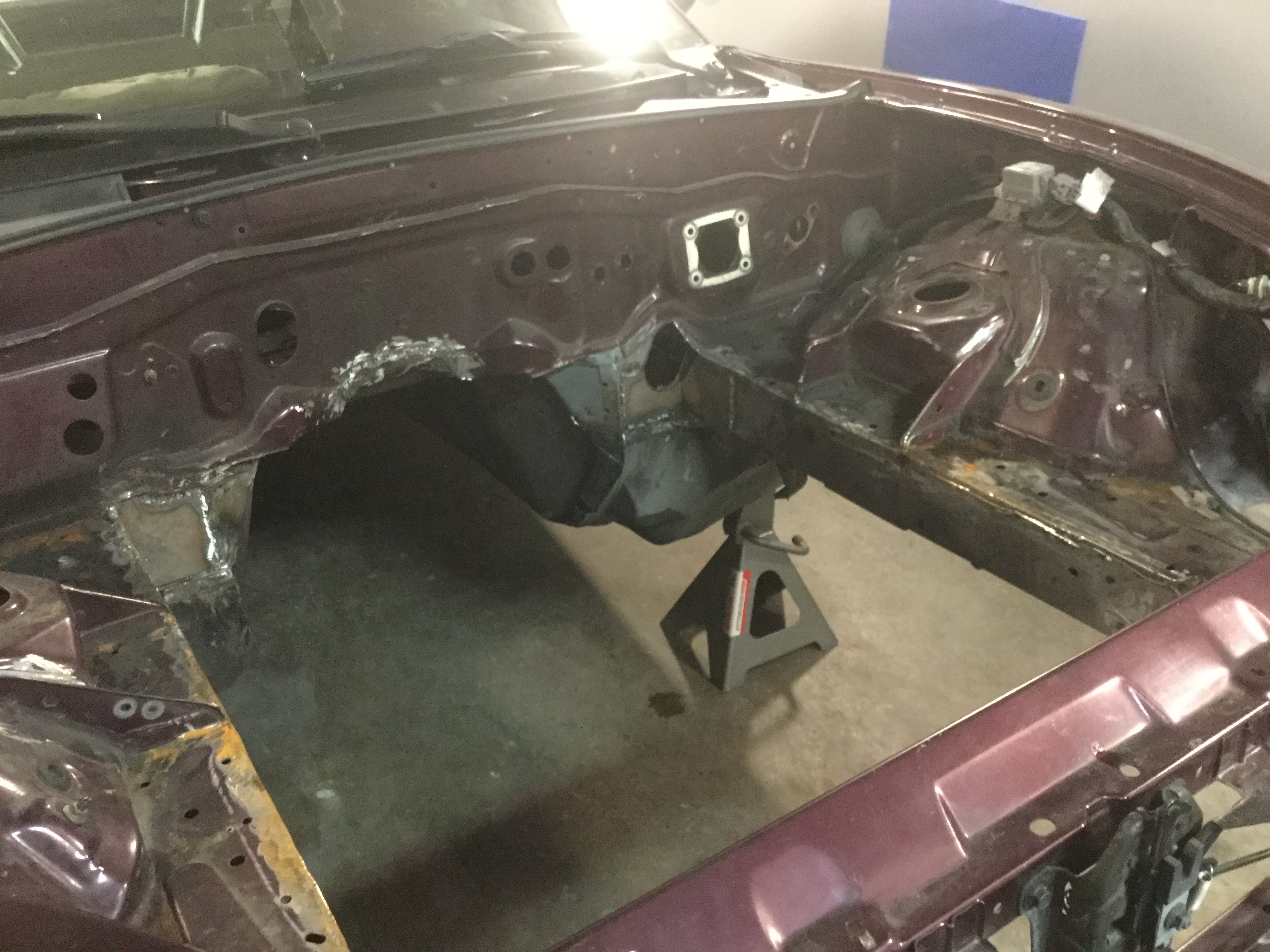
The other thing I will be doing is to do a preliminary engine placement to check the firewall massaging in order to make things go smoother once I do the final fit and massage after the new subframe gets here. The wooden spacers are intended to keep the engine centered in the bay. Didn't take a picture but I also used wood spacers to keep the transmission centered and the shifter in the correct location. Hopefully it is close enough to the final location that no further beating is required. It will be nice to get the engine fit because almost everything else is on hold till that happens.
You can see where the cutting and welding to square up the frame rails cleaned up nicely. As part of the final welding there will be some fabricated angles placed over the corner weld so that everything gets stiffened even further. Don't need any cracking of the frame rail down the road. I will try to get some close up pictures of that gusseting because I have not seen where any other build threads are doing this modification and I feel it gains some valuable real estate and looks much cleaner for the final install.
Pulled off the factory front subframe and removed the components that will be re-used.
Going with new braided brake lines and new Flyin Miata bushings for the front and rear control arms. Working on the front first.
The other thing I will be doing is to do a preliminary engine placement to check the firewall massaging in order to make things go smoother once I do the final fit and massage after the new subframe gets here. The wooden spacers are intended to keep the engine centered in the bay. Didn't take a picture but I also used wood spacers to keep the transmission centered and the shifter in the correct location. Hopefully it is close enough to the final location that no further beating is required. It will be nice to get the engine fit because almost everything else is on hold till that happens.
You can see where the cutting and welding to square up the frame rails cleaned up nicely. As part of the final welding there will be some fabricated angles placed over the corner weld so that everything gets stiffened even further. Don't need any cracking of the frame rail down the road. I will try to get some close up pictures of that gusseting because I have not seen where any other build threads are doing this modification and I feel it gains some valuable real estate and looks much cleaner for the final install.

Thread Starter
V8 Miata Enthusiast
Joined: Apr 2016
Posts: 412
Likes: 30
From: Tulsa OK
Absolutely, you are correct Steve.
I got interrupted in the middle of my previous post due to a family emergency.
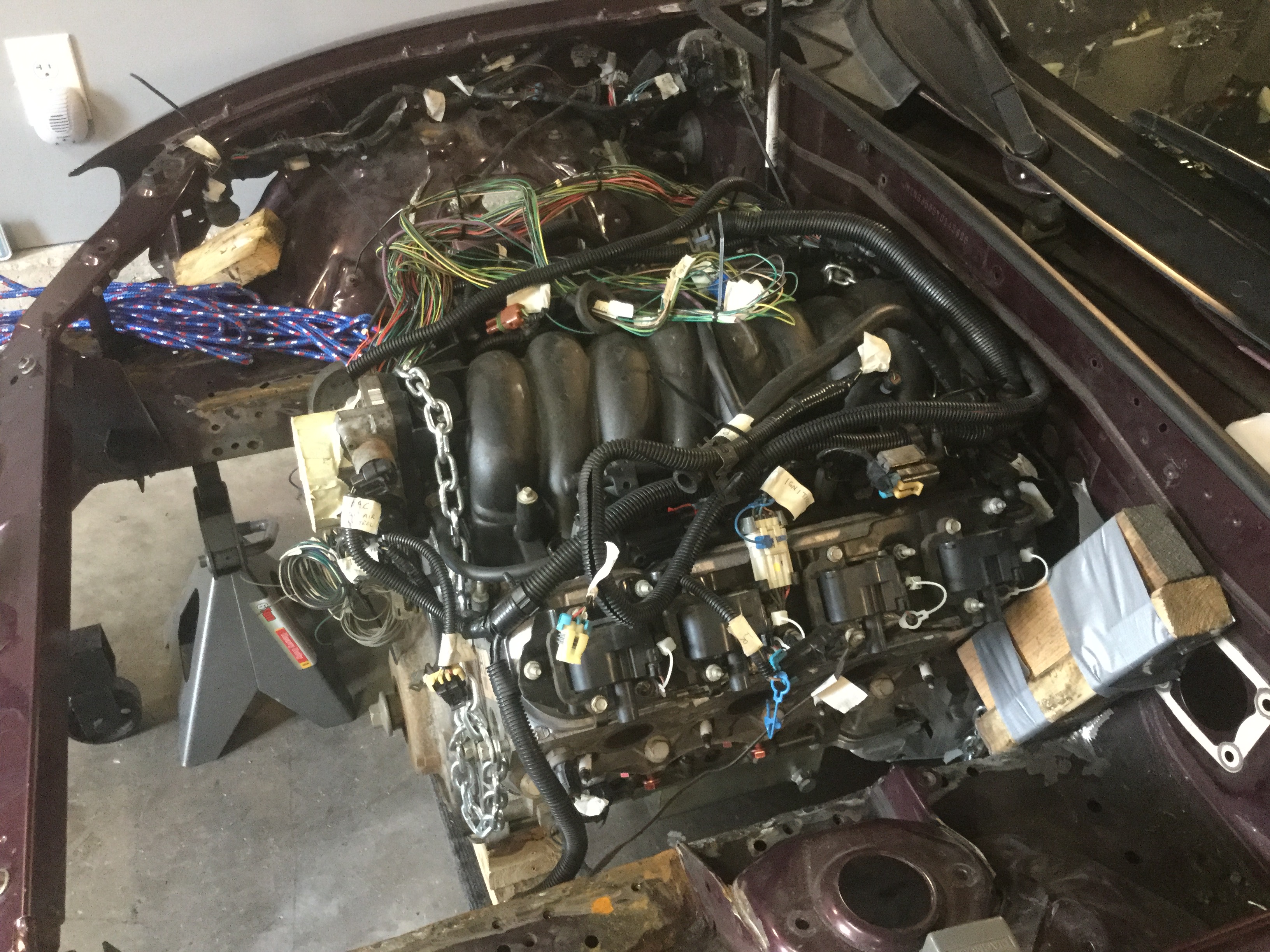
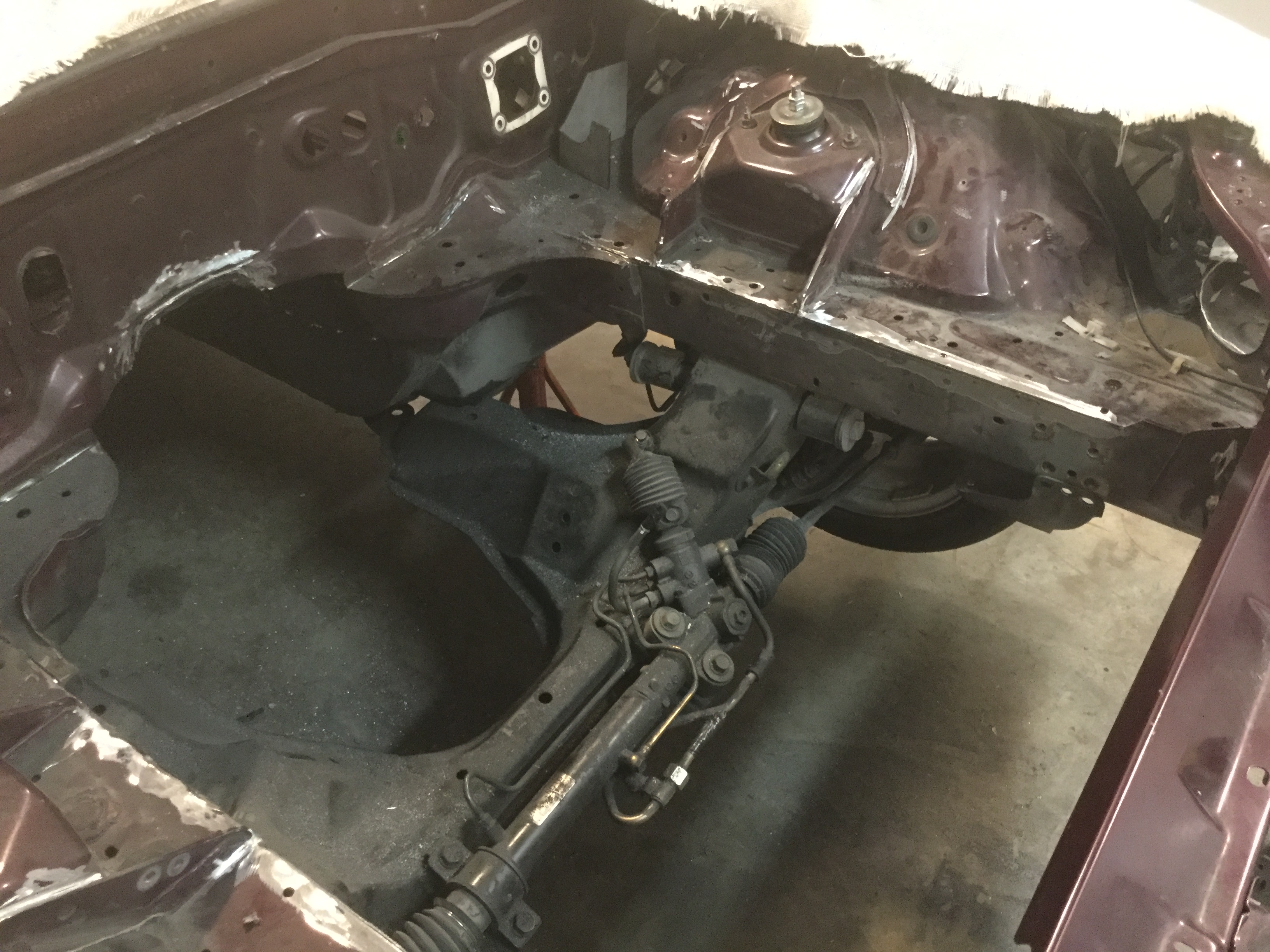
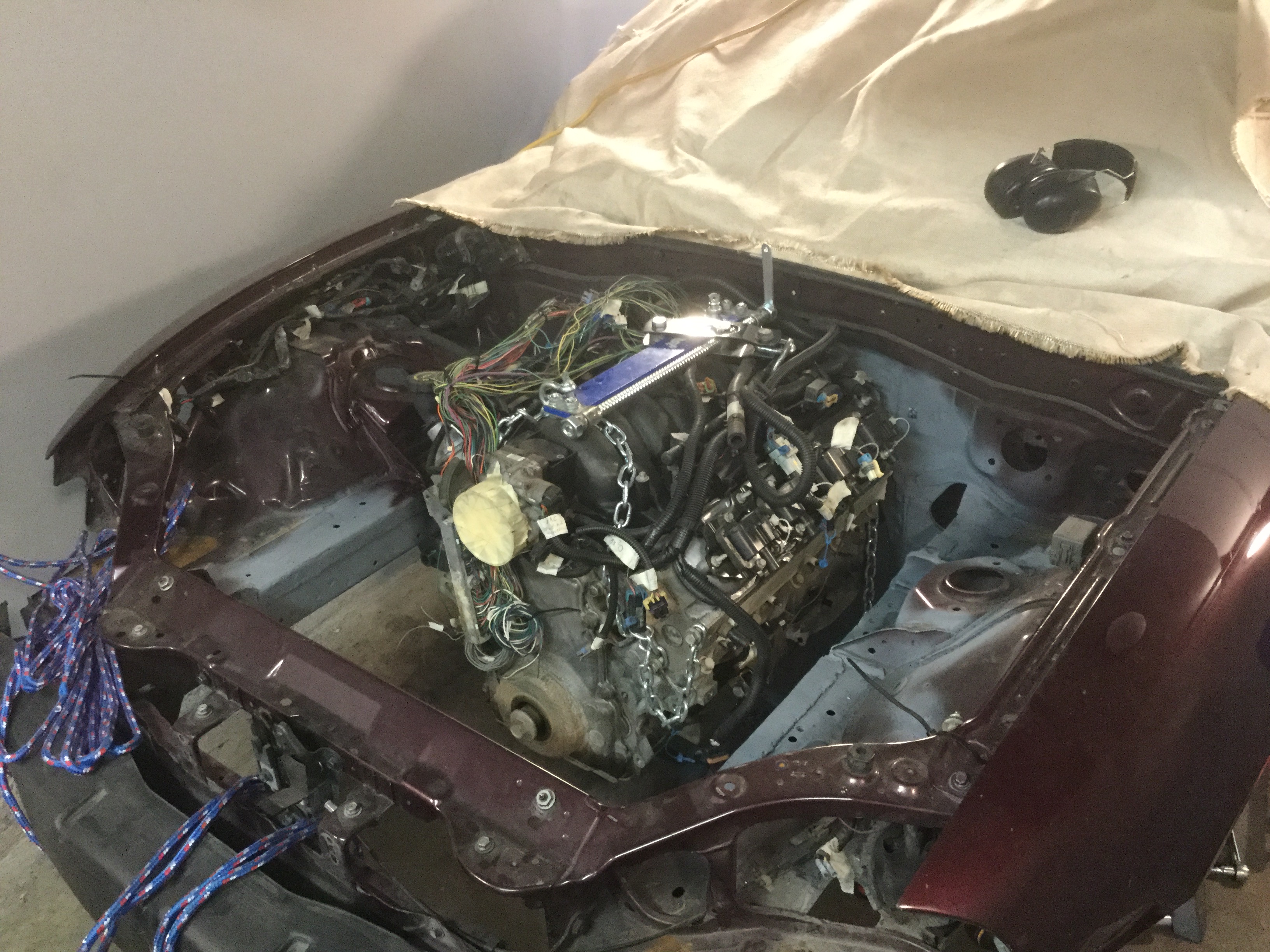
To test fit the engine I raised the body then slid the engine and transmission (on a moving dolly) under the engine bay, positioned it where I expect the subframe will put it, the lowered the body back down and held it in place with wooden spacers.
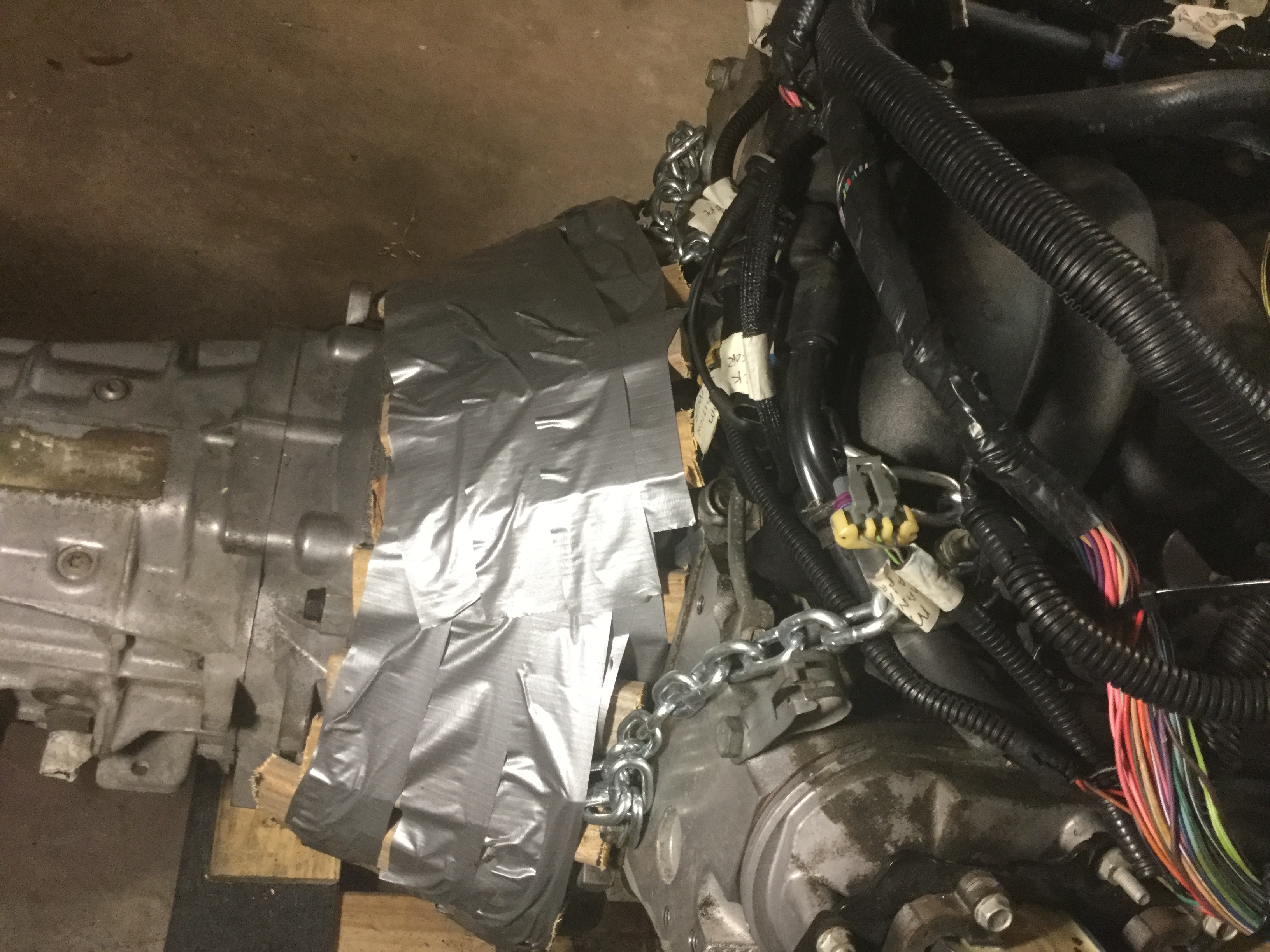
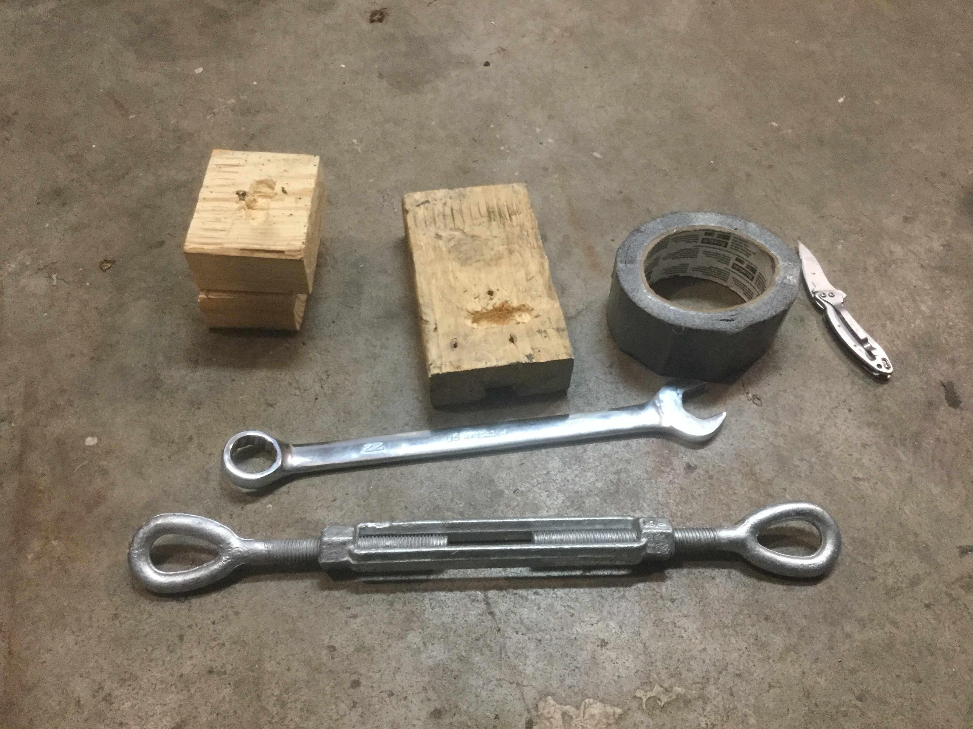
I also cut some 1 x 2 x 7" lg. pieces of lumber to act as spacers between the bellhousing and transmission tunnel and attached them to the bellhousing with duct tape. In theory this should give me 1" minimum spacing between the enlarged area of the tunnel and the drivetrain.
Next, I went into the passenger compartment and whalloped the sheet metal to fit closely.
Once the front subframe shows up I can fit it again with the subframe bolted into the final position. Should happen in the next 2 or 3 days as FedEx says the subframe is in transit.
Update,
Received the necessary parts to get the tunnel changes made.
As noted on the picture above, wood spacers were duct taped onto the bellhousing to give something to fit the tunnel against. The engine / transmission were installed into the car using the V8 Roadster hardware and I tried using a hammer to beat the sheet metal up against the spacers. Doesn't work by simply beating because the sheet metal flexes and bends away from the wood.
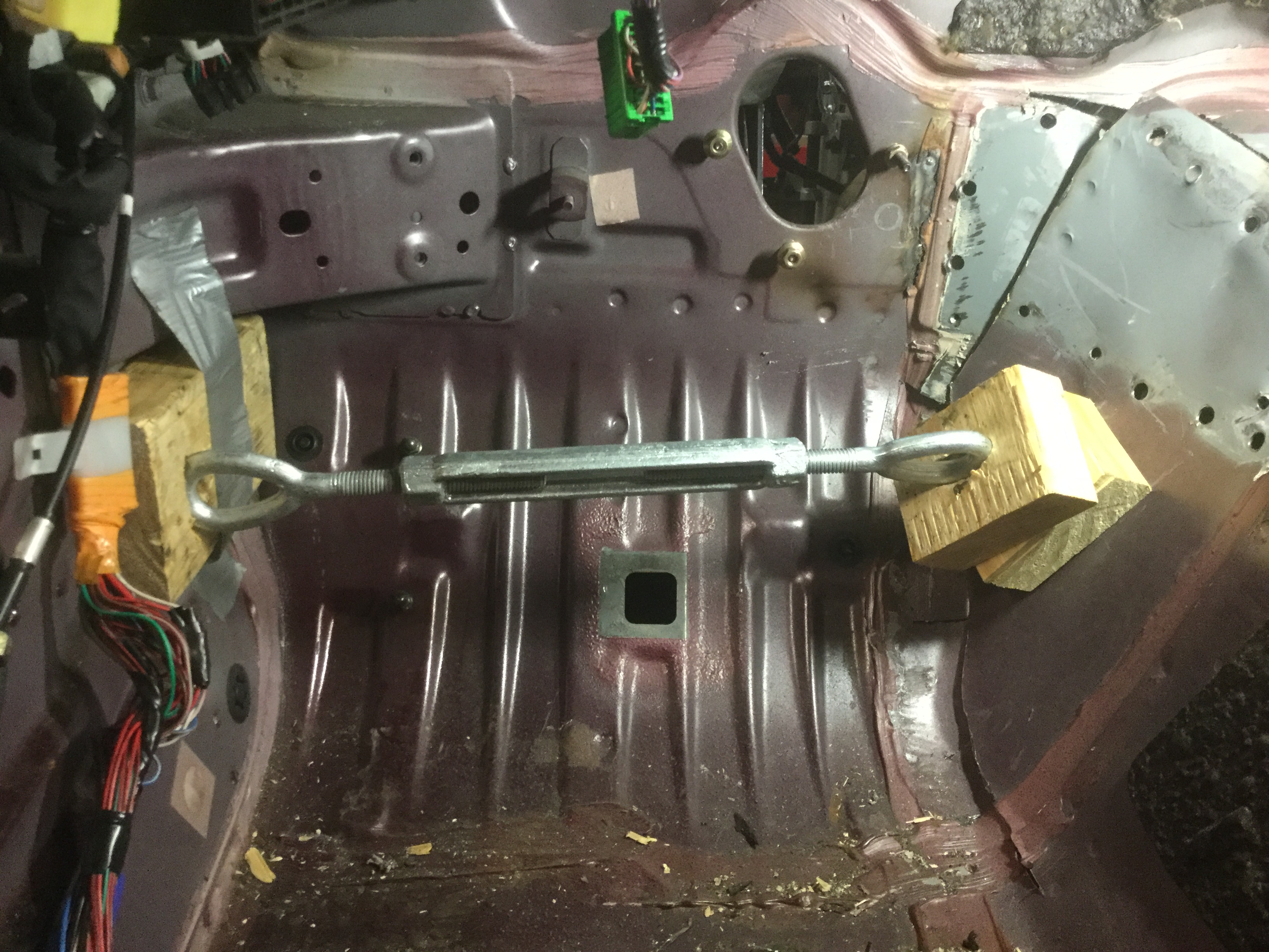
After some study and head scratching I made up a little piece to press the sheet metal into position and hold it long enough to tack weld the pieces together.

It works real good. The tunnel sheet metal gets pressed and held in place long enough to tack weld the metal together. The drive train is in place the entire time so that the fit is just right with no need to beat the tunnel after the fact. It also will (hopefully) allow me to shape the tunnel with just one engine / transmission test fit. Much better than beating and pushing by hand and having the engine in and out several times. It took me about 2 hours to get the left side tacked solidly into the proper shape. Should take about the same time for the right side tunnel so I should have it ready for final welding and sealing up in the next couple of evenings. I will have to remove the engine and transmission in order to do the final welding but in and out twice before being ready for the final paint and sealer is not too bad. Some installs mention being in and out 5 or 6 times.
I got interrupted in the middle of my previous post due to a family emergency.
To test fit the engine I raised the body then slid the engine and transmission (on a moving dolly) under the engine bay, positioned it where I expect the subframe will put it, the lowered the body back down and held it in place with wooden spacers.
I also cut some 1 x 2 x 7" lg. pieces of lumber to act as spacers between the bellhousing and transmission tunnel and attached them to the bellhousing with duct tape. In theory this should give me 1" minimum spacing between the enlarged area of the tunnel and the drivetrain.
Next, I went into the passenger compartment and whalloped the sheet metal to fit closely.
Once the front subframe shows up I can fit it again with the subframe bolted into the final position. Should happen in the next 2 or 3 days as FedEx says the subframe is in transit.
Update,
Received the necessary parts to get the tunnel changes made.
As noted on the picture above, wood spacers were duct taped onto the bellhousing to give something to fit the tunnel against. The engine / transmission were installed into the car using the V8 Roadster hardware and I tried using a hammer to beat the sheet metal up against the spacers. Doesn't work by simply beating because the sheet metal flexes and bends away from the wood.
After some study and head scratching I made up a little piece to press the sheet metal into position and hold it long enough to tack weld the pieces together.
It works real good. The tunnel sheet metal gets pressed and held in place long enough to tack weld the metal together. The drive train is in place the entire time so that the fit is just right with no need to beat the tunnel after the fact. It also will (hopefully) allow me to shape the tunnel with just one engine / transmission test fit. Much better than beating and pushing by hand and having the engine in and out several times. It took me about 2 hours to get the left side tacked solidly into the proper shape. Should take about the same time for the right side tunnel so I should have it ready for final welding and sealing up in the next couple of evenings. I will have to remove the engine and transmission in order to do the final welding but in and out twice before being ready for the final paint and sealer is not too bad. Some installs mention being in and out 5 or 6 times.
Last edited by BGordon; May 16, 2017 at 11:14 AM.
Thread Starter
V8 Miata Enthusiast
Joined: Apr 2016
Posts: 412
Likes: 30
From: Tulsa OK
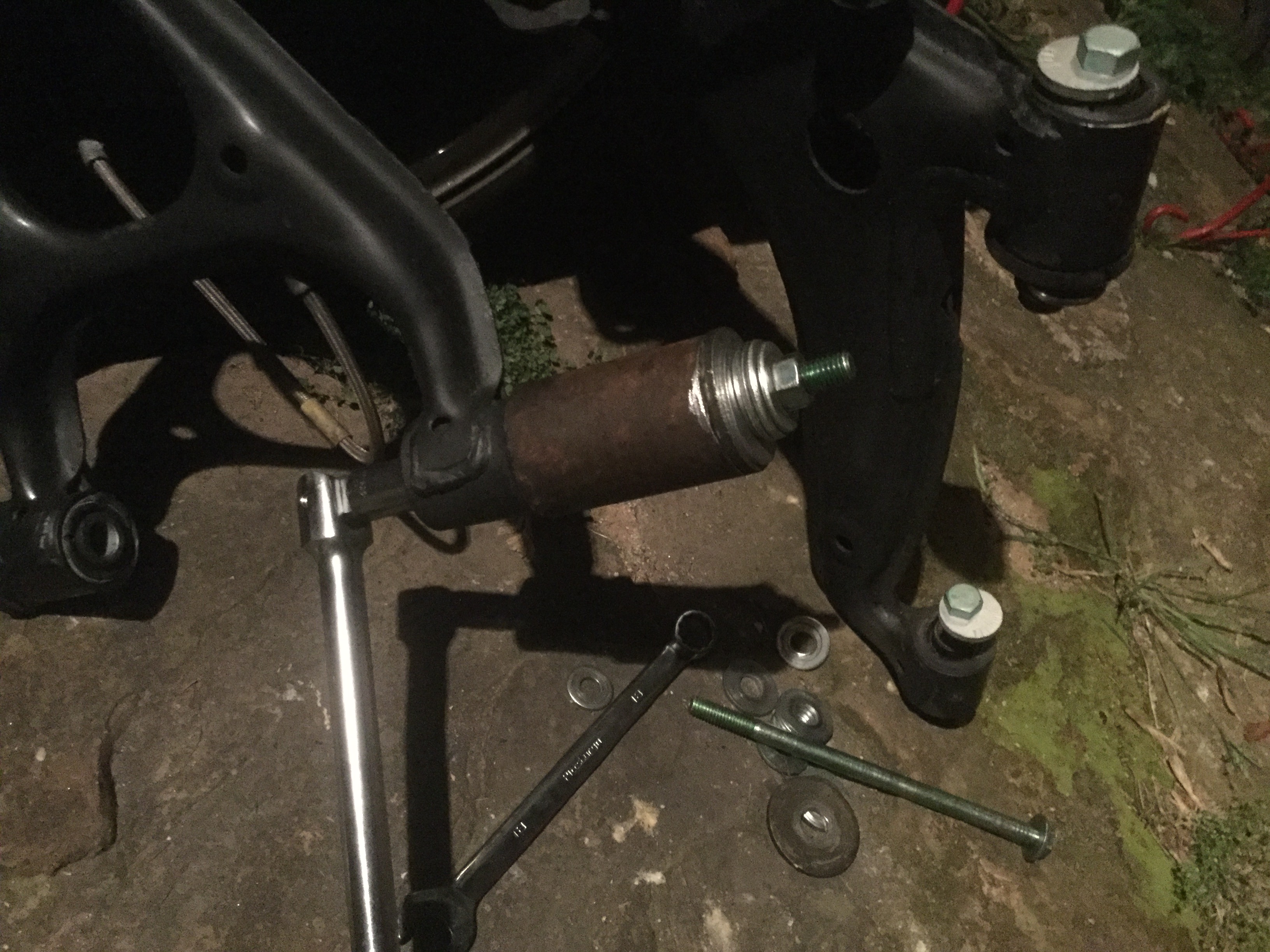
Decided to tackle the front suspension since it was removed along with the subframe for the engine test fit.
Installed new rubber bushings from Flyin Miata. They are harder than the factory rubber but should not squeak like the real hard high performance stuff. A good compromise.
Used the collar and bolt method to pull the old bushings out and push in the new bushings. Also got factory Miata suspension bolts from Flyin Miata. Replaced the brake lines with new braided steel lines while everything is easy to get at.
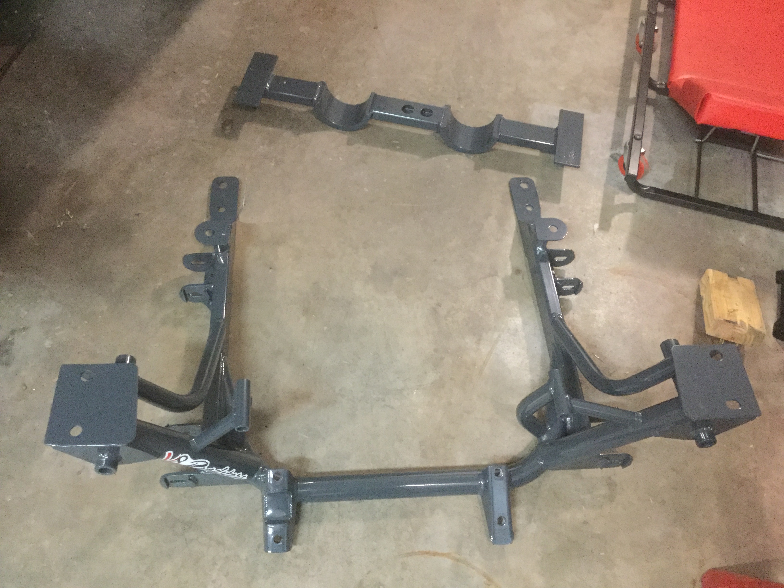
Two packages are scheduled from V8 Roadsters that should contain the front subframe, transmission cross member pieces, the chassis stiffeners that run the length of the chassis underneath the passenger compartment, and the rear differential install kit.
The first package showed up, and in accordance with Murphy's Law it was the actual front subframe and cross member but the installation pieces must be in the second box that has not shipped yet. Not what I was hoping for but at least I have a pretty subframe to look at while waiting. Tomorrow I will probably test fit the subframe to my chassis to make sure it bolts up with no issues. Since I have the extra time, the best thing is to make sure everything is fitting properly.
Installed new rubber bushings from Flyin Miata. They are harder than the factory rubber but should not squeak like the real hard high performance stuff. A good compromise.
Used the collar and bolt method to pull the old bushings out and push in the new bushings. Also got factory Miata suspension bolts from Flyin Miata. Replaced the brake lines with new braided steel lines while everything is easy to get at.
Two packages are scheduled from V8 Roadsters that should contain the front subframe, transmission cross member pieces, the chassis stiffeners that run the length of the chassis underneath the passenger compartment, and the rear differential install kit.
The first package showed up, and in accordance with Murphy's Law it was the actual front subframe and cross member but the installation pieces must be in the second box that has not shipped yet. Not what I was hoping for but at least I have a pretty subframe to look at while waiting. Tomorrow I will probably test fit the subframe to my chassis to make sure it bolts up with no issues. Since I have the extra time, the best thing is to make sure everything is fitting properly.
Thread Starter
V8 Miata Enthusiast
Joined: Apr 2016
Posts: 412
Likes: 30
From: Tulsa OK
Finally making more progress.
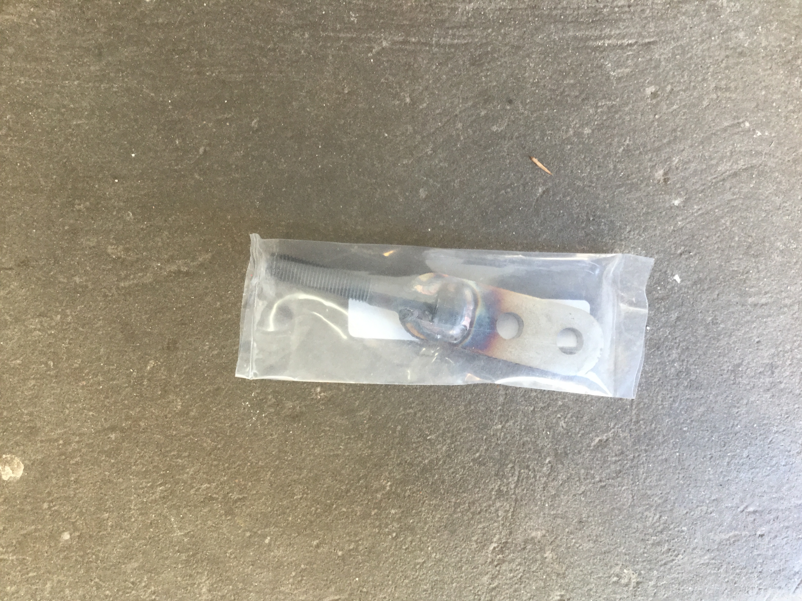
First, I decided to order a Flyin Miata shift handle that bolts to the T56 and threads on the factory Miata Shifter. $40 seems pretty steep for an allen head bolt welded to a small piece of plate. Could have made it myself for about $2
Next, several shipments finally showed up over two days. The biggest is the rest of the V8 Roadster kit to allow me to install the engine & transmission and differential into the Miata. This gives me plenty to work on. Since I have the various rear end parts lined up I decided to focus on that first.
Installed all of the new Flyin Miata rubber bushings so the suspension should be in top shape. The bushings that were removed looked to be fairly new so my guess is the person who owned it two years ago switched out all the bushings. If I was sure they were the harder rubber I would have just left them in and saved myself a day of work but since I have no way to know for sure out came the old and in went the new. If anybody wants the old rubber bushings and adjustment bolts let me know.
After that I welded in the new differential support bracket. It took a call to Flyin Miata since their instructions say to install the bracket at 3" from the support ledge to the center of the bolting hole while the V8 Roadster instructions say to install the bracket so that the differential points 1.5 degrees up from horizontal in the installed position. I went ahead and checked it as I was installing the bracket and in my case the 3" did equal the 1.5 degrees.
Tomorrow I should be able to mount the rear subframe into the car for the last time and then install the differential and axles.
Edit: After further consideration, I decided to leave the rear end out till after spraying the lizard skin insulation.
Oh yes, one last thing for today.
I decided to order the Painless Wiring harness for the LS1 installation that has an extra 48" of wire for mounting the ECU (Part no. 60905)
My hope is to be able to install the ECU either under the passenger seat or behind the passenger seat. Guess we will see.
Last edited by BGordon; May 16, 2017 at 10:49 AM.

V8 Miata Fanatic

Joined: Oct 2012
Posts: 550
Likes: 34
From: Fuquay Varina, NC
You're making some good progress already. Once you drop the LS motor on to the subframe and then test-fit, any areas of concern will show up.
Really enjoy your approach to the heater core plumbing. If I was to do another V8M, I will probably do something similar to yours.
Carry on...
Really enjoy your approach to the heater core plumbing. If I was to do another V8M, I will probably do something similar to yours.
Carry on...
Thread Starter
V8 Miata Enthusiast
Joined: Apr 2016
Posts: 412
Likes: 30
From: Tulsa OK
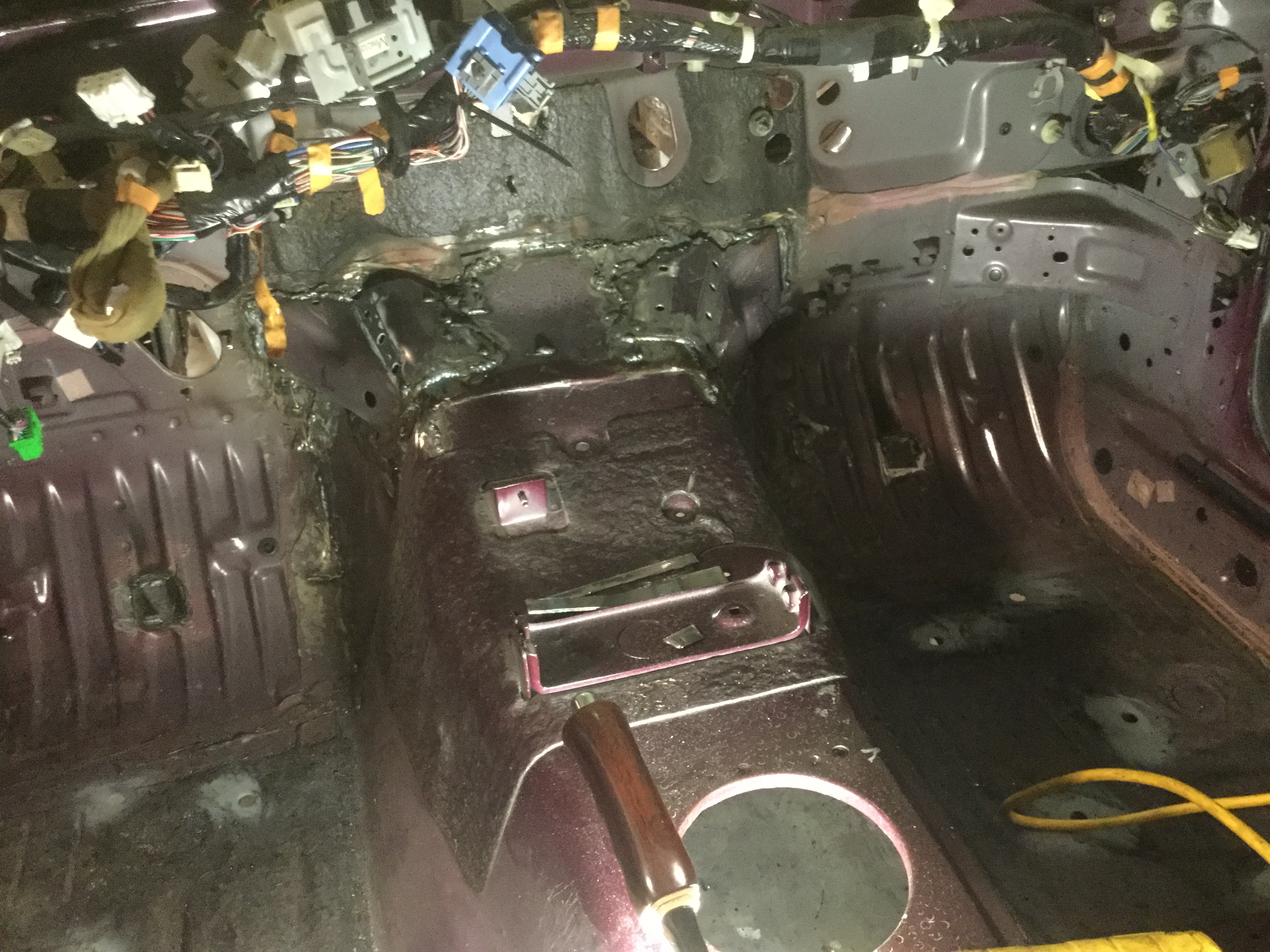
The transmission tunnel shaping went outstanding. In fact, it went well enough that it deserves a more detailed explanation.
I used some pieces of 1 x 2 wood strips tied together with duct tape
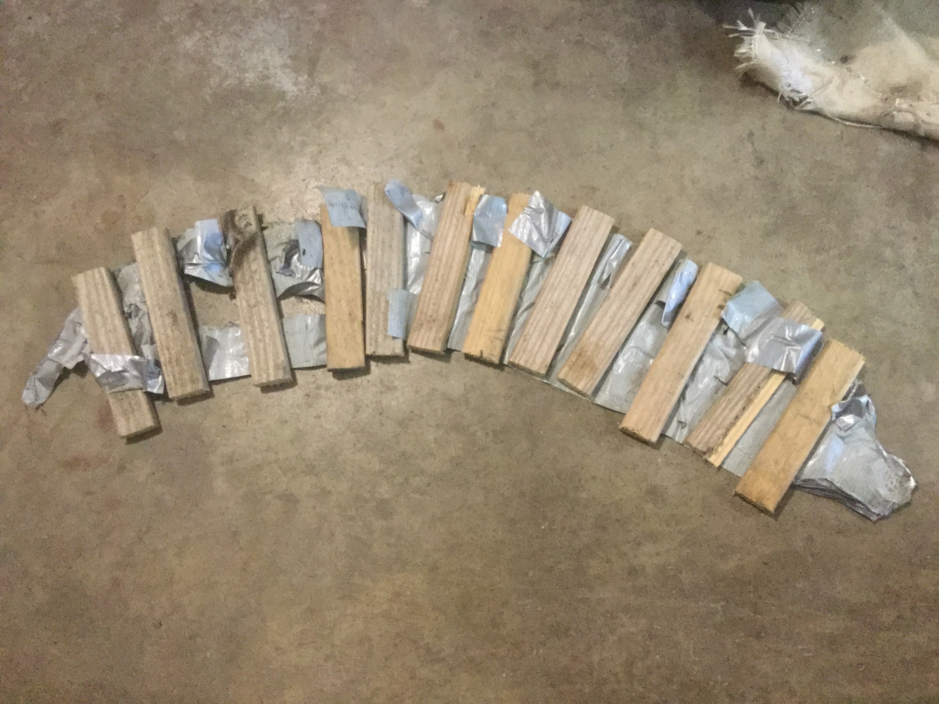
Attached them tot he outside surface of the transmission tunnel to act as spacers between the bellhousing and the tunnel.

Once I received the necessary V8 Roadster pieces to allow test fitting of the drivetrain I made up an adjustable wedge that sits in the footwell and pushes the side of the tunnel against the wooden spacers so that I was able to carefully tackweld the tunnel sheet metal together. The pre-fitting that I had done before the front subframe arrived was actually really close and would probably have done real well but the drivetrain appears to sit a hair towards the passenger side rather than centered between the frame rails.
After tack welding several places inside the passenger compartment I used the wedge to push areas of the tunnel and crawled underneath the car and tacked some places from the under side. After all the tack welding was complete I removed the engine and transmission and beat a place on the passenger side of the firewall where the engine was touching a dimple on the firewall. Welded some places that were not accessible while the drivetrain was installed and removed the wood spacers from the bell housing. Then, I put the drivetrain back in to verify everything fits. Now all I need to do is test install the throttle pedal assembly to make sure it has clearance and test fit the three AC/Heater assemblies that bolt to the firewall. Don't expect any problems but you can never tell.
Edit: The interior stuff test fitted really well. Don't see any interference problems.
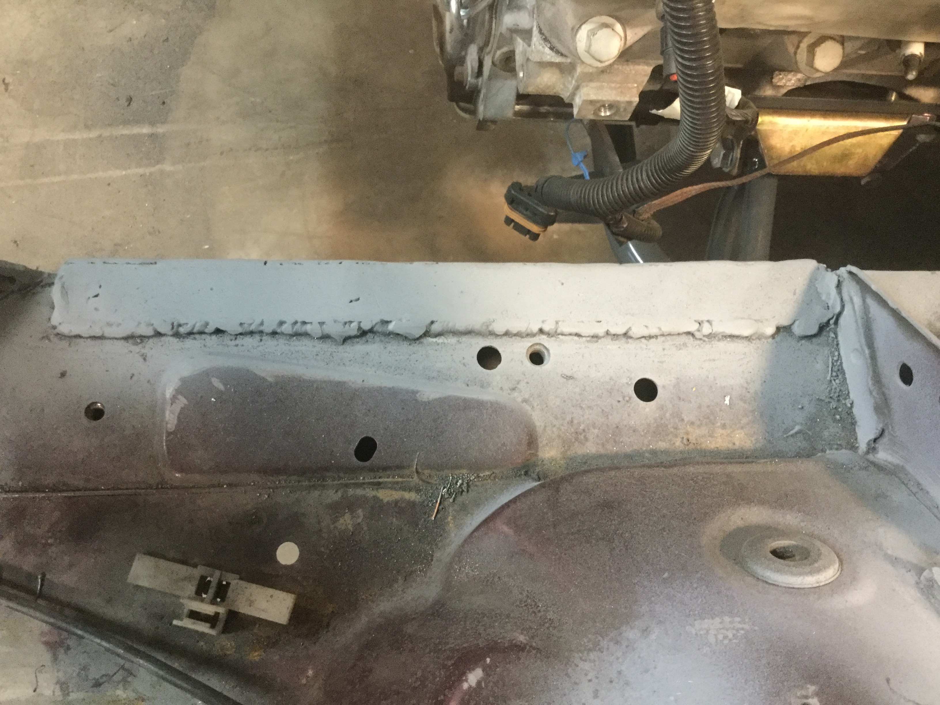
Since that went so well I proceeded with fitting and welding some plate gussets that I am putting into the engine compartment on the frame rails where I removed the pinch plates that were spot welded. I never liked that area on build pictures I have seen as the pinch plates appear to stick out into the area where the headers pass close to the frame rails. Previously I had removed the pinch plates and welded up the corner joint to keep the box frame pieces strong.
After cleaning the paint from the fit-up area I installed some 1/8" x 1" flatbar with plug weld holes drilled along the length to add more strength to the joint.
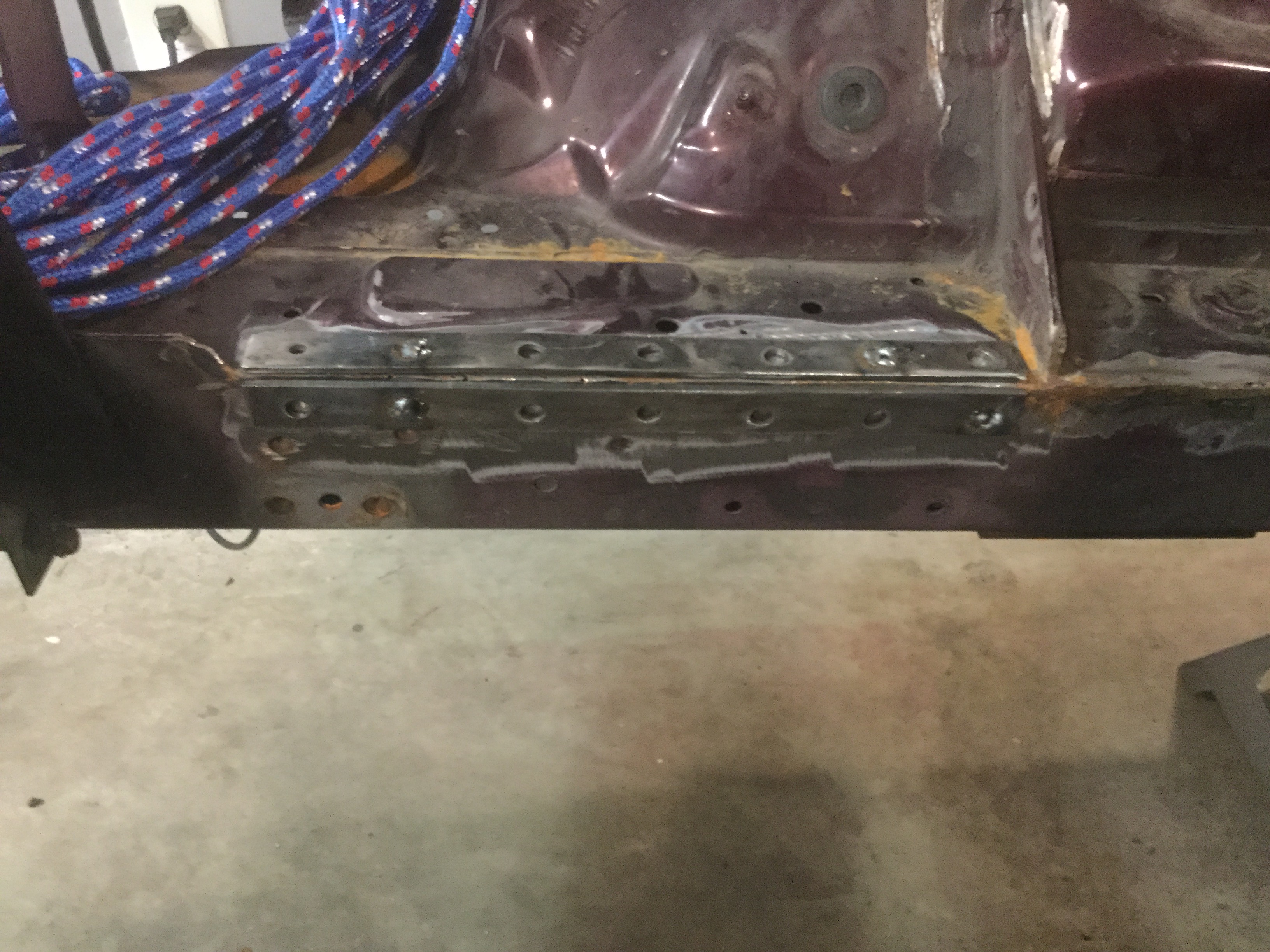
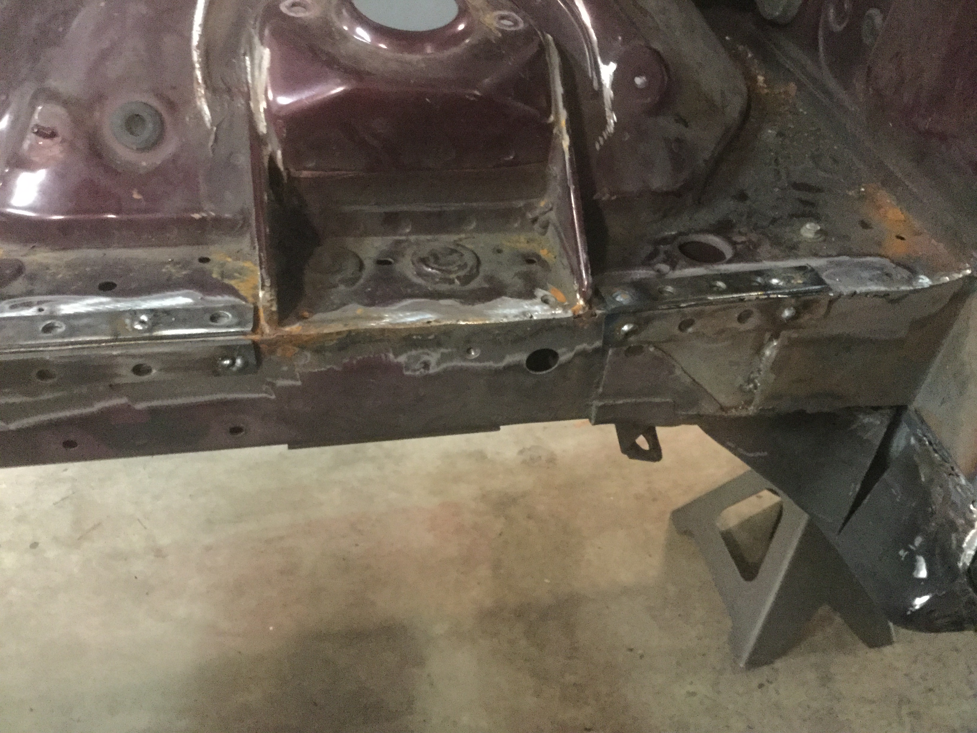
It will take a bit of welding but should strengthen the frame rails and look better than the factory pinch plates. Once the plates are welded in place I will grind down the weld so everything looks nice and clean. After some seam sealer and a coat of paint it should look great.
I used some pieces of 1 x 2 wood strips tied together with duct tape
Attached them tot he outside surface of the transmission tunnel to act as spacers between the bellhousing and the tunnel.
Once I received the necessary V8 Roadster pieces to allow test fitting of the drivetrain I made up an adjustable wedge that sits in the footwell and pushes the side of the tunnel against the wooden spacers so that I was able to carefully tackweld the tunnel sheet metal together. The pre-fitting that I had done before the front subframe arrived was actually really close and would probably have done real well but the drivetrain appears to sit a hair towards the passenger side rather than centered between the frame rails.
After tack welding several places inside the passenger compartment I used the wedge to push areas of the tunnel and crawled underneath the car and tacked some places from the under side. After all the tack welding was complete I removed the engine and transmission and beat a place on the passenger side of the firewall where the engine was touching a dimple on the firewall. Welded some places that were not accessible while the drivetrain was installed and removed the wood spacers from the bell housing. Then, I put the drivetrain back in to verify everything fits. Now all I need to do is test install the throttle pedal assembly to make sure it has clearance and test fit the three AC/Heater assemblies that bolt to the firewall. Don't expect any problems but you can never tell.
Edit: The interior stuff test fitted really well. Don't see any interference problems.
Since that went so well I proceeded with fitting and welding some plate gussets that I am putting into the engine compartment on the frame rails where I removed the pinch plates that were spot welded. I never liked that area on build pictures I have seen as the pinch plates appear to stick out into the area where the headers pass close to the frame rails. Previously I had removed the pinch plates and welded up the corner joint to keep the box frame pieces strong.
After cleaning the paint from the fit-up area I installed some 1/8" x 1" flatbar with plug weld holes drilled along the length to add more strength to the joint.
It will take a bit of welding but should strengthen the frame rails and look better than the factory pinch plates. Once the plates are welded in place I will grind down the weld so everything looks nice and clean. After some seam sealer and a coat of paint it should look great.
Last edited by BGordon; May 16, 2017 at 11:18 AM.
Thread Starter
V8 Miata Enthusiast
Joined: Apr 2016
Posts: 412
Likes: 30
From: Tulsa OK
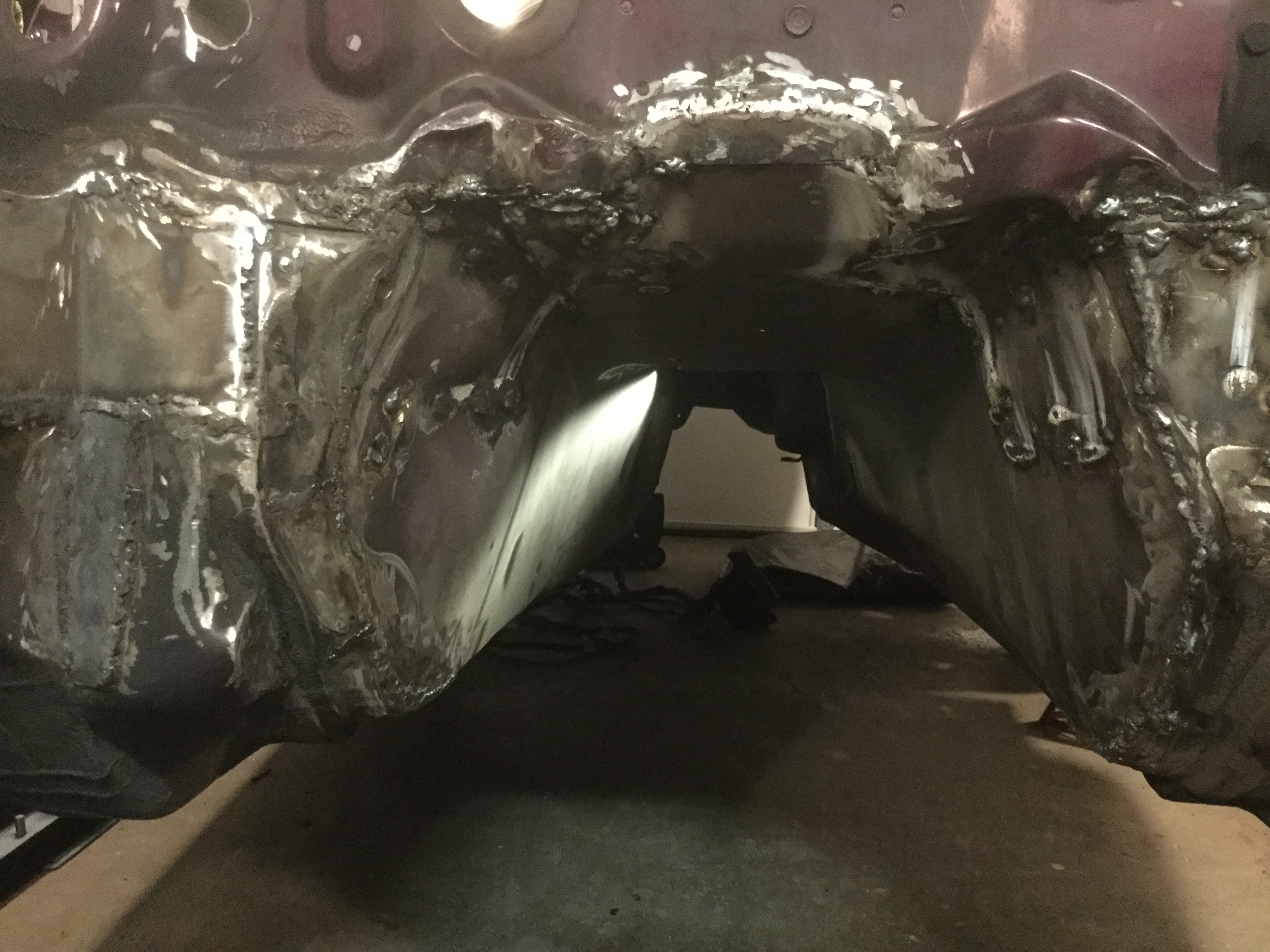
I think I am FINALLY done with the welding in the engine bay and the transmission tunnel.
Went thru 5 pounds of MIG wire.
Unless something even worse comes along, I am going to call that the worst part of the V8 install.
Going to have to do quite a bit of grinding to clean it up because this was my first attempt at welding and it loos like a 6 year old did it in some places. Once it gets cleaned up and covered with seam sealer it should look acceptable.
One thing I figured out as part of the surgery process is that the Flyin Miata instructions dealing with the cut and shape of the tunnel are quite conservative for my car. My guess is that they are probably accurate for an NA. If you are cutting and shaping an NB, the first time around try to make the cuts about half the length of the instructions and test fit. You might have to enlarge it but it might be enough and save you a whole bunch of welding to close up the tunnel.
I did exactly the opposite and figured if the instructions say to make a 5" lg. cut that 8" would be better. Not a smart move in hind sight.
If I get energetic I might just take some measurements at the bell housing and transmission so that somebody could install those two items with the transmission cross member to get a good trial fit. I do know that the engine sits slightly towards the passenger side but the transmission shift handle appears to be really well centered right/left in the opening. Mine sits slightly rearwards and my passenger head touched the firewall forcing me to beat the right firewall back a bit in the area of the cylinder head, which means mine is about 1" further rearwards than some of the other install pictures I have seen.
V8 Miata Prot�g�
Joined: May 2016
Posts: 452
Likes: 25
From: Ambler, PA
One thing to be aware of now is to check for clearance around the throttle pedal. Make sure it has enough range of movement with carpet, etc installed. Easier to modify it now than with dash, console, carpet installed.
Thread Starter
V8 Miata Enthusiast
Joined: Apr 2016
Posts: 412
Likes: 30
From: Tulsa OK
I bolted the pedal assembly in place yesterday evening and had about 1" of clearance to the metal. Is that sufficient?
If it is not enough my answer will probably be to heat and bend the pedal rod because the tunnel is right at 1" away from the bell housing in that location.
My method of using wooden spacers between the bell housing and the tunnel gives me the maximum amount of clearance between the pedal and the tunnel and I was very careful in the specific area where I knew the pedal would be situated.
Edit: The method of shaping the transmission tunnel gave me the most clearance possible and 1" was more than enough to clear everything nicely once the interior and carpet was put back in the car.
Last edited by BGordon; Oct 11, 2017 at 04:25 PM.
Thread Starter
V8 Miata Enthusiast
Joined: Apr 2016
Posts: 412
Likes: 30
From: Tulsa OK
Thanks for the kind words.
My opinion is that the build threads on this website have a progression of improvements and I am trying to help out in that respect.
A year or two down the road somebody will figure out improvements and I will be saying to myself, "You dummy. Why did you not think of doing it that way".
The other thin I feel is important is to highlight the things that are missing or incomplete in the Flyin Miata instructions. The instructions are free and it is really great they put them out there rather than charging people to gain from their experience but there is still room for improvement.
V8 Miata Prot�g�
Joined: May 2016
Posts: 452
Likes: 25
From: Ambler, PA
I bolted the pedal assembly in place yesterday evening and had about 1" of clearance to the metal. Is that sufficient?
If it is not enough my answer will probably be to heat and bend the pedal rod because the tunnel is right at 1" away from the bell housing in that location.
If it is not enough my answer will probably be to heat and bend the pedal rod because the tunnel is right at 1" away from the bell housing in that location.
Thread Starter
V8 Miata Enthusiast
Joined: Apr 2016
Posts: 412
Likes: 30
From: Tulsa OK
Yesterday evening was grinding and more grinding on welds. No fun but had to be done.
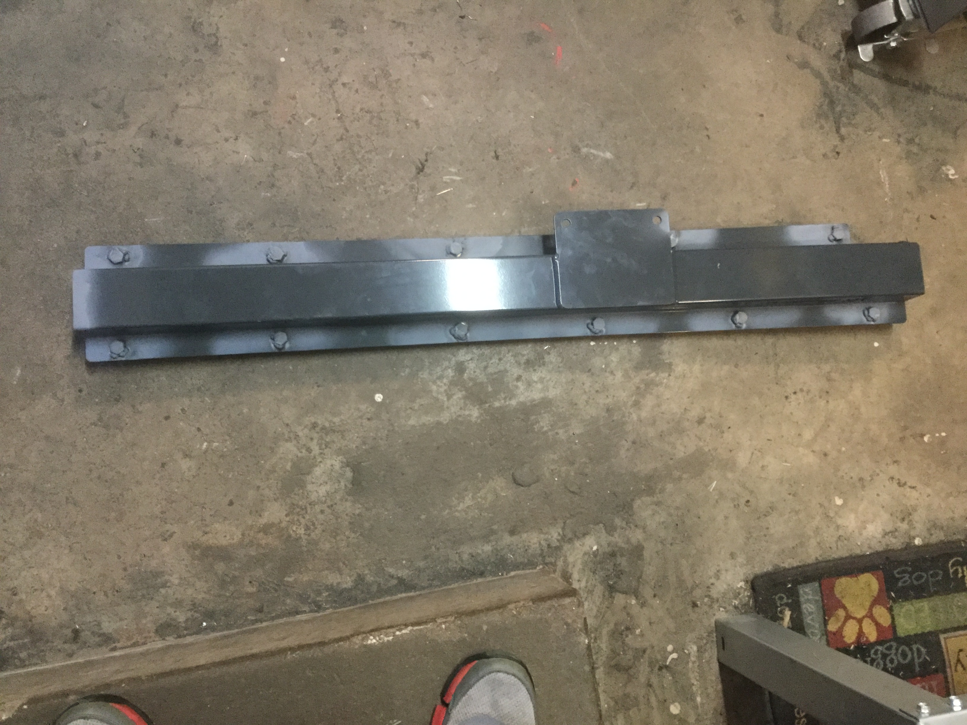
For a short break from grinding I went ahead and installed the frame stiffeners that run from front to back and bolt to the floor of the passenger compartment. I want these braces in place before spraying the insulation on the car so installing them now is the logical step in the assembly process.
My suspicion is that most would install the bolts with the heads inside the passenger compartment and thread the nuts from the under side of the car. I chose to do it the other way for a couple of reasons.
First, by having the bolt head on the underside of the car, the head can be tack welded to the support brace so it will stay firmly in place with no worry about the bolt loosening up and falling out at some point in the future.
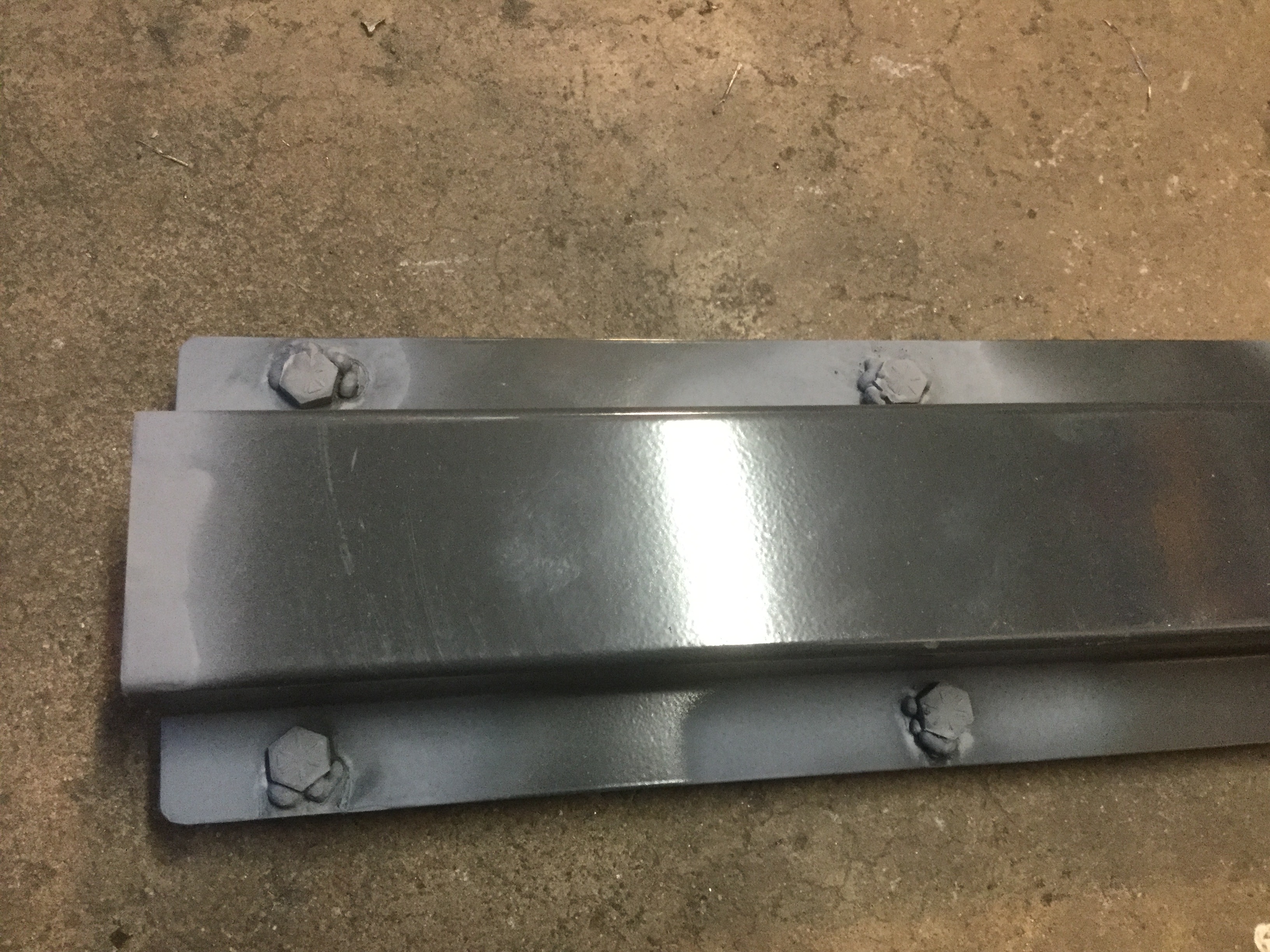
Second, by putting the head outside the car in the elements, there is no worry that the threads could rust in the future. I have seen way too many bolts that have the threads so rusted that the bolt has to be drilled out. Not sure it will ever be a potential problem with this car because it has always been a garage queen and should continue to be one in the future but that is no reason to do things the easy way rather than the right way.
I will take a cut off wheel and nip the excess bolt length off flush with the top of the nut so it will not intrude into the floor any more than having the bolt head installed. The installation kit comes with nuts that have the nylon lock so hopefully the nuts will not back off in the future. Still might tack the nuts to the floor just to make sure.
Once the Lizard Skin insulation is sprayed in place, both the interior and exterior surfaces will be covered so hopefully no moisture can get into the area.
For a short break from grinding I went ahead and installed the frame stiffeners that run from front to back and bolt to the floor of the passenger compartment. I want these braces in place before spraying the insulation on the car so installing them now is the logical step in the assembly process.
My suspicion is that most would install the bolts with the heads inside the passenger compartment and thread the nuts from the under side of the car. I chose to do it the other way for a couple of reasons.
First, by having the bolt head on the underside of the car, the head can be tack welded to the support brace so it will stay firmly in place with no worry about the bolt loosening up and falling out at some point in the future.
Second, by putting the head outside the car in the elements, there is no worry that the threads could rust in the future. I have seen way too many bolts that have the threads so rusted that the bolt has to be drilled out. Not sure it will ever be a potential problem with this car because it has always been a garage queen and should continue to be one in the future but that is no reason to do things the easy way rather than the right way.
I will take a cut off wheel and nip the excess bolt length off flush with the top of the nut so it will not intrude into the floor any more than having the bolt head installed. The installation kit comes with nuts that have the nylon lock so hopefully the nuts will not back off in the future. Still might tack the nuts to the floor just to make sure.
Once the Lizard Skin insulation is sprayed in place, both the interior and exterior surfaces will be covered so hopefully no moisture can get into the area.
V8 Miata Prot�g�
Joined: May 2016
Posts: 452
Likes: 25
From: Ambler, PA
You mentioned being new at welding, and I'm no expert myself. My swap has been a good learning experience. With regard to the welds of your bolts to your frame rails, I'm not sure what welder you are using, but you may want to try turning up the dial on the thickness of metal just by the look of it to get some more heat into it. Or it might be you need to hold the electrode a bit closer to transfer more heat, or maybe the metal wasn't prepped to bare metal. Just some suggestions. 
Thread Starter
V8 Miata Enthusiast
Joined: Apr 2016
Posts: 412
Likes: 30
From: Tulsa OK
You are correct. I had the welder set for doing patch welds to the thin transmission tunnel and used the same settings for tacking on the bolt heads.
They held well enough to tighten down the bracing nuts on the inside of the passenger compartment.
I will take a look this evening and see about setting it a bit hotter and putting in some better weld.
They held well enough to tighten down the bracing nuts on the inside of the passenger compartment.
I will take a look this evening and see about setting it a bit hotter and putting in some better weld.

V8 Miata Follower
Joined: Mar 2016
Posts: 156
Likes: 18
From: Farmington Hills, MI
I would leave them be. If the welds were strong enough to successfully torque them, then they're good. The only reason to weld the head of a bolt is to turn it into a stud, but I'd rather leave it a "cold" weld, and not interrupt the material properties of the bolt. If somehow they are welded with a slight gap in between the bolt head and the frame rail, the load is now being taken up by the weld. If the weld is small enough that it's much less stiff than the bolt itselt, then the bolt head will seat properly to the frame rail and provide the proper clamp load, regardless of weld integrity. Worst case is the weld breaks when trying to remove the bolt.
Thread Starter
V8 Miata Enthusiast
Joined: Apr 2016
Posts: 412
Likes: 30
From: Tulsa OK
Good enough, I will leave it alone then.
They were snugged in place against the floor of the cab when I tacked them so they were in the right place and tight against the rail flanges so the head should be nice and tight against the steel. The rail piece had the weld area cleaned, which was why I had to put primer over the bare steel areas.
Once I spray on the Lizard skin, the entire area should be nice and protected from whatever small amount of moisture the car sees.
Any thoughts on if I should add some stitch welds to hold the rails against the floor pan in addition to the bolting?
Thread Starter
V8 Miata Enthusiast
Joined: Apr 2016
Posts: 412
Likes: 30
From: Tulsa OK
Well, this evening I finished up the welding and grinding and put a coat of primer on the engine bay and tunnel where the surgery was done.
Decided to trial fit the engine and transmission one last time even though everything looked great the last trial fit.
Still looks great.
Clearance is tight at about 1/2" on the passenger side firewall. It was hitting before I beat it with a hammer.
On the drivers side there is about 1" or more of clearance.
The flatbar stiffener angles welded to the engine bay frame rails came out pretty well after a coat of primer. The welds could have looked better but it is tough to get good looking welds when you are just making a bunch of short tacks.
Next on the list is to get the engine bay and interior and transmission tunnel nice and clean and ready for the Lizard Skin coating. One thing I just remembered that needs to happen before the insulation is to install the flush screw threads onto the new frame rails that allow for routing of the new fuel line.
Guessing the insulating and sound deadening will take a week or more because I believe it is supposed to dry for a while between coats. Since I work during the day, probably a coat each evening is about all I can expect.
Thread Starter
V8 Miata Enthusiast
Joined: Apr 2016
Posts: 412
Likes: 30
From: Tulsa OK
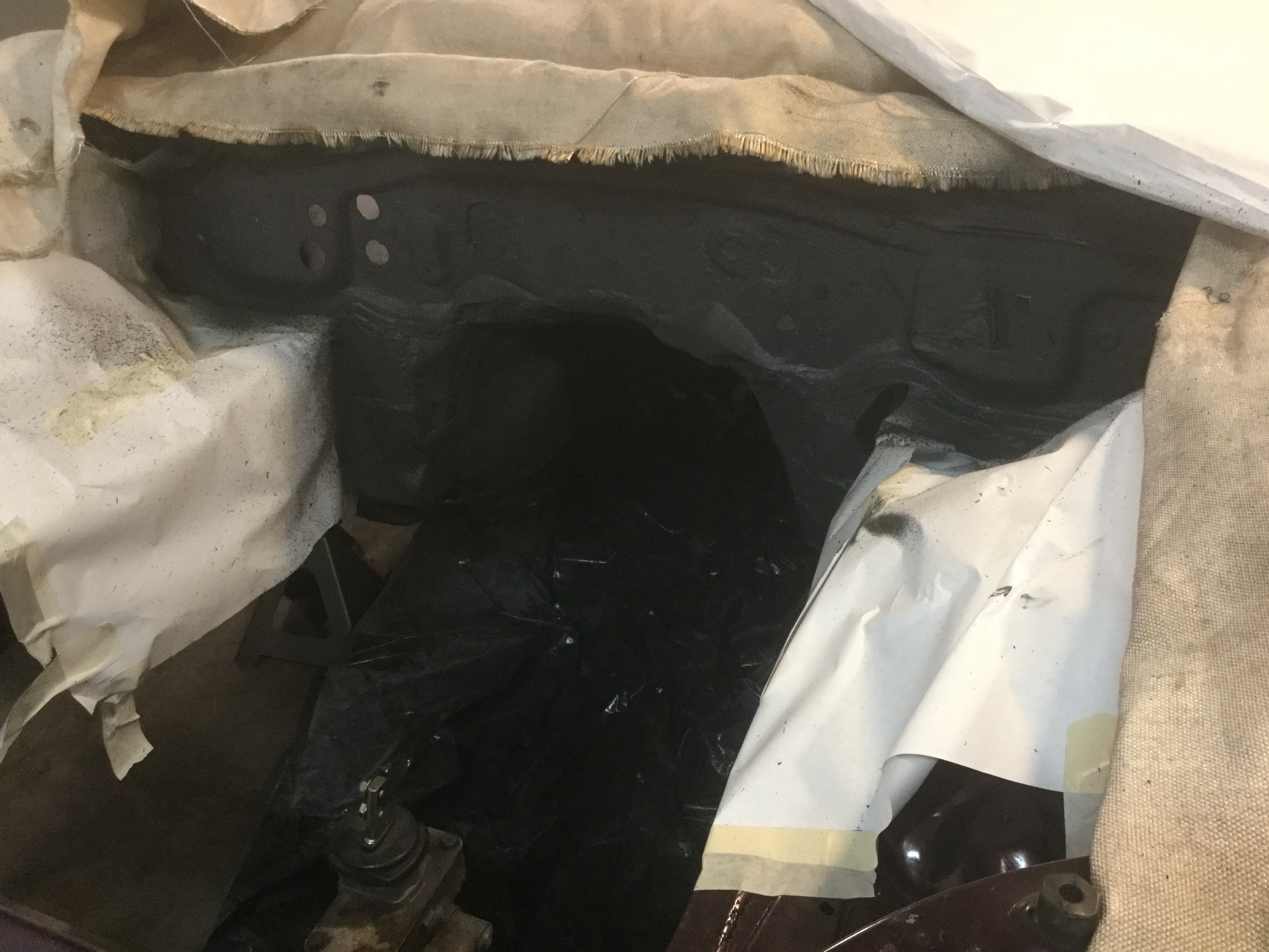
Halfway thru spraying on the Lizard Skin insulation.
Put three coats of the sound insulation under the car and on the engine side of the firewall and inside the passenger compartment.
Makes a pretty good mess but hopefully I have things papered and taped well enough.
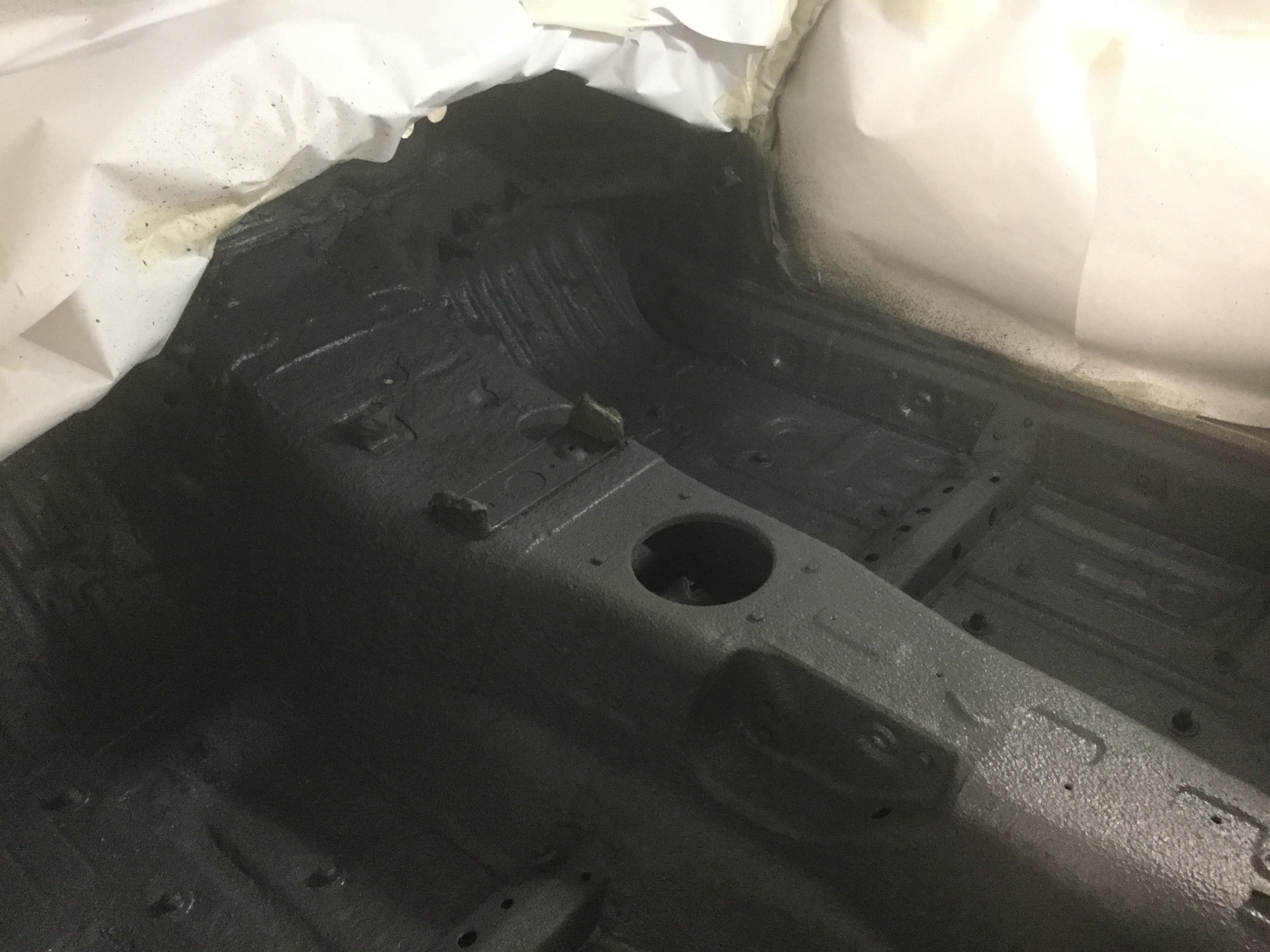
Starting this evening I will begin coating the temperature insulating Lizard Skin over the sound reducer. Too bad they don't have a combined product that would put down both at the same time. The temperature insulating product also mentions sound deadening properties but presumably it gives less sound reduction than the specific sound product.
Should be outstanding when it is all done.
Interior noise has been the biggest annoyance with driving the Miata.
Once it gets running and I get the time to do some drives, hopefully I will be able to report back that the coating is worth the money and time.
Rather than taping up the holes I simply bought some metric bolts and nuts and installed them on everything that has threads.
Two gallons of each is really generous (and expensive).
1 gallon of each would have gotten the job done because the Miata is a really small car.
Edit;
Since the sound reducing coating was sprayed in a whole bunch of locations, my intention is to focus on the potential heat transfer areas to lay down the temperature reducing coating. Specifically, both sides of the firewall and the exterior (underside) of the floor pan where the exhaust system and headers are located. There is also a heat shield bolted to the underside of the trunk that shields the trunk from the muffler heat that will get one coating of just the temperature control coating. I will put one thin coating of the temperature coating everywhere I think there might be some heat soak.
Put three coats of the sound insulation under the car and on the engine side of the firewall and inside the passenger compartment.
Makes a pretty good mess but hopefully I have things papered and taped well enough.
Starting this evening I will begin coating the temperature insulating Lizard Skin over the sound reducer. Too bad they don't have a combined product that would put down both at the same time. The temperature insulating product also mentions sound deadening properties but presumably it gives less sound reduction than the specific sound product.
Should be outstanding when it is all done.
Interior noise has been the biggest annoyance with driving the Miata.
Once it gets running and I get the time to do some drives, hopefully I will be able to report back that the coating is worth the money and time.
Rather than taping up the holes I simply bought some metric bolts and nuts and installed them on everything that has threads.
Two gallons of each is really generous (and expensive).
1 gallon of each would have gotten the job done because the Miata is a really small car.
Edit;
Since the sound reducing coating was sprayed in a whole bunch of locations, my intention is to focus on the potential heat transfer areas to lay down the temperature reducing coating. Specifically, both sides of the firewall and the exterior (underside) of the floor pan where the exhaust system and headers are located. There is also a heat shield bolted to the underside of the trunk that shields the trunk from the muffler heat that will get one coating of just the temperature control coating. I will put one thin coating of the temperature coating everywhere I think there might be some heat soak.
Last edited by BGordon; May 24, 2017 at 11:39 AM.


