When you click on links to various merchants on this site and make a purchase, this can result in this site earning a commission. Affiliate programs and affiliations include, but are not limited to, the eBay Partner Network.
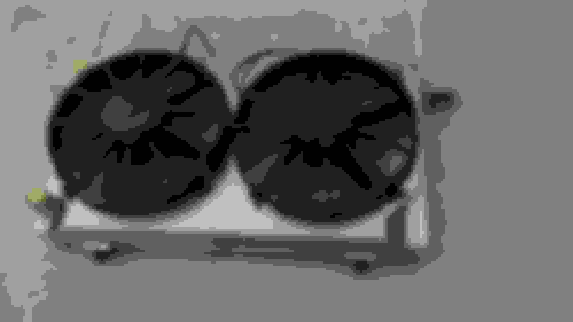
I got my shroud back from the sheet metal shop that did the brake work for me. Best $15 I ever spent. Pretty exciting, i cant wait to weld this up. I still need to turn a couple bungs down for the top of the radiator and install the riv nuts.
Thanks! I'll tell you, I have really enjoyed all the fabrication work, but the radiator has been my favorite part of the build so far. Very satisfying to design something and see it come to life. My aluminum welding skills are coming along also which is nice.
I wonder if i should add bypass flaps to the shroud.
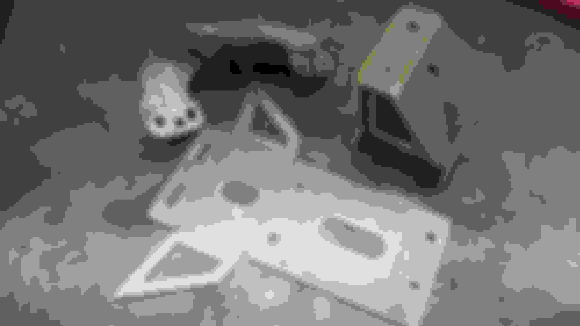
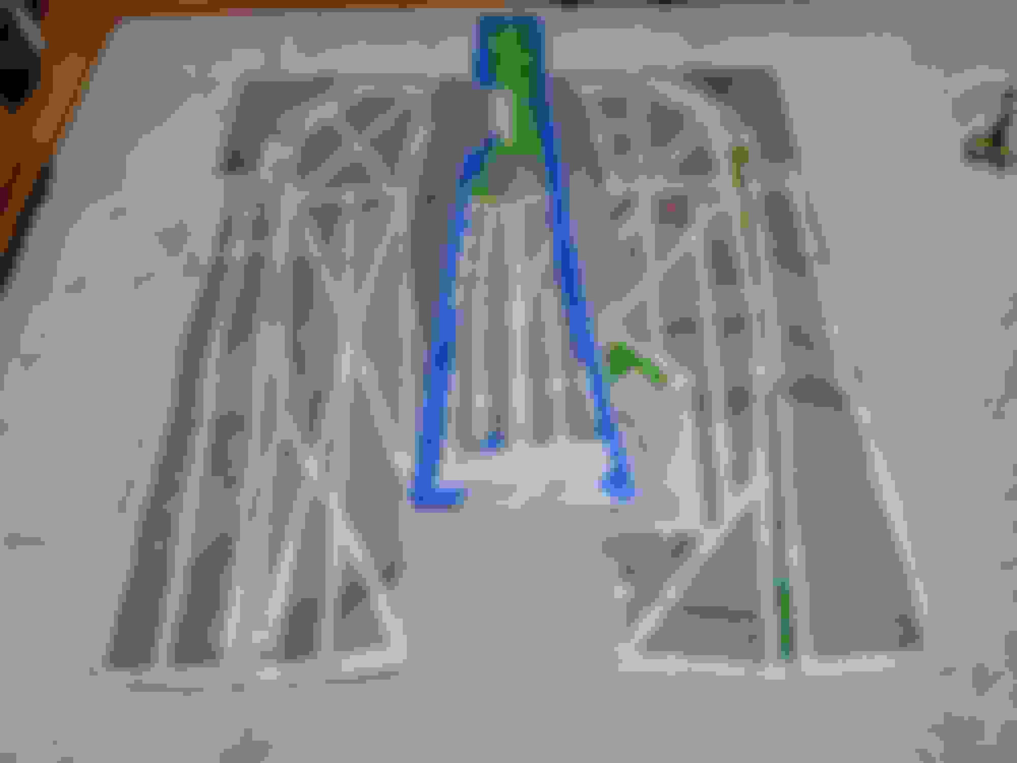
I decided to make a revision to my trans crossmember. I liked the simplicity of the original one but I wanted a little more clearance for the exhaust. I added about an inch, the horizontal bars are now about 3 1/2" above the frame rails.
Thanks! I'll tell you, I have really enjoyed all the fabrication work, but the radiator has been my favorite part of the build so far. Very satisfying to design something and see it come to life. My aluminum welding skills are coming along also which is nice.
I wonder if i should add bypass flaps to the shroud.
It would be easy enough to do the flaps, just some pieces of rubber riveted or bolted to the shroud. The flyin Miata shroud I have has them though they appear to be just bonded to the shroud. Two approx 1"x1" square holes side by side at the top and bottom. Not sure why not just make one big hole.
$15 to do the water jet cutting? That does sound cheap!
$15 for just the bends, the local sheet metal shop charges $3 per bend.
If the flap material is too flexible, it could be pulled through the hole when the fans are running... Probably why whoever designed that other shroud you mentioned made 2 squares instead of one.
Trying to keep the engine bay clean... Drilled a hole in the drivers side under the dash and routed them under the fender. I've heard some folks call this a wire tuck. I de-pinned the connectors and ran the wires through one of the heater core gromets. I'll add the alternator wire here also. I'll do something similar on the passenger side but there will be a lot more going on with heater core lines, radiator vent line and eventually the AC lines. Finished welding up the fan shroud. Everthing including the radiator hoses fit perfect. I love it when a plan comes together. Making a plan for routing the heater core lines and plumbing for the remote resevoir/filler/expansion tank. I'm going to mount it in the passenger side cowel and relocate the wiper motor to the drivers side cowel.
Relocated relays and engine bay fuse block. I've wanted a rivnut tool for years but it was always hard to justify for the odd nut that i could just weld on. I've used this quite a bit for this job, i'm glad i have it in my toolbox now.
I designed these the other day to work better with the 3 series BMW sway bar... The mounts move back because the M3 arms are shorter. Also moved the mount points inboard 1/4" on each side and down 1/4" to better clear the crank pulley.
The other thing you can see here is the Swagelok 10mm to 3/8" adapter union (compression fitting) to adapt the Fbody power steering line to the miata PS line. Part number SS-10M0-6-6
The sway bar is a 90's bmw 3 series E36 (non-M3) bar. This one is from a base model and its a 24mm bar and its 38 1/4" wide where it bolts in with arms that are 7.9" long measured from the center line of the mounts to the center line of the bolt holes. The "sport suspension" cars get 25.5 or 26mm bars. My stock NB sway bar is a 22 mm bar with 8.6" arms and its roughly 40 1/4" wide where it bolts in. The ends of the arms are at a different angle because the NB sway bars dont point straight back... so the NB endlinks don't work. I cut and welded my NB endlinks for mockup but now I'm running adjustable endlinks from 949 racing. These particular endlinks also include 1/2" thick spacers which help to keep the bar vertical. The stock BMW mount is around 2" wide, I'm using a Prothane brand greasable bushing 19-1167-BL which is around the same width as the miata bushing.
Been making good progress on my exhaust despite the onset of summer (hell season) here in florida. Those are dual 3" tubes that I'll connect to the kooks/v8r longtubes with band clamps. I cut a 2 1/2 x pipe in half and made a splayed rear section for it. Those are vibrant resonators. I was able to keep the stock bracing under the diff with the exception of the two side pieces which i need to slightly modify. I intended to run a pair of QTP cutouts but they are too big for this location... I'm going with magnaflows but am curious about hooker aerochambers... Maybe next time. I made a cardboard template from the original notch in the bumper cover. Just flipped it over and measured back the same distance from the wheel opening. Not sure what this saw is called but it worked perfectly to rough it in within 1/8" of my cutline. From there, i got it close with the flap wheel, then finished it by hand with a piece of 220. Came out nicely I think.
I finished up the forward / x-pipe section. Added the interlocking 3" flex joints, vacuum cutouts, 3" turn downs and a hanger. The flex joints make it easy to get the assembly off the car. These cutouts fit with a little clearancing of the tunnel. The Kooks/V8R headers hang a little below the scrub line in order clear the bellhousing. I angled the pipes up a little to get the rest of it up into the tunnel. Everything behind the flex joints is above the scrub line. I still need to remember to clearance that right flex joint, its almost touching right now. These are the vacuum cutouts. Great quality and value. If you can wait 4-6 weeks they are about $45 off amazon
I picked up this fuel pump bulkhead kit from CJMotorsports.com. This is the kind of thing you could spend the better part of a week inventing/designing and cutting on a lathe but for $70 why? This is a great value and it allows up to 10 gauge wire and 6 pins so I can run dual pumps in the future if I want to.
I cut the old passthrough out with a hole saw, welded the new one in and welded the bracket for the fuel gauge sender back on at the same angle.
I may upgrade to a larger bulkhead fitting in the future but I think I'm good with the stock ones for now. I originally ordered one of the wrong part numbers and got a leftover one from a buddy... 2 different colors, no one will see it anyway right? This bothers my OCD, lol.
Also some progress in the wiring, the distribution blocks, relay/fuse box and circuit breaker are from amazon, the metri-pack connecters, pins, and relays are from mouser. One note that may not be obvious is the relays i used have a resistor in them to reduce the voltage spike on the control circuit when the coil current is switched off. This is a good idea / possibly mandatory to protect the Holley ECU. The circuits are all the ECU related circuits that require relays... fan1, fan2, fuel pump, ignition, and exhaust cutouts, with one slot if i want to add something in the future. I mounted everything with riv-nuts and found a spot for the assembly next to the fuel tank.
So these are the Parts/Tools I used for wiring from my battery to my fuse/relay panel. The wiring for the rest of the car is still ongoing and I can give you those parts later. This panel is specifically for the high current devices that my Holley ECU will control... fuel pump(s) Fans, Ignition, exhaust cutouts.
I already had some of this stuff but I've researched the part numbers for you.
for 6 AWG Terminal ends
I reused the original battery body ground wire, I terminated it with a 3/8" x 6 AWG Lug on the battery side (i think), it connects to the body inside the trunk in the stock location, then runs to the negative buss bar and terminates with a 1/4" x 6 AWG terminal as below.
note that the fuse box does not come with relays or fuses, it does however include the connectors you need to wire it. I would have gone with the 2nd one if I had found it before I built min. It would have made for a clean through-panel install. (there are others also)
10 AWG GXL Primary Wire and 18 AWG for Fans Fuel Pumps and control circuits. *TXL would be a better choice for the 10AWG wire as it will fit the metri-pack connectors better, you can also buy your battery cable from these guys. Relays (with resistor)
for Metri-pack 280 up to 10AWG, I used this tool for the larger wire sizes. Fuel Pump Bulkhead kit
I think that wraps up whats shown in the picture you asked about. Let me know if I missed anything. I picked up the components to build an 8-pin metri-pack 280 connector and 3 2-pin metri-pack 280 connectors from mouser. I may have also used connectors from mouser for the 10AWG wires in the relay box. Let me see if I can find my invoice and I'll work on a list of that stuff also.
This is the installed fuel pump with new fuel pump bulkhead It took some looking but I found a couple of wiring harness specific grommets from Mouser. I installed the larger one for the part of the engine harness that wraps around the bottom of the engine... starter wires, 02 sensor, knock sensors, cam/crank sensors, alternator wiring. I used the OEM engine harness grommet for all the wiring on top of the motor. This is the smaller grommet for the body harness that I'm tucking inside the fenders. The circled area is where the body harness will come through. I've been working on the Heater core hose tuck in parallel with the wiring. Here is my hose routing from the cowl around to the water pump. Eventually I'll add AC, so I'm making sure to leave room for routing those hoses. The hose fittings are all aeroquip socketless -10 AN and the tube ends are -10 an male - 5/8" tube compression fittings. I drilled and tapped the water pump for -10 AN to NPT fittings. I made up a 3d model of my washer tank, printed out templates, made up a mockup from an old political sign, Traced the templates on a sheet of .090 5052. I cut the aluminum with a jigsaw and cleaned up the cuts on a harbor freight belt sander. And here is the part fully welded up and installed. I don't weld aluminum often and its easy to fall out of practice. This part was a huge pain but I'm good with the results. Building a larger/taller tank and putting it on the firewall would have been a more optimized design but I want to keep the firewall clear. So here it is with the stock plastic cover (slightly trimmed) in place. The bulkhead fitting one on the left is the return line from the top tube on the heater core. I cut the end of the bulkhead fitting off and welded it to the bottom of the remote fill tank. The one on the right is a 90 degree bulkhead fitting and it goes to the rear port on the water pump. A 120 degree AN fitting would have been a little better than the 90 here. I had the blue ones on hand already... couldn't bring myself to buy more fittings for something that is not normally seen. Here are the heater boxes mocked up with everything fitting. I've finished maybe 80% of the wiring at this point. That mess on the passenger side floor board is the bulk of what I have left to do. Here are my harbor freight wire crimpers/now tube beading tool in action.
I installed DEI tunnel Shield under the car. ASIN B000CEO5W8 and B000CEM3O0 to do the area between the frame rails. This is a very high quality product but there are things you need to know. First, it is not like working with that rubberized sound deadening material that goes under your carpet. This uses a much thicker aluminum foil over a fiberglass material with a very aggressive adhesive. To give the adhesive its best chance, I started by cleaning my 140k mile floor pan multiple times with mineral spirits, prepped it with scotch bright pads and sand paper, then and gave it a fresh rattle can paint job. I let the paint cure for a week before installing the tunnel shield. Once the adhesive makes anything more than the lightest contact, its difficult to remove without separating the fiberglass layer so get it right the first time. I created a template with newspaper and masking tape and cut the tunnel shield material to the template. I bought an inexpensive pair of scissors (ASIN B00LSWLAA8) and they made it through the job... I needed to stop periodically to clean the adhesive and fiberglass off them. The cut edges are sharp so wear some gloves! I roughly contoured the tunnel shield to my project BEFORE removing the paper backing. I then carefully positioned my work and gradually removed the paper backing while rolling it in. Work slowly and deliberately. The foil is flexible enough to roll into and around contours but it does have its limits. The roller I used: (ASIN B07X5SV5FD), its a good quality product that should last through many projects. You'll need to seal the edges since water could get into the fiberglass layer. DEI recommends their tape for this purpose but several people had negative things to say about the tape. On the recommendation of another enthusiast, I sealed the edges with RTV. I used loctite grey #5699 ASIN B0794BYCZ2. The pressurized container works in any orientation and made it easy to apply a consistent bead. Tip: mask the edges of where you apply the silicone to have straight, tidy edges. Again if you work slowly and deliberately, you can get good results. I worked in the silicone with a finger and wore heavy Venom Steel nitrile gloves to keep the chemicals off/out of my body (ASIN B00Y2OFGMW). Yup, the car is blue now.
I guess I missed your previous post on the coolant lines, but nice tip on the DIY beading tool. And nice clean work on the tunnel, don't want to do that twice.
Installed a starter blanket. Trimmed it to fit better. It's got Velcro but I used some safety wire to really tie it down. Summit Sum-350118-1 You can see my 1� setback plates here. The V8R headers only gave me at best 1/4� of clearance to the driver's side knock sensor. Someone suggested to move it forward to this position so that's what I did. I had to modify the driver's side mount for clearance. Speaking of mounts and headers and setback plates, this is where you run into clearance issues with running the cooks/V8R longtubes with the Monster Miata subframe. After I moved it back an inch, there is 3/4� of clearance to the front mount. I moved it back a little further than I needed to. If I had it to do over again, I�d countersink all 4 holes in the plate and move it back 5/8� instead of the full 1�.
 03-20-2019, 10:56 AM