When you click on links to various merchants on this site and make a purchase, this can result in this site earning a commission. Affiliate programs and affiliations include, but are not limited to, the eBay Partner Network.
Yes, the starvation issue was very specific to one particular turn, and only happened at that turn once the tank was about 1/2 full. I agree the g-loads didn't seem high, but it was a long left hand sweeper, then slightly uphill into a quick right hander. It was that transition where the fuel starvation was happening.
I've since changed out the filter sock to one closer to OEM. I've read alot of comments that the OEM filter sock must be used, or you'll see issues. Others have also said you can practically run the tank dry in the proper configuration. We will see.
Somewhat bad news to report. Back when I first put the engine together, and swapped the timing chaing, I got the cam timing off. That was addressed and car has been fine since then. When I pulled the heads off this week I found that all 8 intake valves contacted the pistons, putting small valve reliefs in them. In talking with my engine tuner, this isn't a big concern and I could clean them up and run them. I'm a bit worried that some damage may have occurred, and with the higher compression and power I'm aiming for with the head/cam upgrade, this could create an issue. Throwing a piston would damage my new heads, etc. and I'd never forgive myself.
So I'm looking at forged pistons, I can handle that. In talking with my tuner, resizing the "cracked" style connecting rods is difficult to get right. I'd not heard this, so I'm making some calls to places to see if anyone can confidently do this. If not, I may also need to upgrade rods. Since most aftermarket rods are slightly longer than the stock 6.098" stock rod, I'll need to take into account how this will affect piston valve clearance, compression, etc. Things could definitely escalate quickly.
As far as the rest of the engine, it seems healthy. Head gasket showed no damage, pistons seem good other than the valve contact, cylinder walls are good, cams, lifters, bearing surfaces are also good. I found a bit of shop towel clinging to the oil pickup, which could have also created an oil pressure problem.
I'm using this book for reference
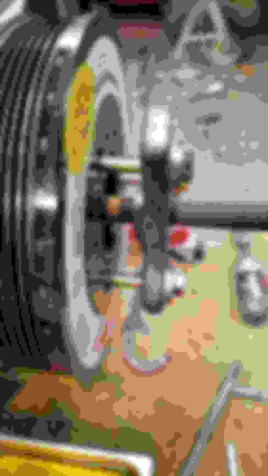
Had to pick up some bolts of the right thread and length to pull the ATI Balancer off. Amazingly, ATI doesn't provide much detail on this in their guides, but I did find the proper thread size posted by someone online.
A question on the ATI balancer.
I am running a stock Corvette balancer because it matches the belt location for the CTS-V accessories.
Do you have any reason that it would be advantageous to switch out the balancer if I decide to do a cam upgrade in the future?
Not sure whether a cam upgrade would specifically benefit from an ATI balancer, but the selling point of these balancers is they can benefit any engine. The more power you add, the more they can "free up" power as well as reduce engine vibrations so that could help with engine longevity.
I upgraded b/c I needed to switch to the shorter Corvette balancer anyway, and it didn't make sense to buy a new OEM balancer when compared to the ATI.
Sorry to hear about the bad news but oh well, its only money right?
One thing I notice here, I ran the OEM strut bar for years until just recently. A point of advice I'll give you is that you need to triangulate your additional bars more towards the actual mounting points of the bar. I think where you have them isn't going to net you all the gains possible with that type of change, it will end up flexing the bar more. I have considered the same modification to the bar.
One thing I notice here, I ran the OEM strut bar for years until just recently. A point of advice I'll give you is that you need to triangulate your additional bars more towards the actual mounting points of the bar. I think where you have them isn't going to net you all the gains possible with that type of change, it will end up flexing the bar more. I have considered the same modification to the bar.
I think that's a good suggestion. I had originally planned on attaching to the round section of the bar as it seemed stiffer than the stamped metal "legs". But moving them out a bit shouldn't be too hard. The real thing I'm unsure about is how to attach to the car. You know this from cutting away part of the rain gutter area to add your blower. That section is not very stiff, and would benefit from some bracing. I would like to weld gussets to brace the flexy section of the rain gutter. But behind the body of the car is sound deadening or heat shield material which I know about b/c I removed the dash. The heat from welding could potentially start a fire with this material. So I'm thinking about how to brace this without welding to the car, or just attach to the rain gutter and see if improves without any bracing.
I don't think you are going to get much out of just attaching to the cowl panel, like you said its fairly flexible. If you look at the cobalt bars, they provide a plate for the back side to spread the load out, but my opinion is not high of the plate at its size.
If it were me in your situation, I'd go with the spreader plate idea, but on a larger scale. I'd get a piece of 1/8" angle, maybe in 1" leg lengths, and bolt it on the back side as wide as you can with multiple bolting locations. This would spread the load out a good distance, and give you a substantial increase in strength at that point. I'd do the angle because even thicker plate can flex if its just plate, but the angle has the 90 degree leg to it will add a lot of strength for not a lot of weight addition.
Just an idea... Perhaps you could put a member (or more than one) between the flimsy cowl panel and the rear firewall, and attach using *epoxy* instead of welding. If it was me, I'd really be trying to make the firewall take the load.
Just an idea... Perhaps you could put a member (or more than one) between the flimsy cowl panel and the rear firewall, and attach using *epoxy* instead of welding. If it was me, I'd really be trying to make the firewall take the load.
Well, that's the direction I'm now thinking about thanks to stng's post to his thread about panel adhesive which I just read. I've not tried any of this stuff before but it seems within the realm of the DIYer. This stuff
seems to the best out there, thought I wish they sold in smaller quantities. I could try one of the cheaper or smaller quantities since this really isn't going to be under that much load. Or an epoxy or good 'ole JB Weld which I have some a few tubes of.
But I agree on the angle iron to stiffen the front cowl. Back it up with some gussets bracing to the horizontal and vertical sections of the actual firewall section of the body, while not interfering with the wiper arms, weld that to the cowl brace, and then use adhesive where needed. Then I can just work forward and attach the new legs of the strut brace to the now stiffened cowl with some bolts for easy removal.
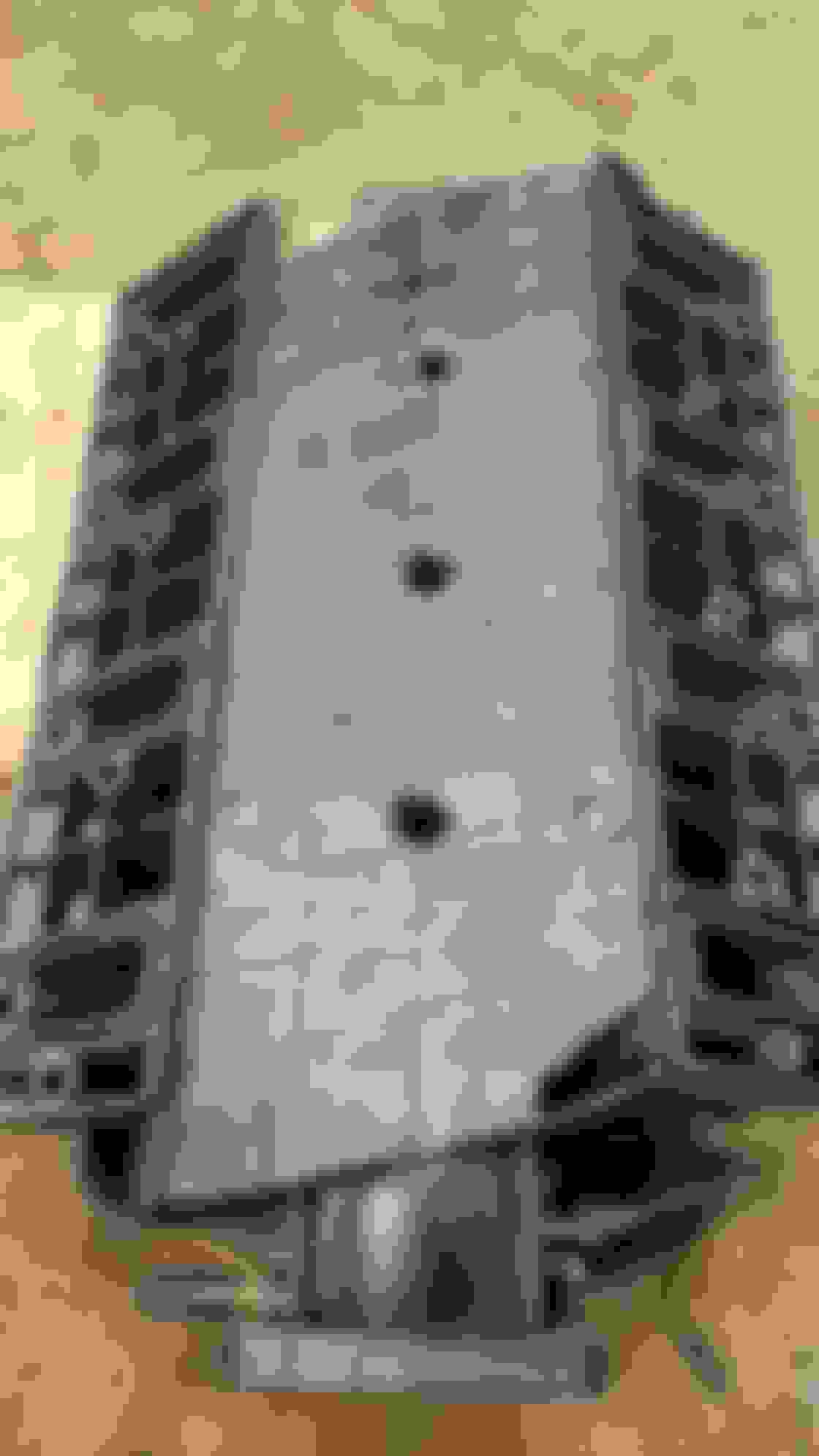
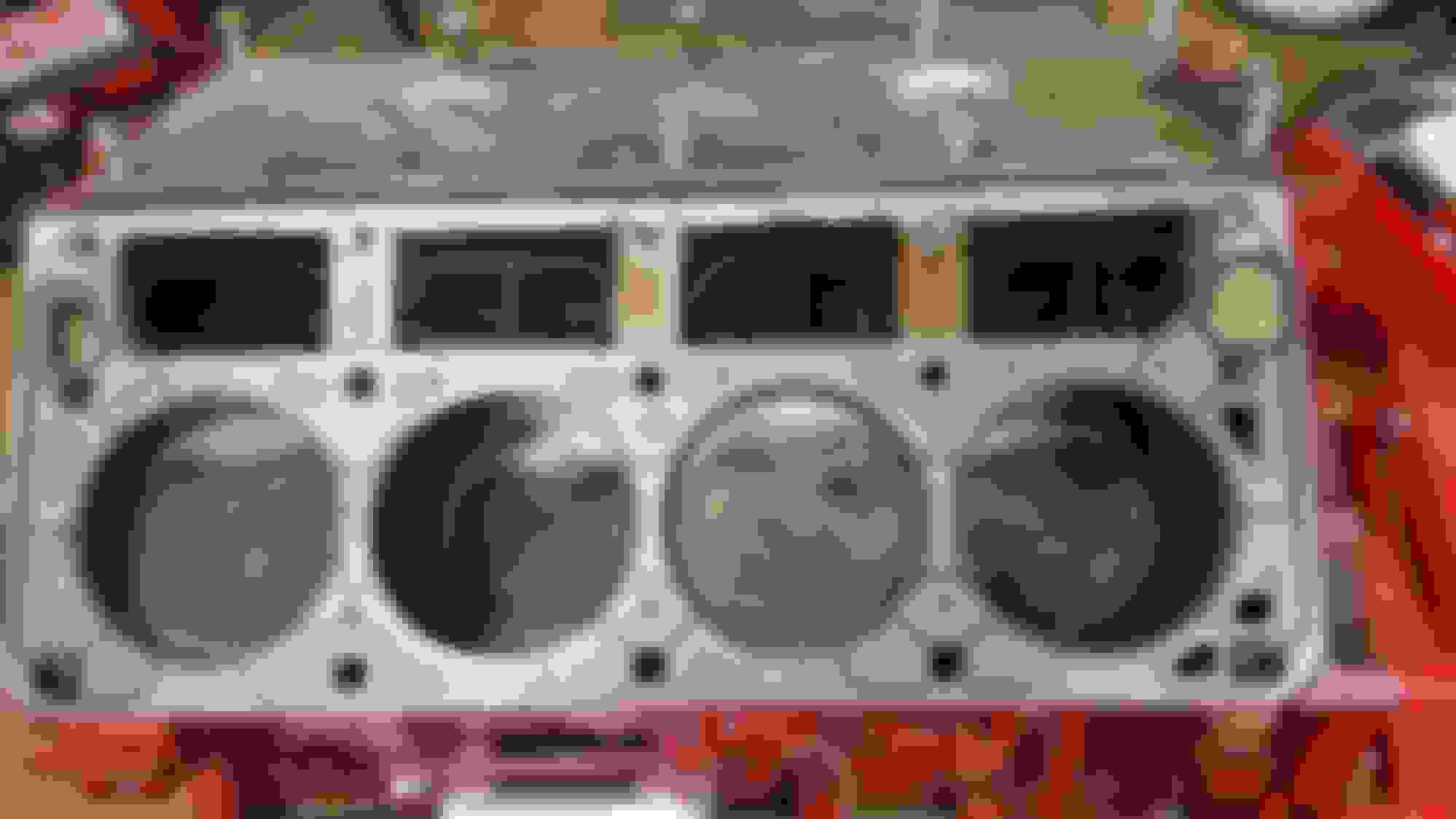
Here are some add'l pics of the piston tops with the valve relief. Seems to be the opinion of others that these were fly cut into the piston, rather than piston to valve contact which would have done some valve damage. It'd be nice if the valve contact wasn't the case, but it also makes me curious why this was done, or what other surprises are lurking in this LS1. Anyhow, I have my rods with a local shop to check the clearances so I can see if they are reusable with the ARP bolts installed. Then I can buy pistons and get a move on.
Spent a couple hours on the trunnion upgrade kit. You start by pressing out the old trunnion. My newish shop press made this part cake, though you could get away with just using a vice, they don't need that much pressure.
They advise on what socket sizes work best
Then once apart, you just toss the old stuff, but you can see all the little needle bearings that puke all over your work bench. This is what your oil pan might look like after you lose a trunnion at high RPM.
The new trunnions ride in two brass sleeve/bushings on either end, and stay in place with snap rings. Keep them oiled up as you work, and put them in a ziploc bag with some oil. You don't want to use any carb or brake cleaner after assembly as that will remove the oil in the bearing and they might seize up.
Used an old head bolt with a small slit cut down the side as a thread chaser.
2 or 3 holes were pretty gummed up, one quite a bit. This is the kind of trash you can pull out
Also used my bench top wire wheel to clean the valvetrain assembly bolts. The red stuff you see under the bolt head on the right is a sealant since half the holes on each head open directly into the intake tract. If you don't use sealant, it can create a vacuum leak. Clean off the old sealant and use new telfon-based stuff when you bolt them in.
I have seen valves tap in their own relief, I built a 340 D0DGE while I was going to school for my 70 DEMON, In a rush I installed the pistons backwards. I drove the car for 2 months with out ever really stepping on it. Then one day after 5000 km I decided to run hard through the gears, was the top of 3rd gear at 7800 RPM when it let go, broke the head off the #6 intake valve and turned it sideways and made it one with the head, LOL. Other 7 pistons now had an extra valve relief that was pounded into the piston tops with the forged aluminum slightly rolled on the edge like yours look. Check the diameter, if its the same as the valve head it was pounded in hardcore style, LOL. Just my 2 cents and personal experience with this exact problem, luck you didn't break,
Past week was spent doing some welding and engine teardown.
I worked on some gussets to brace the cowl where I will be extending the strut tower brace. I used some cardboard to template the metal gusset and started cutting and welding.
Closeup of one of the two braces. Had to shape it to clear the wiper linkage. I notched out the angle piece that runs the length of the inside of the cowl. The angle is held in with some bolts.
Pic of both braces and of the angle iron attached to the cowl. I plan on attaching the legs from the strut tower brace very close to these gussets. The angle piece runs longer than I think it needs to, but that's what I started with, not knowing where I would eventually end up. I used some cardboard with a similar thickness and dimensions to the 1/8" steel. Laid out where they will attach to the cowl, and to see how much I'd need.
I bent some steel strap to form around the metal gusset, and tacked it as I went. Had to use some clamps to really hold it tight to the gusset shape. Turned out pretty well. All metal parts are currently getting a few coats of POR15.
. The quantity and price seemed just right for what I need. I'll need to remove paint in the cowl area where it will attach and probably get my garage temp up a bit into the 60s when I do this. You can use a heat gun to accelerate the curing. More to come on this process.
In other fabrication news, I had come across this thread and a particular post about the V8R subframe and potential weaknesses https://forum.miata.net/vb/showpost....9&postcount=25. I really just stumbled across this issue, and feel lucky I did since I do some tracking with the car. Seemed like the right time to address anything especially with the engine out and with the other structural bracing work I'm doing.
Keith Tanner of Flyin Miata says: I have broken two tubular front subframes and have caught another one that was starting to go. There was another tubular subframe failure at MRLS in 2017.
Two of the failures were the steering rack mounts. This is a bad failure as it can lead to a loss of steering. One crash. Adding some gussets to those rack mounts is a good idea.
The other two failures were at the rear control arm mounting points. This sees a lot of side load under braking and it's weak. Look at the factory subframe and the braces that Mazda added over the years. It's stiffer than the tubular one to start with and Mazda started added braces in this very area in 1992. It's hard to put a lateral brace between those mounting points with the V8 because of packaging. The best way to check it is easy - just look down the length of the square tube section that runs longitudinally and look for bends. Eventually, it will start cracking in various places and can even rip the mounting points out of the chassis tub. I would recommend fabricating a brace if possible.
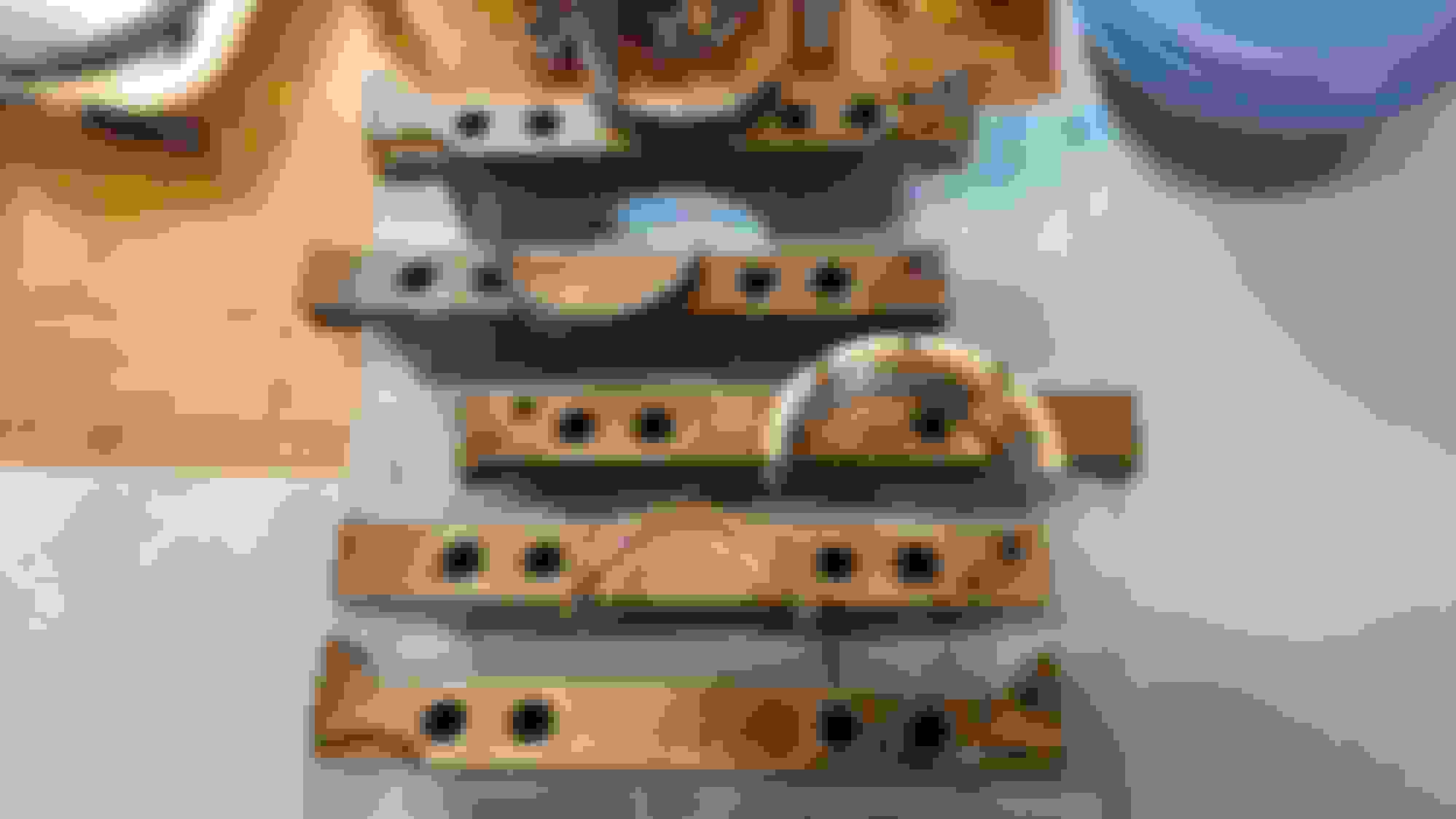
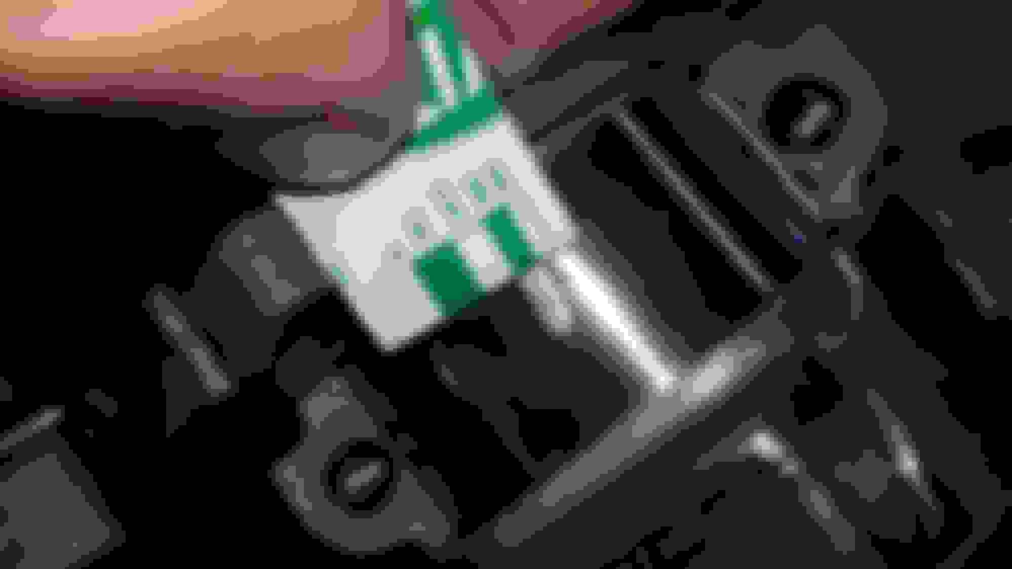
So I added some gussets to all 4 control arm mounting points and to the steering rack mounts. Since I had done the rack mounts myself way back, I felt the added strength was probably a good idea.
More gusseting of the rack mounts. All these spots were hard to reach, so the welds look a little sloppy but they will do just fine.
couple coats of POR15 and a final coat tonight of a gray color similar to the subframe. A lighter color paint here will help see if there is any cracking starting to develop.
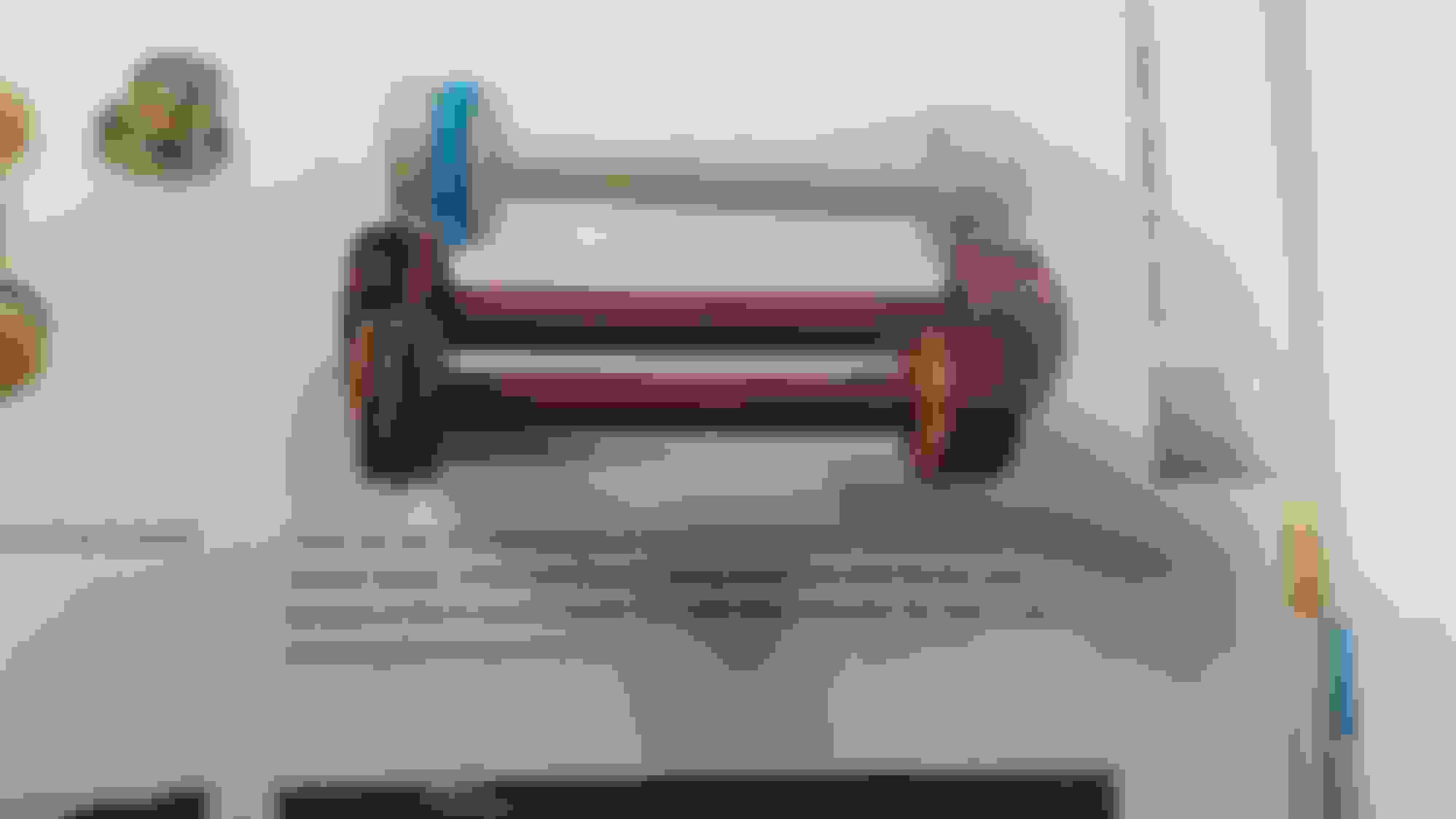
Once the engine is back in I will work on some bracing to go from one side of the car to the other, connecting the two rear subframe chassis mounting points.
On the engine side of things, I heard that my connecting rods are in good shape, and with the ARP bolts torqued to spec, will not affect the oil clearances on the crank. So I went ahead and picked up a set of Mahle Forged pistons that will ship directly to the machine shop. He will install the new pistons since the wrist pin is a press fit. Tomorrow I will drop off my crank so he can balance the whole assembly. Once I get it all back, I should be able to start by gapping the piston rings which will probably take some time, and then start reassembling.
Before I dropped off the crank I wanted to see if I could check the main bearing clearances using plastigauge. Turns out the bearing clearances seemed spot on, which was a nice feeling. LS1 bearing clearances should be about .002" and the plastigauge seemed to read pretty much that on all 5 bearings.
Finished up the strut bar modifications. Turns out I didn't realize the panel bonding adhesive required an applicator gun, and that the gun would cost $60... So once I received the gun
I was able to bond the gussets to the car. The adhesive can take up to 7 days to fully cure, but I waited about 3 days before I started back working on the mounts. The epoxy seemed very hard by this point and very strong. I decided to go with some larger angle iron, but also to shorten it a bit so it would only be as long as the distance between the two gussets, and a few inches past on either side. you are supposed to clamp the piece tightly for a few hours, but I couldn't do that so I used some self-tapping screws to attach the gusset tightly while it cures, and just left them in. The adhesive also provides a water tight seal.
Once cured I welded the gusset to the cross brace. By this point I could tell the cowl was very stiff. I welded in the diagonal braces you see below so that the load was going directly where the gussets were located. I created some mounting tabs that would would bolt through the cowl and into the cowl brace. With them bolted tight, I used some cardboard to find the right length and angle for the cuts on the angle iron. Fitted and tacked in place, I fully welded everything with the brace out of the car and painted it. Lets hope it provided some measurable amount of bracing.
I was also able to use the driver's side shock mount brace to make a simplified version of the master cylinder brace, using pieces from the old brace.
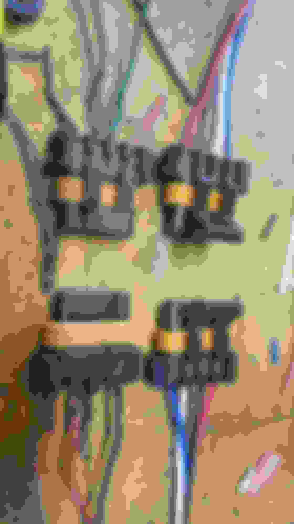
In a small wiring project, I replaced two of the ignition coil connectors since the tabs that keep them secured had broken off and I was using zip ties to keep them secured. I purchased a pack of 10 off ebay, and I have 8 left if anyone needs one.
I did some engine block cleanup in preparation for the completed pistons/rods/crank that I hope to pick up this week.
I pulled all the main bearings and caps, and dunked them in a tank of mineral spirits to let them soak, along with some other parts. I used an old toothbrush and some pipe cleaning brushes and green scrub pads to clean up alot of engine grime trapped in different spots. The dollar store is a good place to pick up cheap brushes that you can get covered in solvents and grease and throw away or keep for future engine projects. harbor freight has an engine cleaning kit with small diameter brushes with attachments to your drill, but I had an old set I picked up years ago that I continue to use.
Kept all the bearing shells with the corresponding main cap.
I still need to do some further cleaning of the block and all the oil passages, lifter bores, etc.
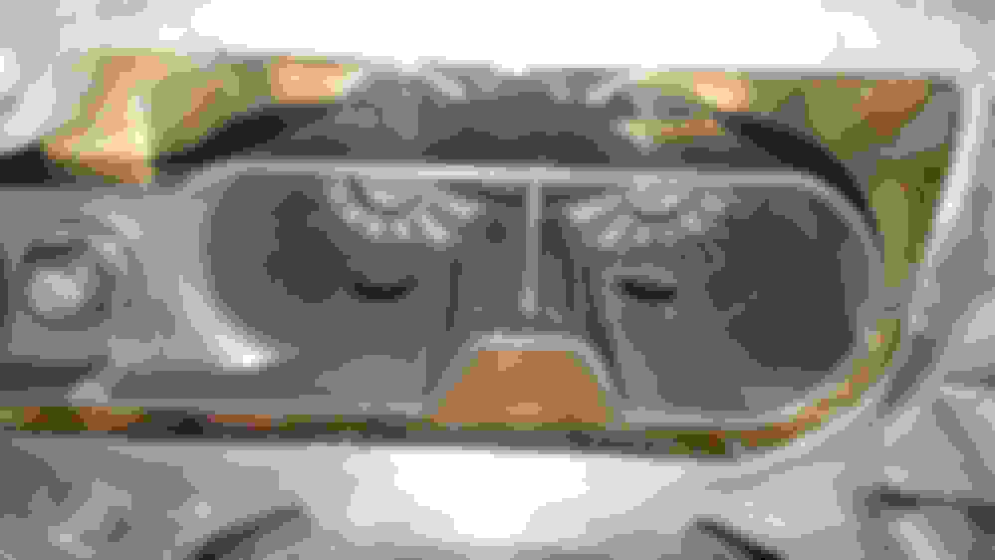
The last thing I did for today was to hone the cylinders. I used a Flex Hone in a 240 grit as recommended in a 4-1/8" size, one size larger than the engine bore which is 3.898".
I need to call the piston maker, Mahle, and see if they recommend a finer grit final hone (maybe 400 grit) given the moly coated rings the pistons came with - which I haven't seen yet. I coated the honing stones with a cutting oil, set the hone on top of the cylinder, and start spinning it before you push it into the cylinder. I went up and down about 10 times in a consistent, but pretty quick motion, and keep it spinning as you pull it out of the cylinder.
The cross hatch pattern should be where the diagonal "scratches" are 45 degrees to each other. I think the flash on my camera makes the hone look a bit rougher than it is.
Some things I read point to cleaning the bores very thoroughly as being the key. If you don't, alot of the abrasive material from the honing stones and the metal removed will quickly wear away the cylinder, rings, and maybe elsewhere in the engine. I used some soap and water, and a dollar store tiolet brush to wash down the cylinder and dry them. If I need to do a finer hone I'll do that and then wash it again, maybe twice. Then the whole block will get a wash.
The cross hatch pattern in this pic is the before of the bottom of the cylinder where the rings didn't touch
Next update I'll hopefully start putting things back together.
Thank you for all the photos, documentation, and suggestions. This is detailed really well. Had no idea about the V8R subframe needing reinforcement. I’ll check my “Starbucks runner’s” subframe next time it’s on the lift!!
Thank you for all the photos, documentation, and suggestions. This is detailed really well. Had no idea about the V8R subframe needing reinforcement. I�ll check my �Starbucks runner�s� subframe next time it�s on the lift!!
I ended up giving the cylinders another hit with the ball hone, once I looked a bit closer, I could see that in between the honing "scratches" were some shiny areas from the original finish on the cylinder walls, and that I probably needed to break it in a bit more. I used some ATF this time and spun it in each cylinder a bit longer. Once I was done I was a bit happier with the turnout.
Another thing I didn't cover was the engine plugs. I almost decided not to do them figuring what's the point if they don't leak but realized maybe they would help get any junk out the cooling and oil passages. Picked up this kit from Amazon
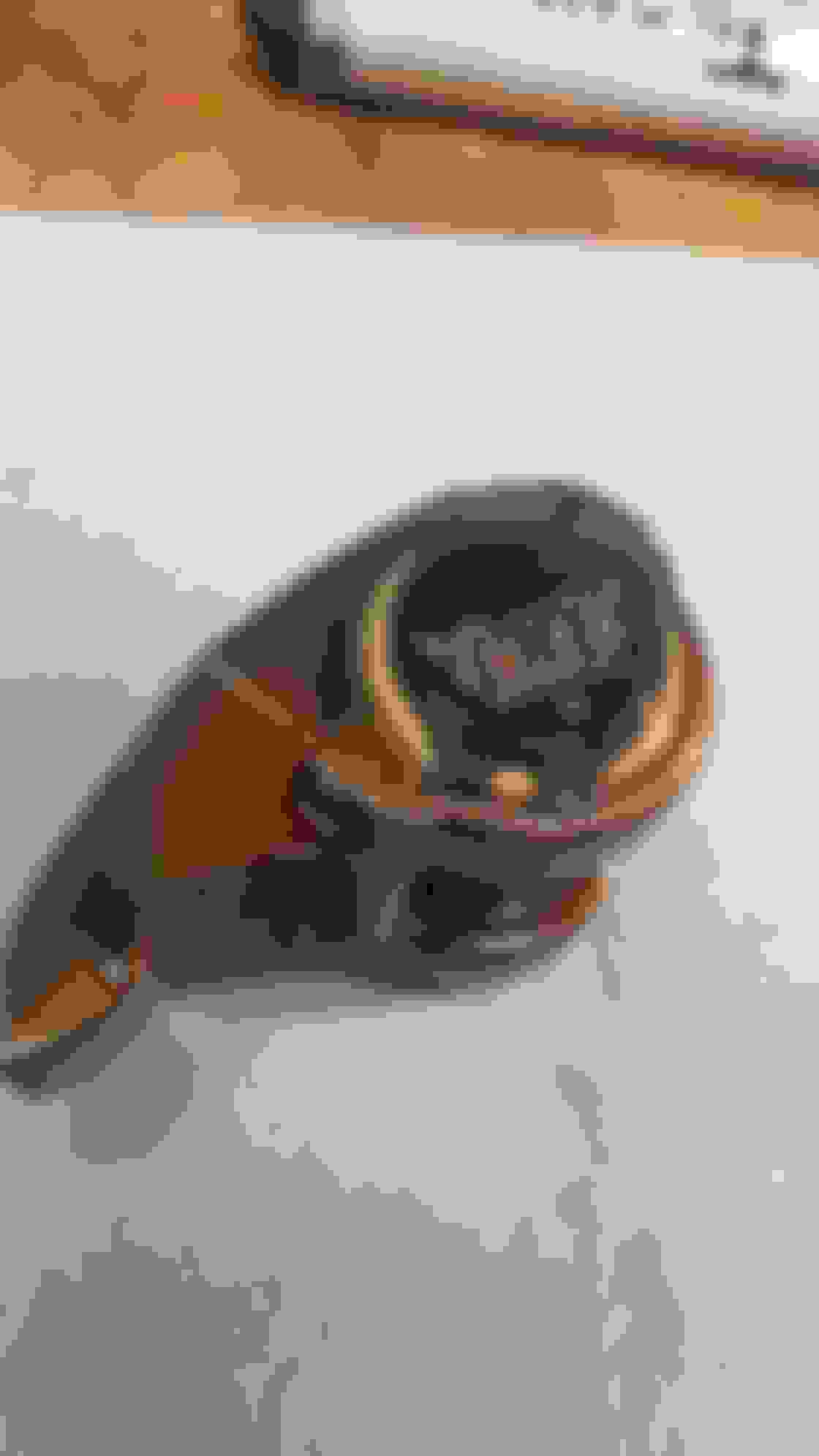
can use a smaller diameter shaft since it's machined from metal so it's less restrictive. It also has tighter tolerances to let less unfiltered oil by when it should go to the oil filter first. Seems like a well thought out piece for the money. When I pulled out my old one I was happy I did as I had the old style.
I picked up the crankshaft, and assembled pistons and rods last week. The crank was balanced and the journals were polished to a nice finish. Turns out the builder the didn't purchase rod bearings like he said he would so I before the day was out, I ordered some from Summit Racing so they'd arrive by the weekend https://www.summitracing.com/parts/CLE-CB663P. With some warm weather on Friday and Saturday I was able to spend some time in the garage getting thing started.
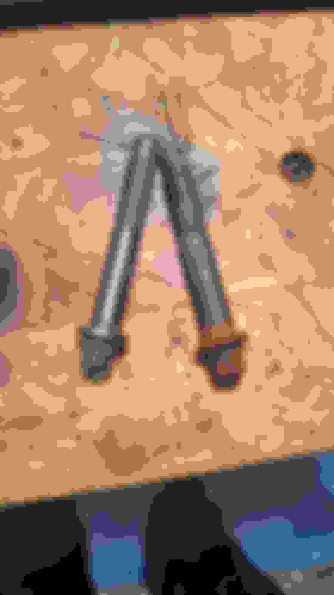
First step was to begin the task of gapping my piston rings using this piston ring filer
. Using the guide from Mahle, I decided to go with a gap on the larger side more towards "Race" as the car will be seeing high RPM for certain periods during track days, and it's better to err on the high side as you don't want your rings binding. Using my 3.898" bore size, and calculated what my range would be between High Perf Street and Track/Drag, which was 0.017 and 0.019". The difference here is so small it's hard to imagine a couple thousandths of an inch making any difference at all. On the second ring there is a larger range, and there is some theory as to whether a larger gap creates less of an issue with cylinder pressure between the two rings, but won't affect cylinder sealing much. I decided to err on the larger side as well around 0.021".
Using the ring filer was a learning curve as the first couple rings took me about 5 minutes each, as I learned how quickly a few turns of the filer, and how much pressure on the ring would correlate to the amount of material removed. That and just keeping the ring positioned correctly so that the filed edge is square to the ring and matches the other side of the gap evenly. I used a fine hand file to get this closer and also to remove any burrs and smooth the cut edges. By the last one I had it down to about 1-2 minutes.
I created my own tool using an old piston and a large hose clamp as a depth measuring tool for the piston ring. This worked pretty well actually.
I labeled the rings as a went with masking tape and then finished out by installing the rings on each piston using a piston ring installer
. Unfortunately Mahle didn't include in their instructions what the orientation of the rings were. There was a marking that I first thought was an E, but soon realized was actually an M for Mahle. Typically any markings or dots indicate that side goes up, but it would've been nice to include a line about that. I did find the information elsewhere on their site.
I had heard that rings should be handled with care as they are brittle and can break if twisted or over stretched. It's important as you're working with them to not catch them on your clothing for example. A few times I almost broke a few as I was quickly moving between my ring filter and the cylinder, almost catching the open end of the ring on the filer tool. I had to slow myself down a few times rather than ruin my weekend with a broken ring.
A couple side by side comparisons of the old piston on the left, and new on the right
I had soaked my main bearings in mineral spirits and scrubbed them down pretty good to remove any grime of which there was plenty underneath where the oil passage feeds the upper grooved shell. They seemed in good condition so I'm going to run them. New ones would necessitate getting the crank, and mains checked for clearances and didn't feel I needed to add to the expense.
Using new OEM main bolts https://www.summitracing.com/parts/CMB-08-0064 I dropped the crank in with some assembly lube and installed the main caps and torqued them down. I would spin the crank after each cap was installed to make sure there was no binding. I found this torque angle gauge to be very easy to use, less prone to moving than a previous one I bought from NAPA. It uses the jaws to clamp to a nearby bolt, etc. and worked very smoothly
Marked all the bolts as they were torqued. Side bolts (not shown) were new. The new bolts come with some thread sealant under the heads to keep oil from leaking to the outside of the block. If you reuse the side bolts you can clean them up and just add some sealant. Since the oem main bolts are just torque to angle (not torque to yield, meaning once they are stretched they can't be reused), you can use them, but some say not to.
Last edited by pj_mcgarvey; 04-02-2019 at 08:26 AM.
Tonight I started installing the rods to the crank. I measured the oil clearances using plastigauge on the #1 and #2 cylinders just to make sure nothing weird was going on. I torqued the rod bolts to their spec and then removed them, turns out the clearance seemed very close if not exactly .002", which is ideal.
Closeup of the cracked rod design of the LS rods.
The new bearings
I only got to cylinders 1-4 tonight, but felt very good so far. I got the hang of installing the bolts and torqing to the bolt stretch recommendations. These are the bolts I used
to stretch the bolt 0.0055 to 0.006". If you don't have a stretch gauge, you can torque to 40 ft. lbs and be good. I was installing the bolts very lightly tightened, enough to snug down the caps so the crack line would almost disappear. Then I measured the length of the rod bolt using the tool and wrote down the length of each bolt. My diagram below corresponds to each rod cap (numbered 1 and 2) and each of the two bolts on the cap. The top number being the before measurement, and bottom number the after.
I started by torquing them to 40 to start, and then checked the stretch. If it needed another .002 or so, I would crank the bolt down about 5-10 degrees and recheck. In most cases I was able to sneak up on the recommended stretch in a couple turns. Working with all of these tiny numbers and checking and rechecking my steps and the measurements wore me out. So after finishing half the rods, I quit for the night. I should be able to wrap the rest up this week, and hopefully get to installing the heads and all the other new goodies that have been waiting patiently.
Last edited by pj_mcgarvey; 04-02-2019 at 08:09 AM.
coming together, when do you hope to have it running?
I have some work travel commitments coming over the next few months, so I'm anxious to get everything together and get it in the car, get it running and then get it retuned. The weather is also warming up. I think I have what i need parts wise now, it's just a matter of spending the time but also make sure I don't forget any important things with the engine build. I'd hope by mid-April.
With the bottom end all assembled, I would have finished up the front/rear covers and oil pan next, but I somehow forget to pick up a new rear cover seal. I was under the assumption I had it somewhere, but misplaced it, but my Amazon order list didn't show one so I assumed it was forgotten. I ordered one that would arrive Saturday, so I ended up working on the top end valvetrain.
Amazingly I have zero pictures of the valve train steps. Either I forgot to take some or the phone lost them. Basically the steps involve dropping in the lifter trays with the lifters. The trays are new ones but modified with a 1/2" hole to help drain oil back to the pan quicker than letting it pour over the side or drain down. This was a modification suggested by the engine build book I'm following and in other books and sites. It's mainly a modification for engines that spend some time at high RPM where alot of oil gets pumped up into the top end faster than it can drain back into the pan.
I did another clean out of the head stud holes and did find some junk in there that I may have missed the first time. Dropped in the ARP head studs and did a final wipe down of the block surface with some brake clean and dropped on the Cometic .040 gasket.
For some reason I like the look of an engine block with the head studs all sticking out like some porcupine with its quills.
The spankin new heads went on next. With the redone valve covers, the engine instantly looked the business. 10/10 would bang.
I soaked my rockers in a bowl of oil so they would have enough oil on startup. This made working on them a bit messy, but I do like the smell of fresh oil on a nice sunny day while working in the garage, music going and the satisfying sound of a clicker torque wrench doing its thing.
You need to rotate the engine so that each rocker goes on when the cam lobe is on its base circle, or not pushing up on the pushrod. Put some thread sealant on the rocker bolt since it's open the intake runner and torque to spec. the rocker should center itself on the valve tip. Add some assembly lube pretty much everywhere - where the rocker touches the pushrod and the valve mainly. When you're all done, dump some oil on the valve stems so they aren't dry when they startup. Rotate the engine a few times and watch as the rockers do their dance, and make sure none are sticking or you hear any weird noises. Again, no pics of this process...
install the valve covers to keep out any junk, and keep the oil in the top end. Once I had the rear cover gasket I was able to flip the engine over and finish the bottom. I used my rear main seal centering tool to center the cover, and torque it down. Installed the seal and then also finished the front cover so they were all even to accept the oil pan.
One small improvement I made was the oil pickup tube. For whatever reason GM only installs one bolt where the pickup attaches to the oil pump. Maybe I wasn't aware of the available solutions to prevent this from coming loose when I first put the engine together two years ago, but since then I became aware of an extra hold down which I installed. I had bought this a few months ago, and have since seen that they now make a U-shaped clamp that spans both of the bolt locations. Looks a bit more sturdy and was priced about the same. Keep your eye out for this next time your oil pan is off.
4 dabs of silicon at the seams where the covers meet the block, new gasket and then the oil pan went on.
Flipped the engine over again and put it on the ground to install the flywheel and pressure plate. Unfortunately in the process, one of my engine leveler attachments got caught on the knock sensor wiring connector and broke it off. Brand new knock sensor is pretty much junk now, not sure if the connector would stay on very well, but if anyone think they can use it or wants it, let me know. $40 later and a new one will arrive tomorrow.
With the remaining time I had today, and to prevent from trapping myself in the garage on a 70F day I decided to drop the engine in the bay which wasn't as hard as I remember it, but wasn't as easy either. Key issues being the headers need to be laying in the engine bay as the engine gets dropped in. Getting the engine mounts lined up is a chore too, and then getting the bell housing on requires tiling the engine back a ways and then barely sneaking the bell on by clearing the tunnel and the pressure plate. It's in, but there is alot of other stuff to connect before I can start it.
Going to stay at it again the next few days - at the expense of not going to the gym the last few days... Compromises...
Gorgeous pictures. Looks like you're having a lot of fun.
I don't tend to think of the new generation of Chevy engines as being orange, so that color puts me back a few years. The first car I drove much was my Mom's '62 Impala ... it had a 327/250 and powerglide in it, and the engine was orange. I used to try to go around corners fast and all the hubcaps would pop off from wheel flex. I'd have to stop and pick them all up.
I am. Though I'll be elated once I have it all running as I've been hoping.
If you're referring to the color of the valve covers and engine, they are all red, though the pictures make it look like some other shade of red or orange. The match is pretty close, and much better than the dirty aluminum I had before.
I was able to spend a few hours each night this week and at this point I should be able to attempt to start the car this weekend.
I hit a few hangups along the way. The first one was fitting the driver's side header. The heads have an add'l provision for head bolts on certain aftermarket blocks. One of these "ears" got in the way of the tightly fitting headers. It was difficult to get a grinder in there and my rotary bits would clog with aluminum so it took awhile to remove enough to fit the header.
After grinding
As I went to install the intake and check nothing had fallen into the runner I saw that the rocker arm bolts were sticking into the runner. I didn't notice this before b/c I had the runners taped off... I didn't think this was good for air flow, so they obviously needed to be shortened a bit. I removed the bolt, cut off a few threads and reinstalled.
I also had previously ground off some of the ribs on the bottom of the intake so I could reinstall the heat shield and not have any clearance issues with coolant pipes, wiring, etc.
Heat shield material I had laying around
The valve cover brackets I bought look nice but I can't say I'd use them again. I had to clearance one to get the power steering reservoir to fit. The wiring harness to connect the coil packs also didn't make for a very good fit as the coil packs are in a slightly different position. I had to twist the wiring around and it now looks pretty loose fitting. I'll need to use some zip ties to tidy things up a bit.
Last edited by pj_mcgarvey; 04-19-2019 at 09:52 AM.
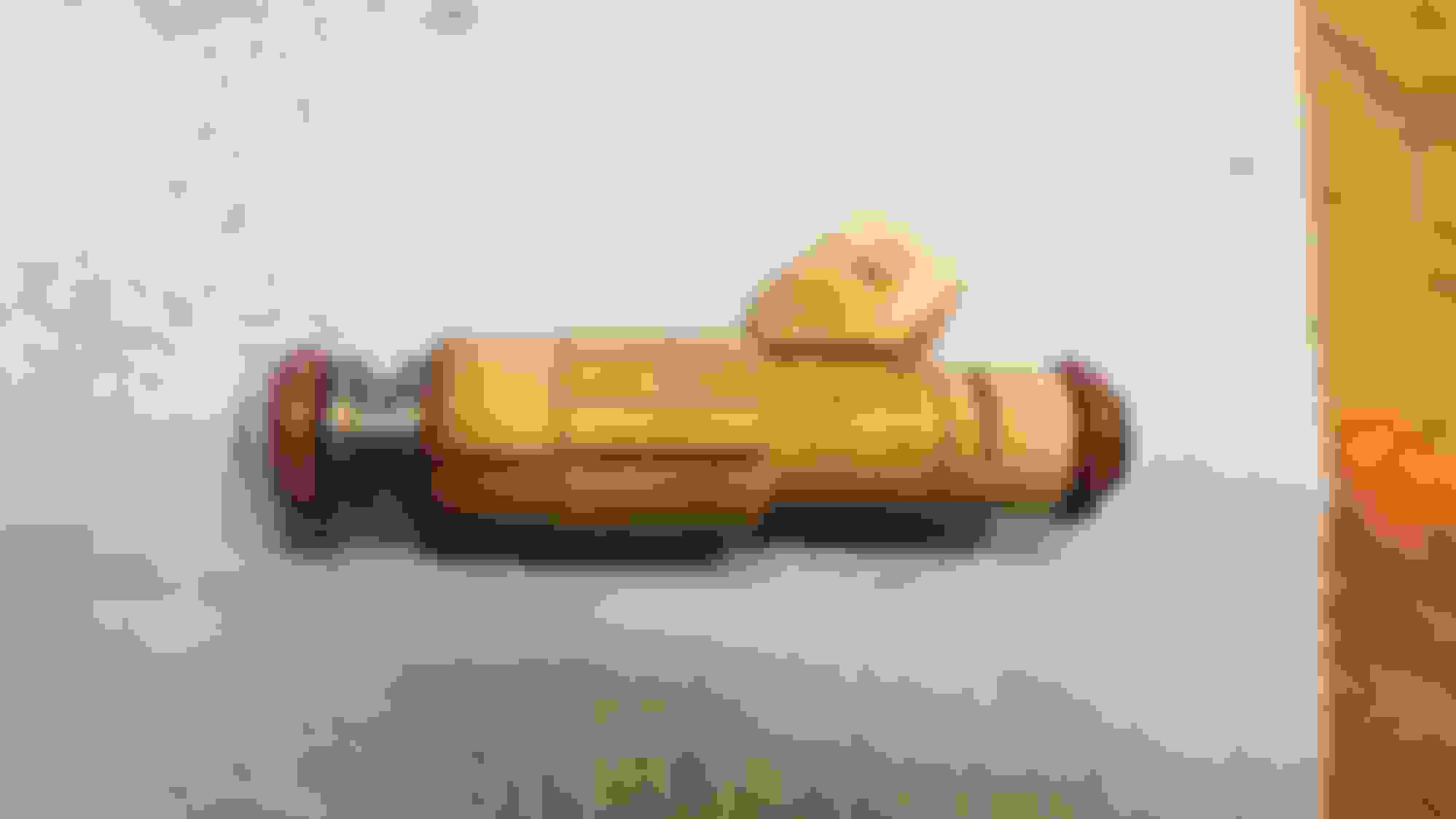
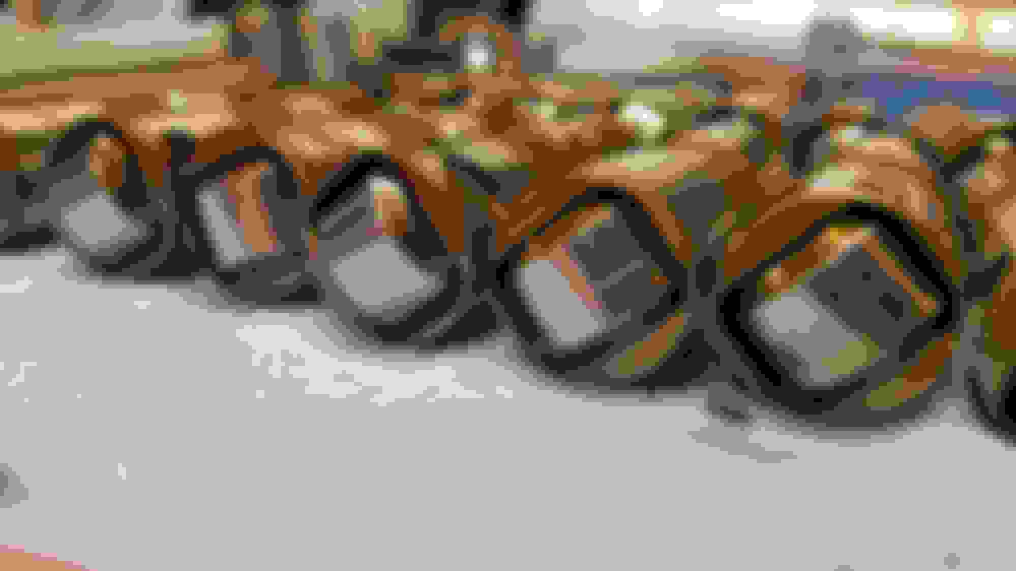
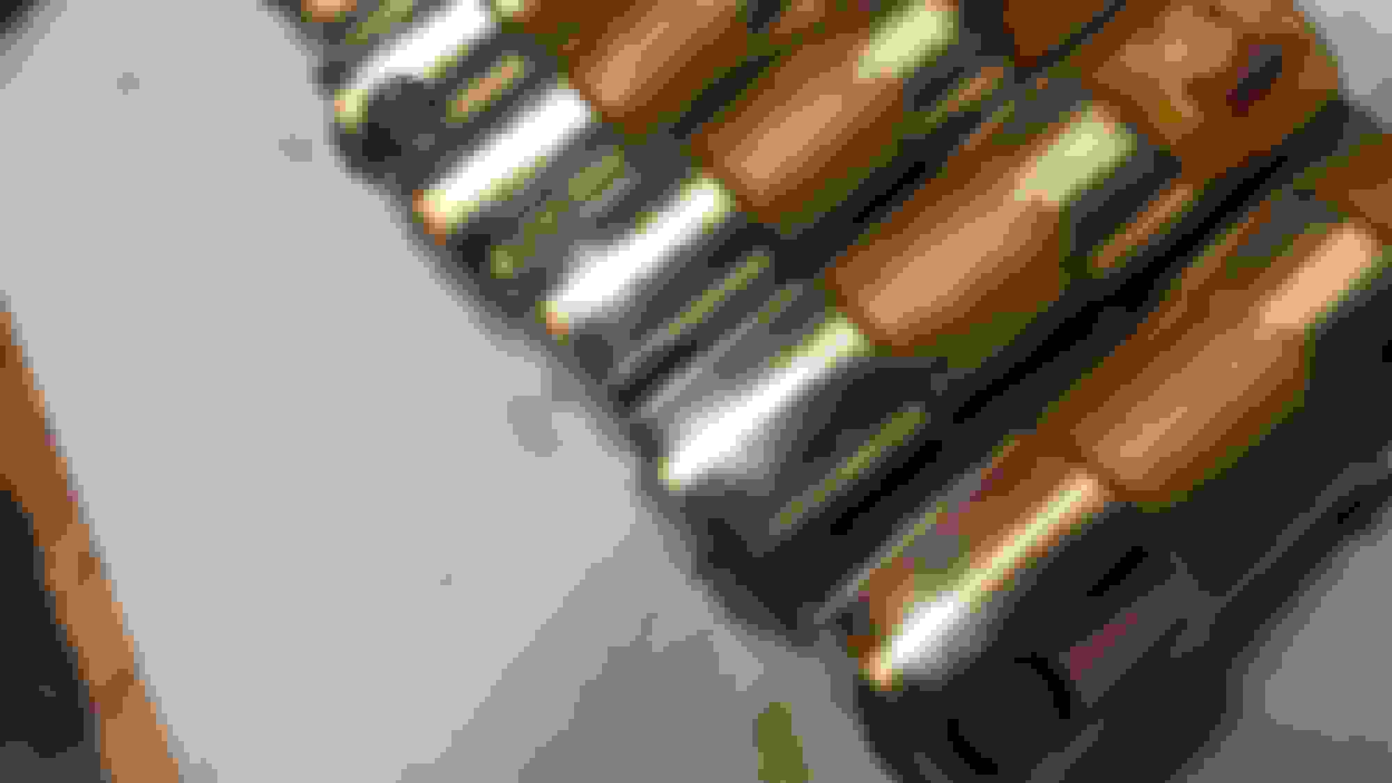
The forums keeps eating my words when I add pics, so going to keep the rest short. Here are the new injectors I'm using to support the fuel needed by the power mods. These are 36lb Bosch injectors, to replace the 26 or so lb. injectors. They drop right into the same fuel rail, and harness connections.
Old injectors are in good shape, only used for a few thousand miles, had them serviced before using, and will be for sale once I confirm all is well with the new ones.
Filled up the engine with the break in oil I bought. Will do the break in cycle and then drain this, change the filter and put in my usual Mobil1 5w-30
I will need to pick up some coolant to finish filling the system, and also a quart of power steering fluid.
As I finished my night I found these - the motor mount heat shields. Guess I forgot to install them, and I'm not sure how easy that will be at this point. Might just leave them off, since at least one is looking pretty ratty from me trying to make it fit. I may just use some heat shield fabric material I have to give them some protection. They are poly mounts so I'm not sure if they are more resistant to heat than a stock mount. The headers are wrapped too. Guess I had to forget something.

 02-27-2019, 03:28 PM


 So once I received the gun
I was able to bond the gussets to the car. The adhesive can take up to 7 days to fully cure, but I waited about 3 days before I started back working on the mounts. The epoxy seemed very hard by this point and very strong. I decided to go with some larger angle iron, but also to shorten it a bit so it would only be as long as the distance between the two gussets, and a few inches past on either side. you are supposed to clamp the piece tightly for a few hours, but I couldn't do that so I used some self-tapping screws to attach the gusset tightly while it cures, and just left them in. The adhesive also provides a water tight seal.
So once I received the gun
I was able to bond the gussets to the car. The adhesive can take up to 7 days to fully cure, but I waited about 3 days before I started back working on the mounts. The epoxy seemed very hard by this point and very strong. I decided to go with some larger angle iron, but also to shorten it a bit so it would only be as long as the distance between the two gussets, and a few inches past on either side. you are supposed to clamp the piece tightly for a few hours, but I couldn't do that so I used some self-tapping screws to attach the gusset tightly while it cures, and just left them in. The adhesive also provides a water tight seal.


 Though I'll be elated once I have it all running as I've been hoping.