pj_mcgarvey's - LS1/T56 NB build thread

 11-22-2016, 03:41 PM
#76
V8 Miata Enthusiast
Thread Starter

I have a tracking number on my driveshaft, and some fuel system parts I need.
Other than that I won't be making much progress over the next few days as I'm having some lower back pain that will keep me out of the garage for a few days. Great time to take a breather and enjoy the upcoming holiday week. Weather is dipping down into the 40s lately making it a bit harder to get into the garage.
Some updates from the last week
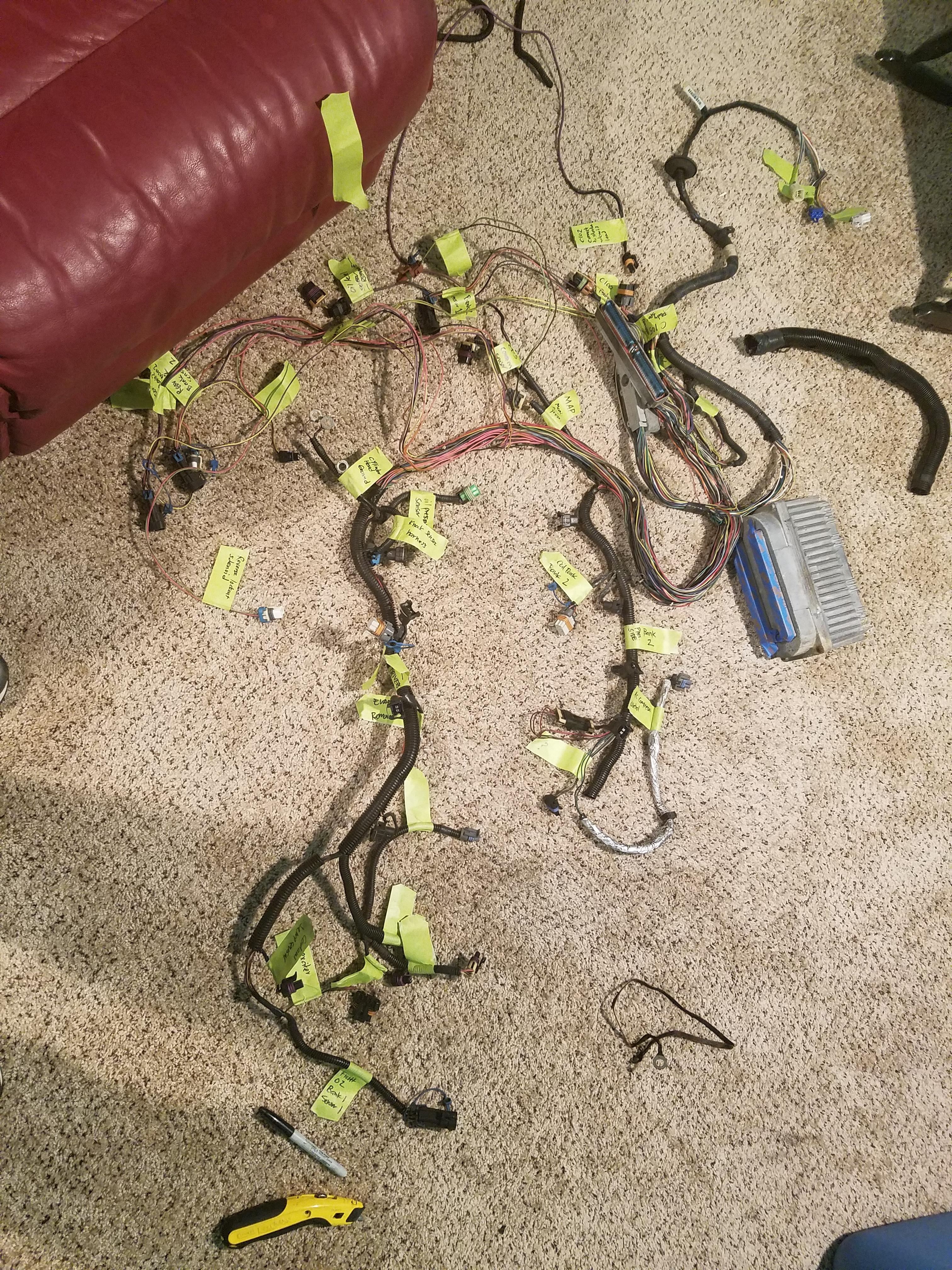
Started picking apart the LS1 harness. I've ID'd all of the connectors, have a good idea of what I need to remove, I have the reflashed PCM, so I'm in a good spot here. I'll post some links and info on the wiring stuff as I wrap my head around it some more
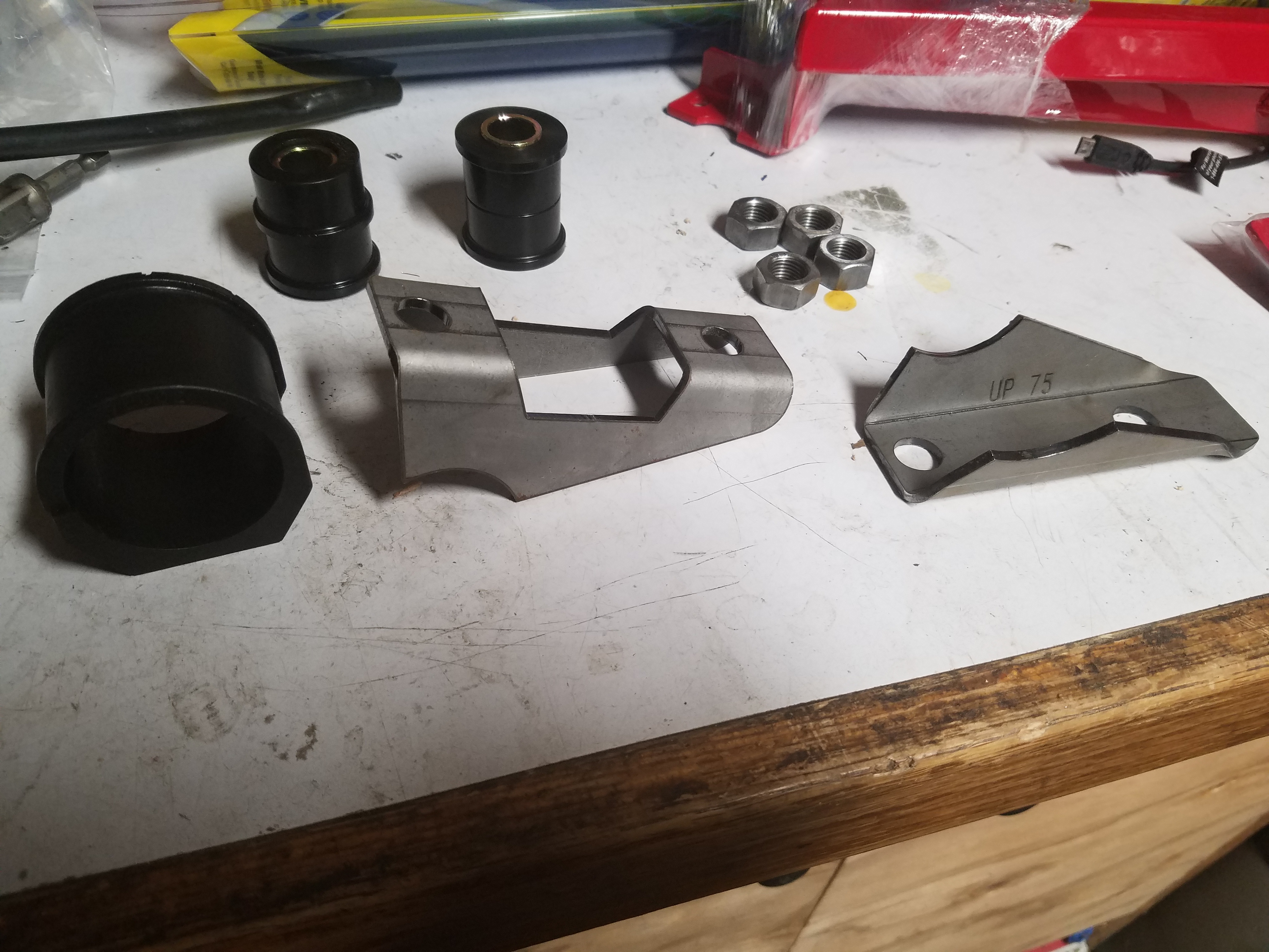
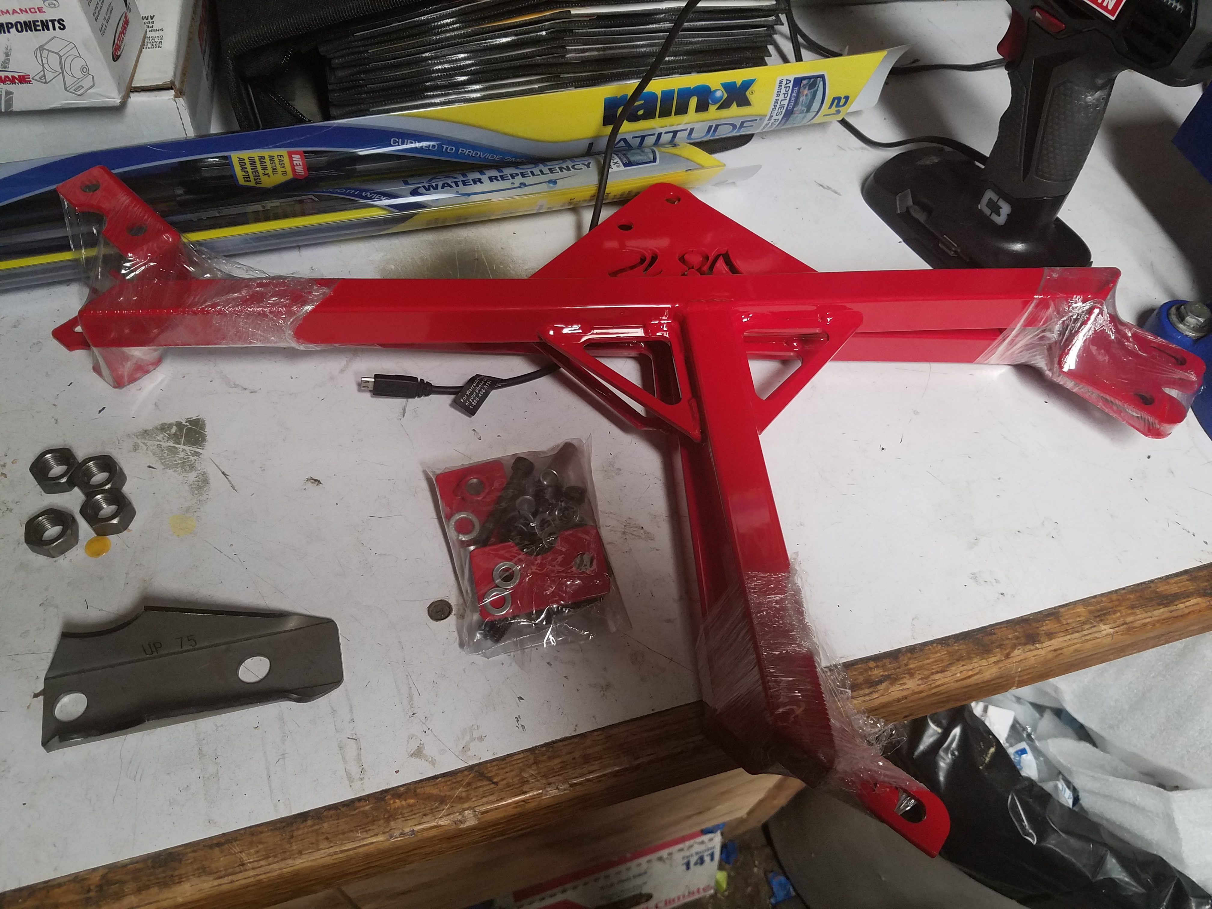
To solve my steering rack mount issue (I found out I have an NA subframe mount, not NB) it occurred to me to give V8 Roadsters a call for the brackets I need. They hooked me up. While browsing their site I also pulled the trigger on their cross braces once I realized how light they are (3 pound for both) and how much work it might be making my own (my original plan).
I also ordered up some poly rack bushings from Energy Suspension
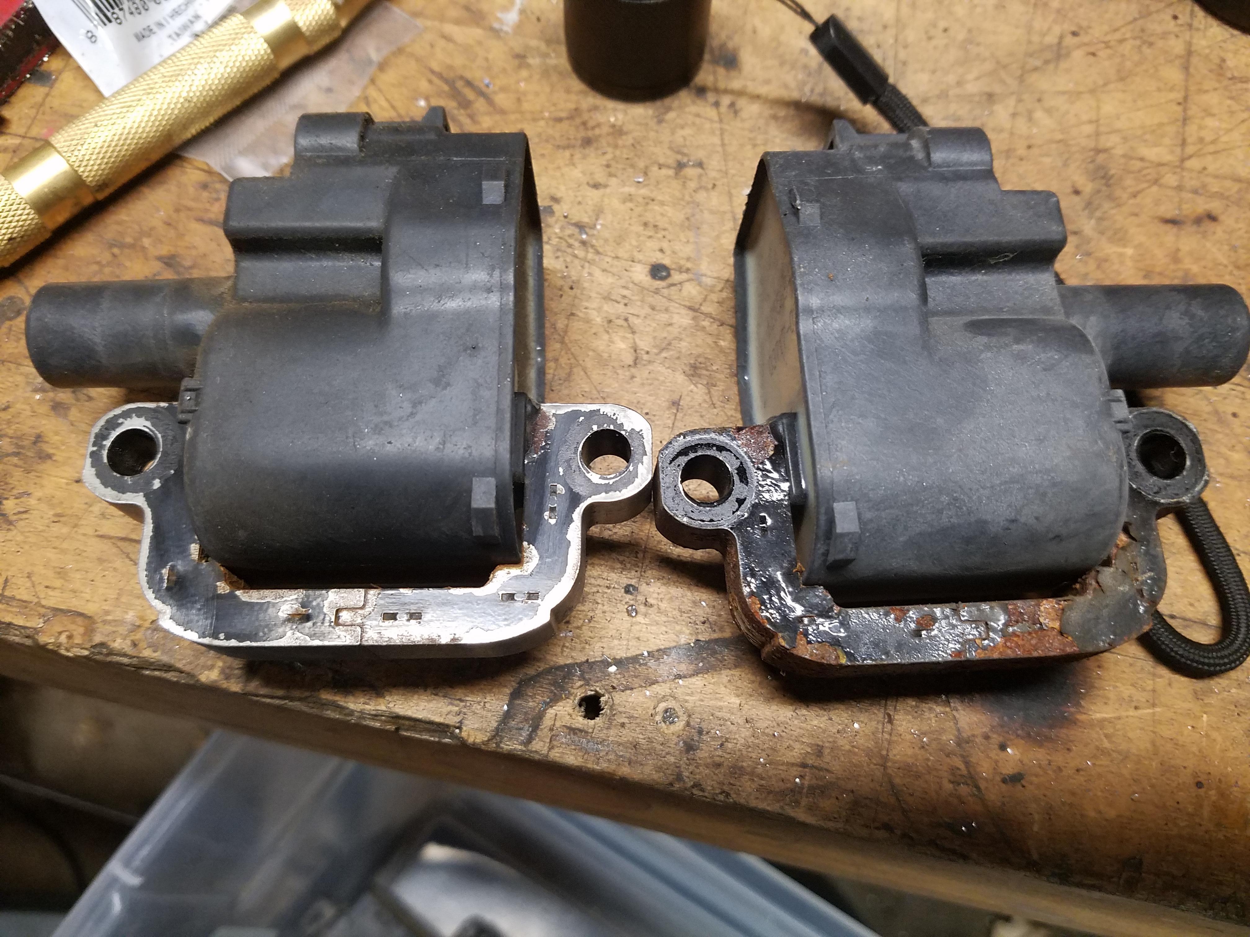
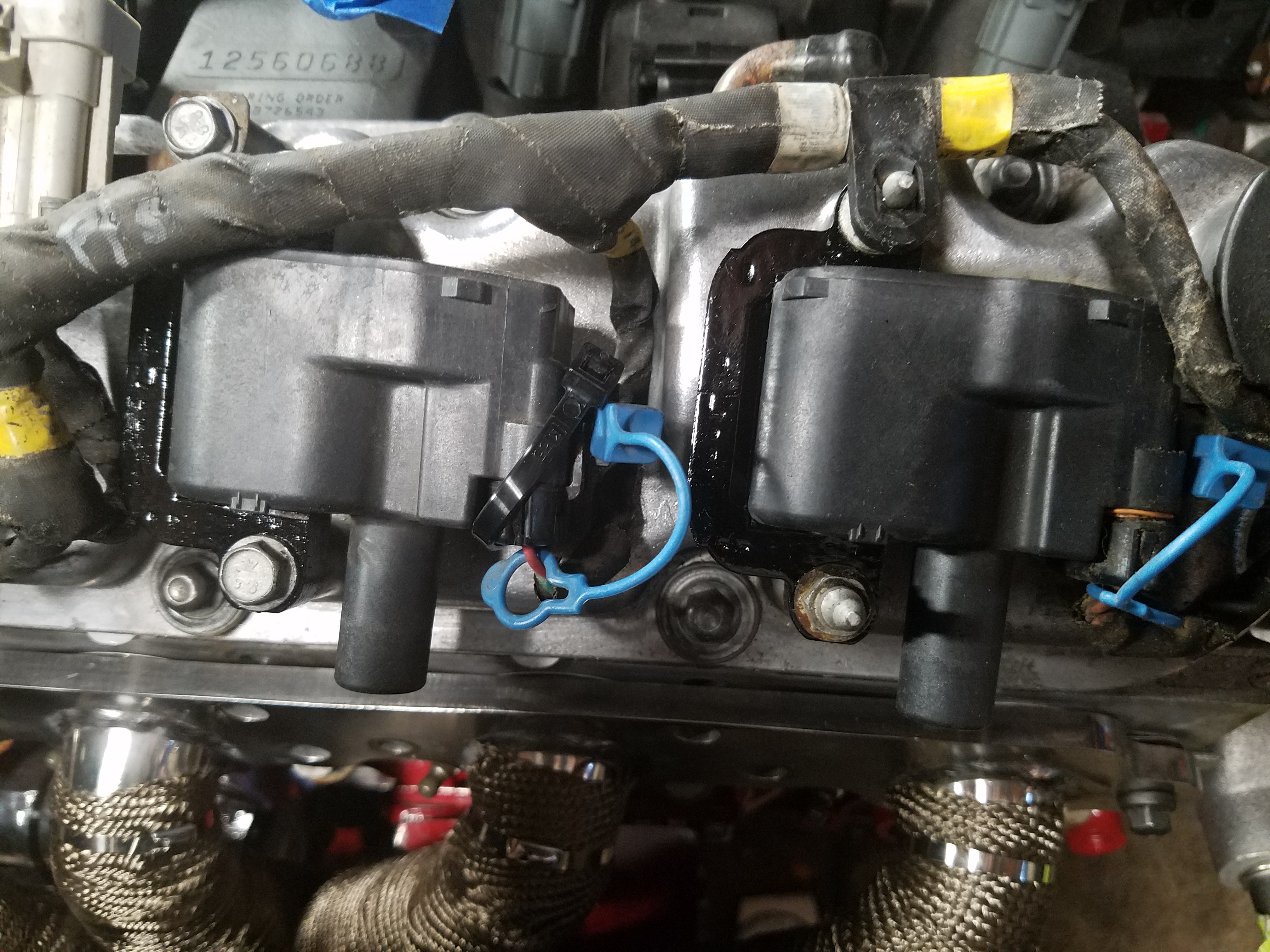
Decided to clean up the rusty/flaky coil pack brackets. Hit it with the wire wheel and then brushed on some rust preventer stuff I had laying around. Rusty on the right, wire wheeled on the left.
Repainted
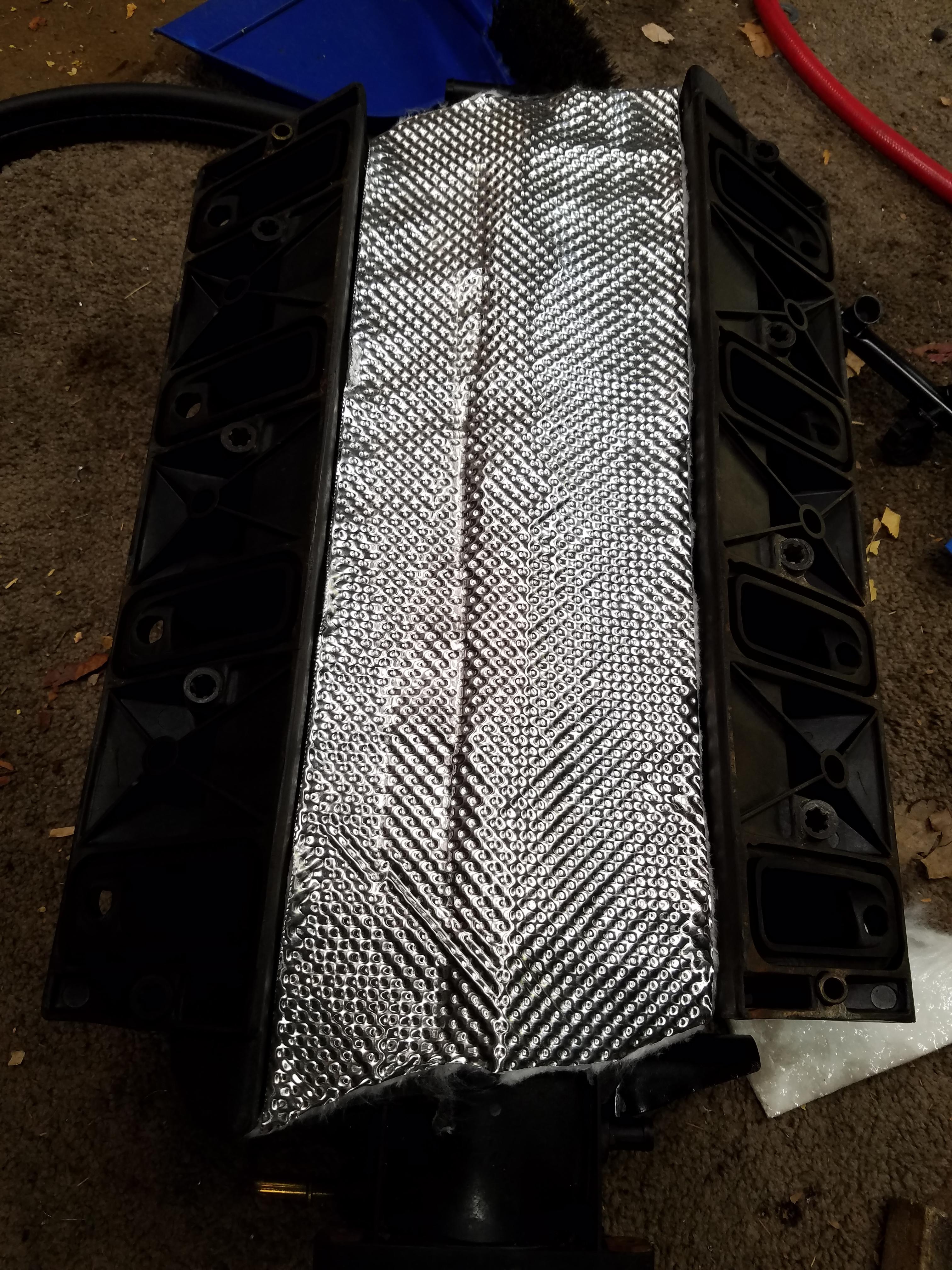
In an effort to try to heat shield the intake using a product I saw being sold online (for way more than I'd pay) I tried this
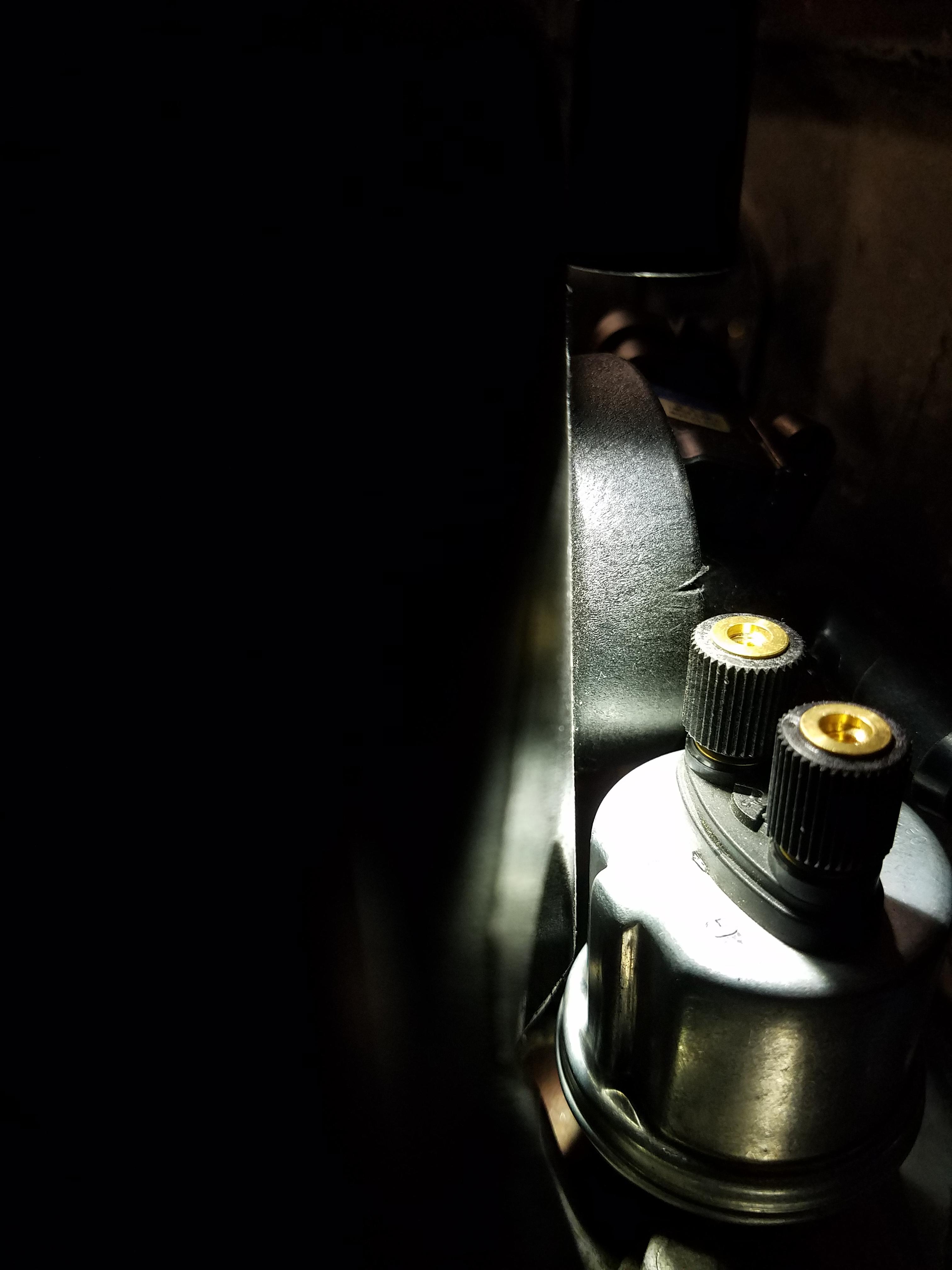
My VDO oil pressure sender with warning light function that I had been using on the Miata engine was installed, but it was a VERY tight fit.
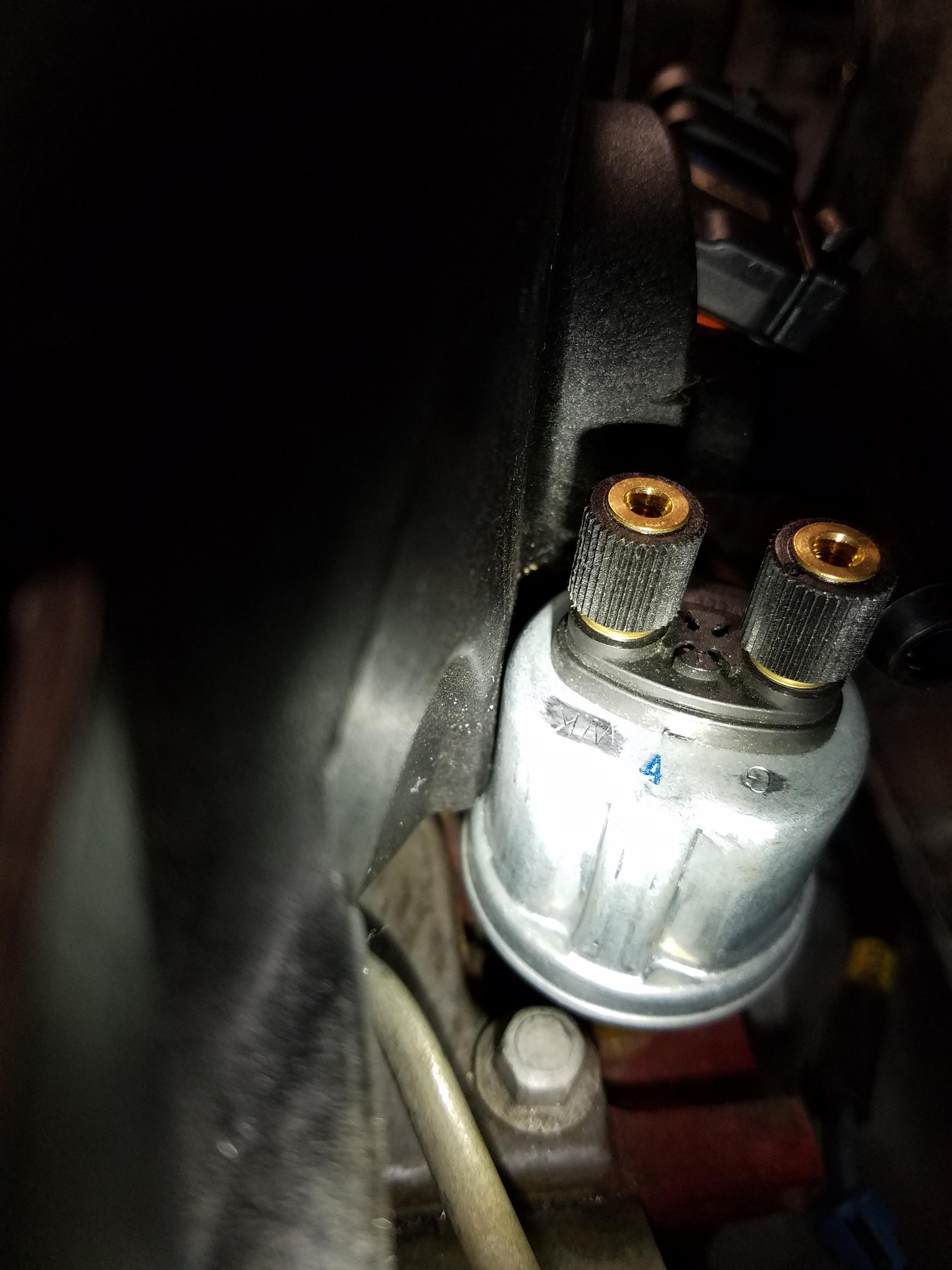
Not comfortable with this, so I used my die grander to remove a bit of plastic, just enough to give an 1/8" of clearance. Not sure how much material is there, so play it safe
Sneak peek of the engine in the process of getting dressed.
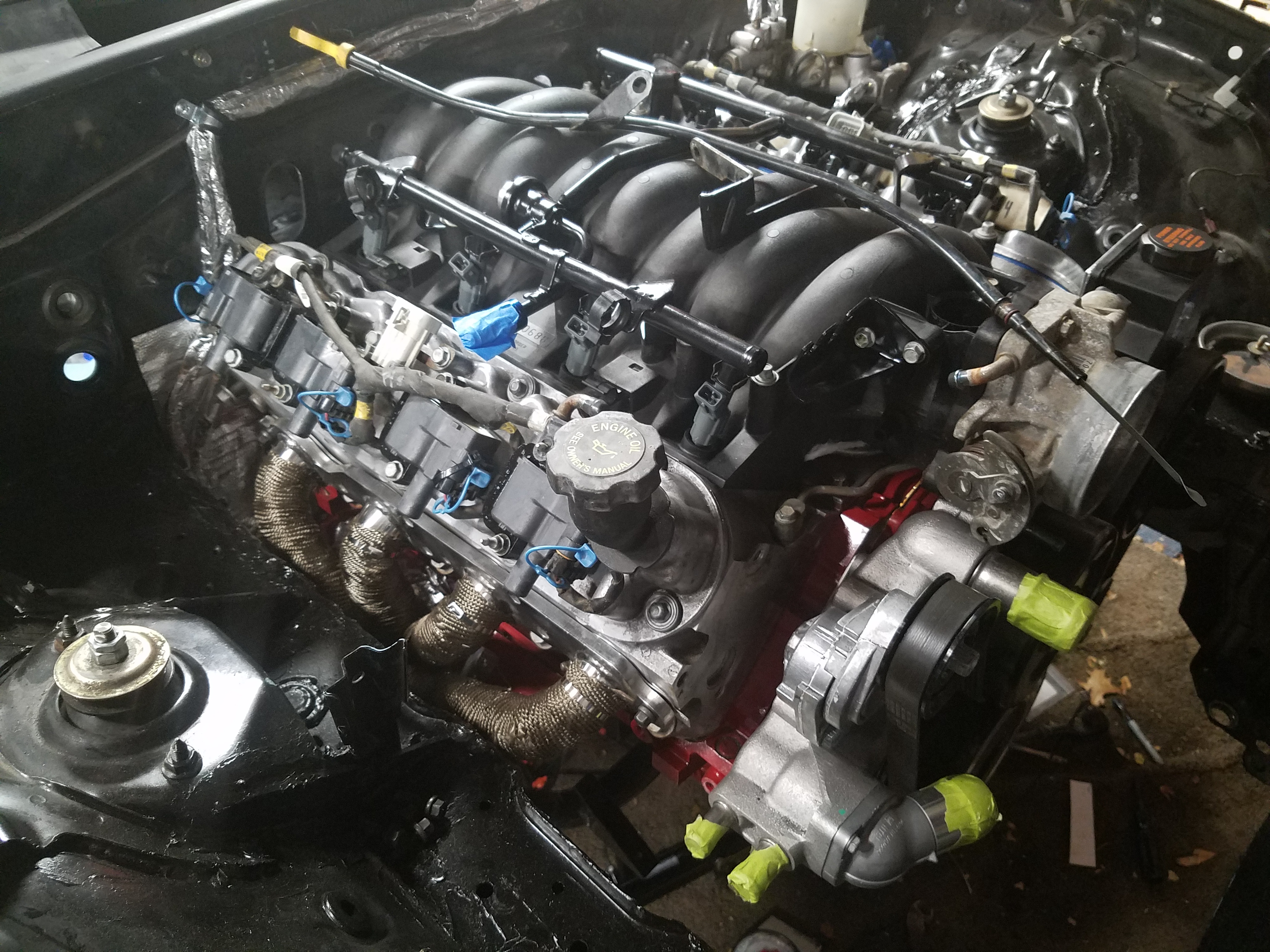
I had also repainted the fuel rail since it was also showing some wear. I had the fuel injectors cleaned and balanced by Marren Fuel Injection (www.injector.com) back in April after I picked up the motor.
Other than that I won't be making much progress over the next few days as I'm having some lower back pain that will keep me out of the garage for a few days. Great time to take a breather and enjoy the upcoming holiday week. Weather is dipping down into the 40s lately making it a bit harder to get into the garage.
Some updates from the last week
Started picking apart the LS1 harness. I've ID'd all of the connectors, have a good idea of what I need to remove, I have the reflashed PCM, so I'm in a good spot here. I'll post some links and info on the wiring stuff as I wrap my head around it some more
To solve my steering rack mount issue (I found out I have an NA subframe mount, not NB) it occurred to me to give V8 Roadsters a call for the brackets I need. They hooked me up. While browsing their site I also pulled the trigger on their cross braces once I realized how light they are (3 pound for both) and how much work it might be making my own (my original plan).
I also ordered up some poly rack bushings from Energy Suspension
Decided to clean up the rusty/flaky coil pack brackets. Hit it with the wire wheel and then brushed on some rust preventer stuff I had laying around. Rusty on the right, wire wheeled on the left.
Repainted
In an effort to try to heat shield the intake using a product I saw being sold online (for way more than I'd pay) I tried this
My VDO oil pressure sender with warning light function that I had been using on the Miata engine was installed, but it was a VERY tight fit.
Not comfortable with this, so I used my die grander to remove a bit of plastic, just enough to give an 1/8" of clearance. Not sure how much material is there, so play it safe
Sneak peek of the engine in the process of getting dressed.
I had also repainted the fuel rail since it was also showing some wear. I had the fuel injectors cleaned and balanced by Marren Fuel Injection (www.injector.com) back in April after I picked up the motor.
 11-22-2016, 03:56 PM
#77
V8 Miata Enthusiast
Thread Starter
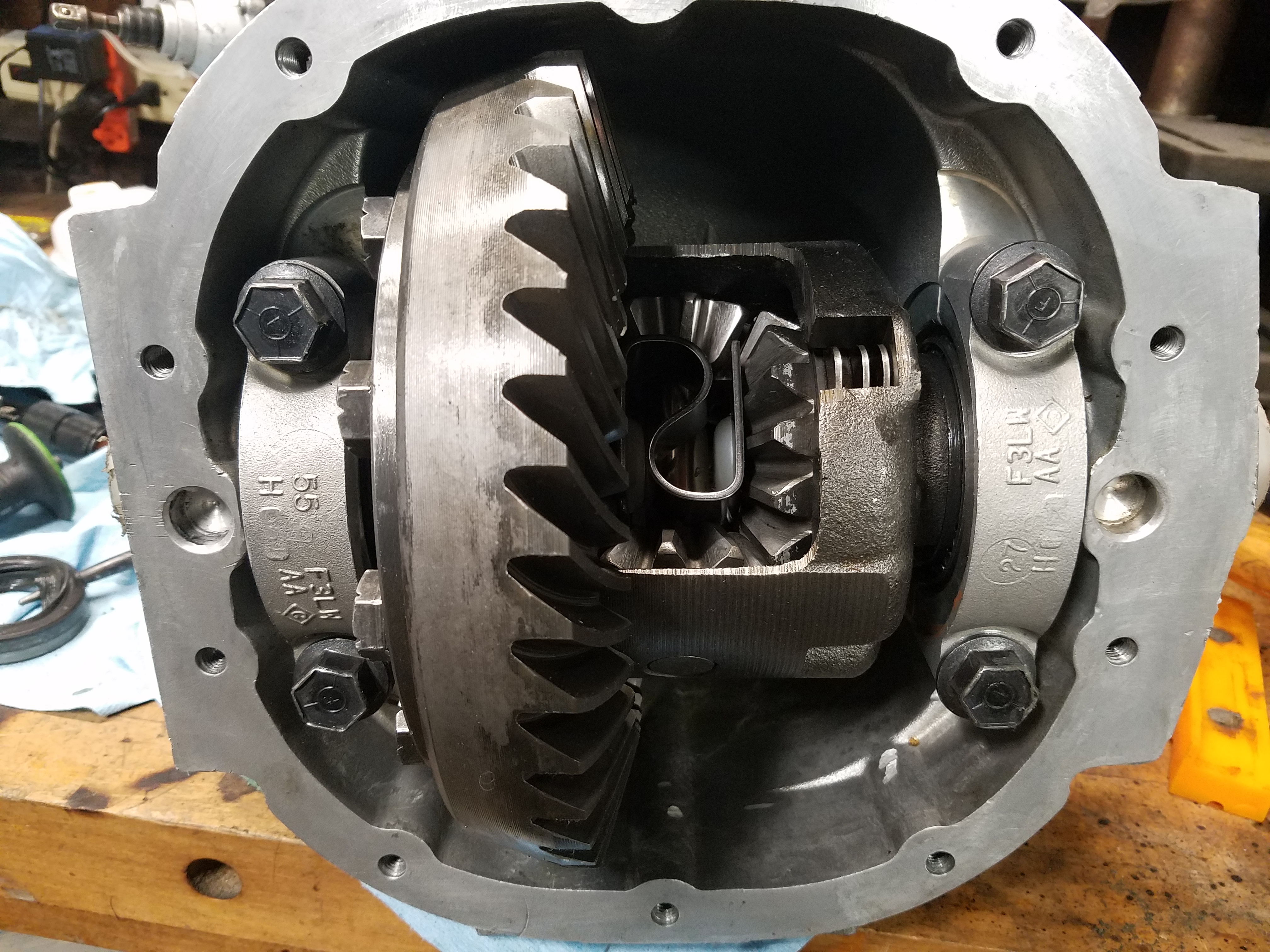
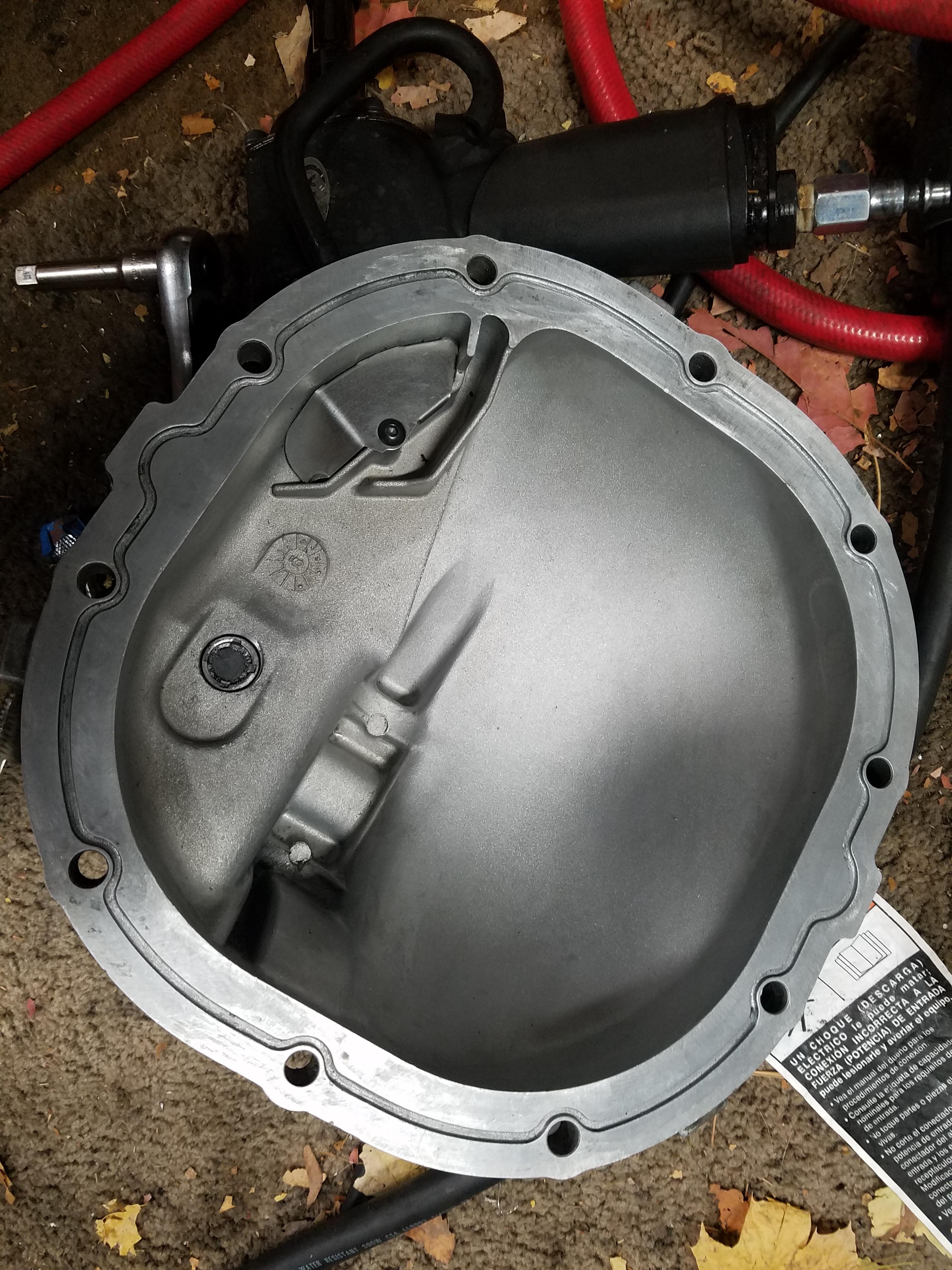
While I wait for the driveshaft, I decided to give the Ford 8.8" diff a once over. It was missing a diff cover bolt, and it looked like the cover was sealed with silicone caulk, which the Ford rebuild instructions specifically say not to use...
Opened up the diff to have a look
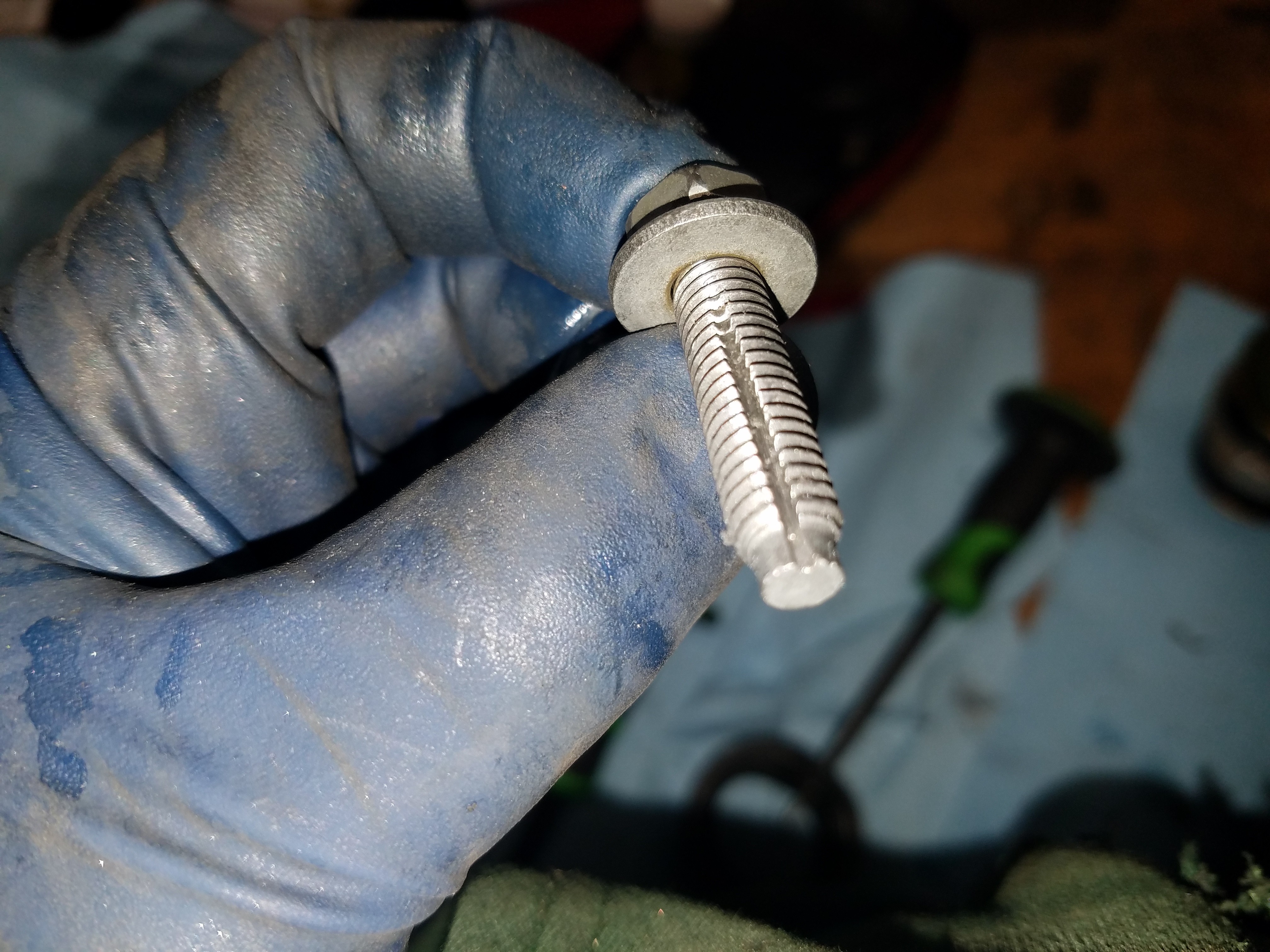
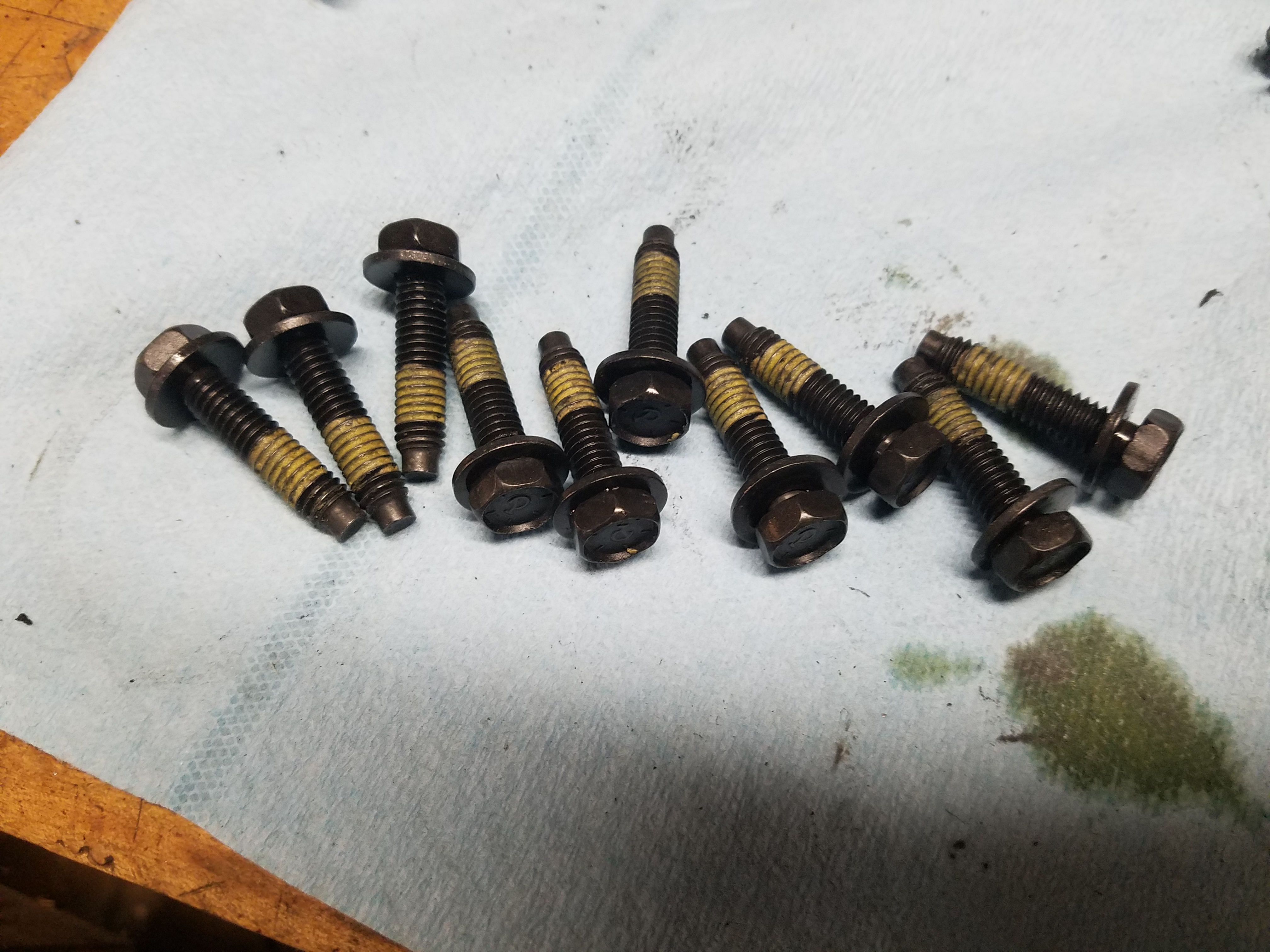
Cut a slit down one of the old bolts to make my own thread chaser as some silicone (mix of black, probably RTV, and clear silicone was in the bolt holes) to clean it up
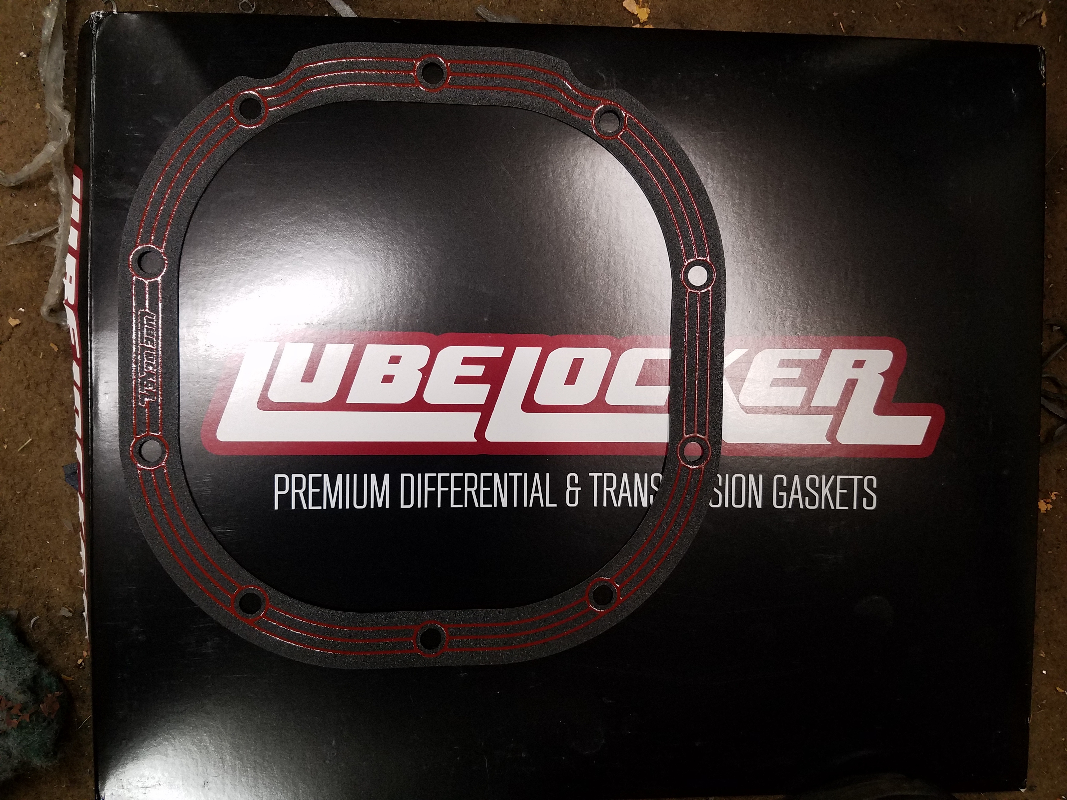
Thought I'd give one of these LubeLocker gaskets a try. Reviews seemed to be good on them https://www.amazon.com/gp/product/B008RAFJ38
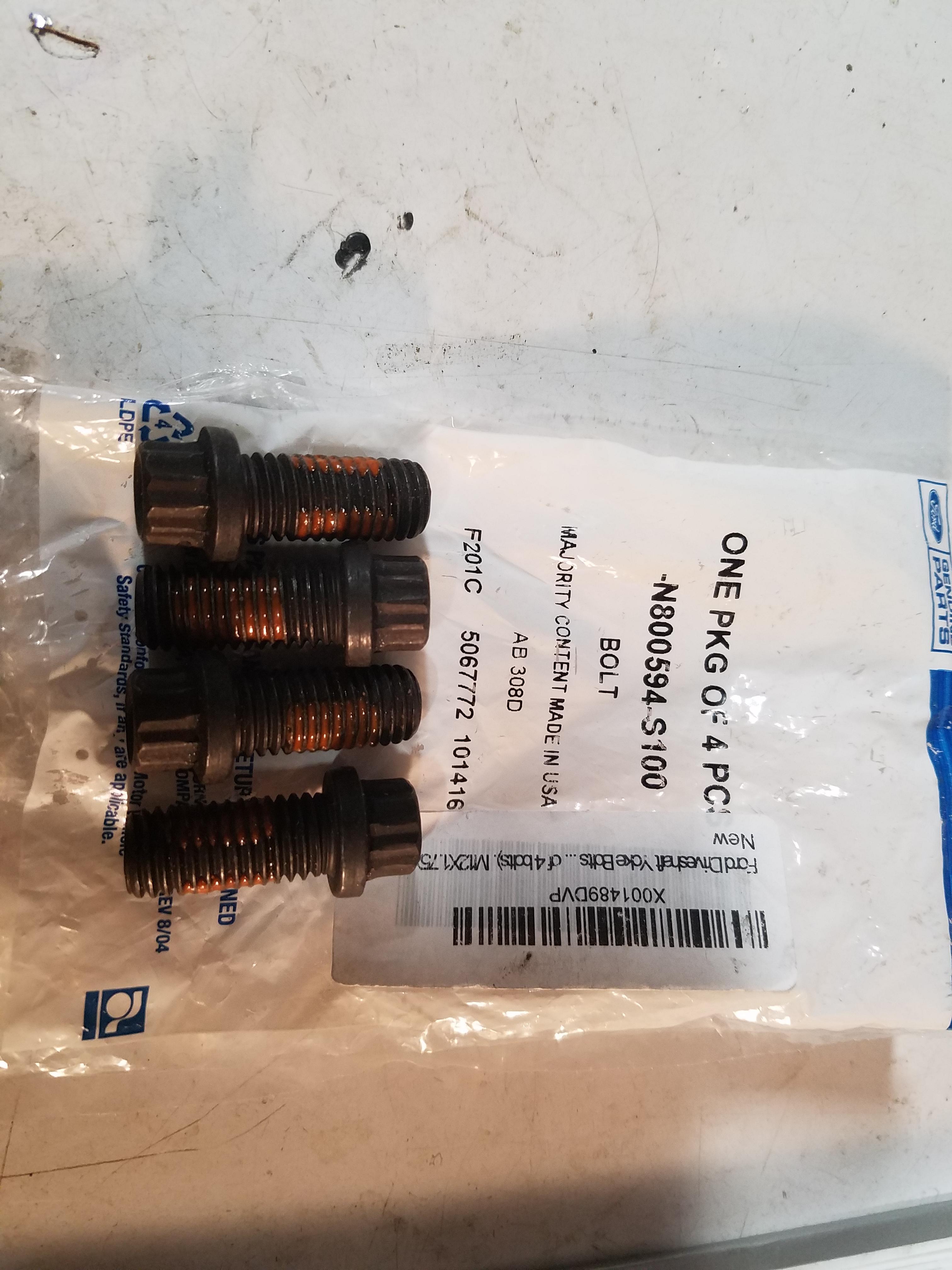
New OEM bolts
Cleaned up the cover real nice. comes with a magnetic fill plug, had some shavings on it...
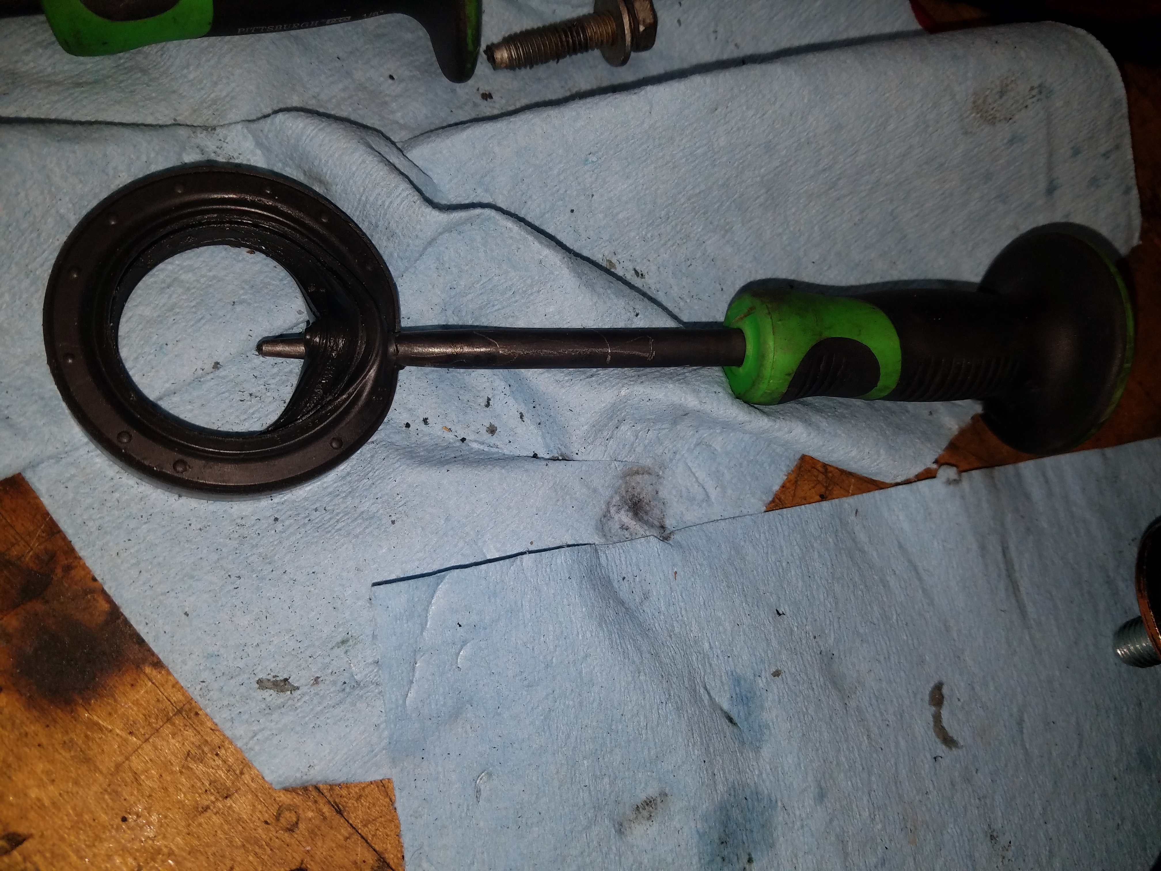
Also replaced the axle seals, you won't know these are leaky until everything is installed and you take it for a drive. Cheap insurance. The prices that Rock Auto had on this were WAY cheaper than I was seeing elsewhere. $6 each for Timken seals, plus a few bucks for shipping. 1999 FORD MUSTANG 4.6L V8 DOHC Axle Shaft Seal | RockAuto
Also picked up a new VBelt - https://www.amazon.com/gp/product/B000C2WKRM
New engine coolant sensor - https://www.amazon.com/gp/product/B001W0FSMM
Opened up the diff to have a look
Cut a slit down one of the old bolts to make my own thread chaser as some silicone (mix of black, probably RTV, and clear silicone was in the bolt holes) to clean it up
Thought I'd give one of these LubeLocker gaskets a try. Reviews seemed to be good on them https://www.amazon.com/gp/product/B008RAFJ38
New OEM bolts
Cleaned up the cover real nice. comes with a magnetic fill plug, had some shavings on it...
Also replaced the axle seals, you won't know these are leaky until everything is installed and you take it for a drive. Cheap insurance. The prices that Rock Auto had on this were WAY cheaper than I was seeing elsewhere. $6 each for Timken seals, plus a few bucks for shipping. 1999 FORD MUSTANG 4.6L V8 DOHC Axle Shaft Seal | RockAuto
Also picked up a new VBelt - https://www.amazon.com/gp/product/B000C2WKRM
New engine coolant sensor - https://www.amazon.com/gp/product/B001W0FSMM
Last edited by pj_mcgarvey; 11-25-2016 at 12:27 PM.
11-22-2016, 04:02 PM
#78
V8 Miata Enthusiast
Thread Starter
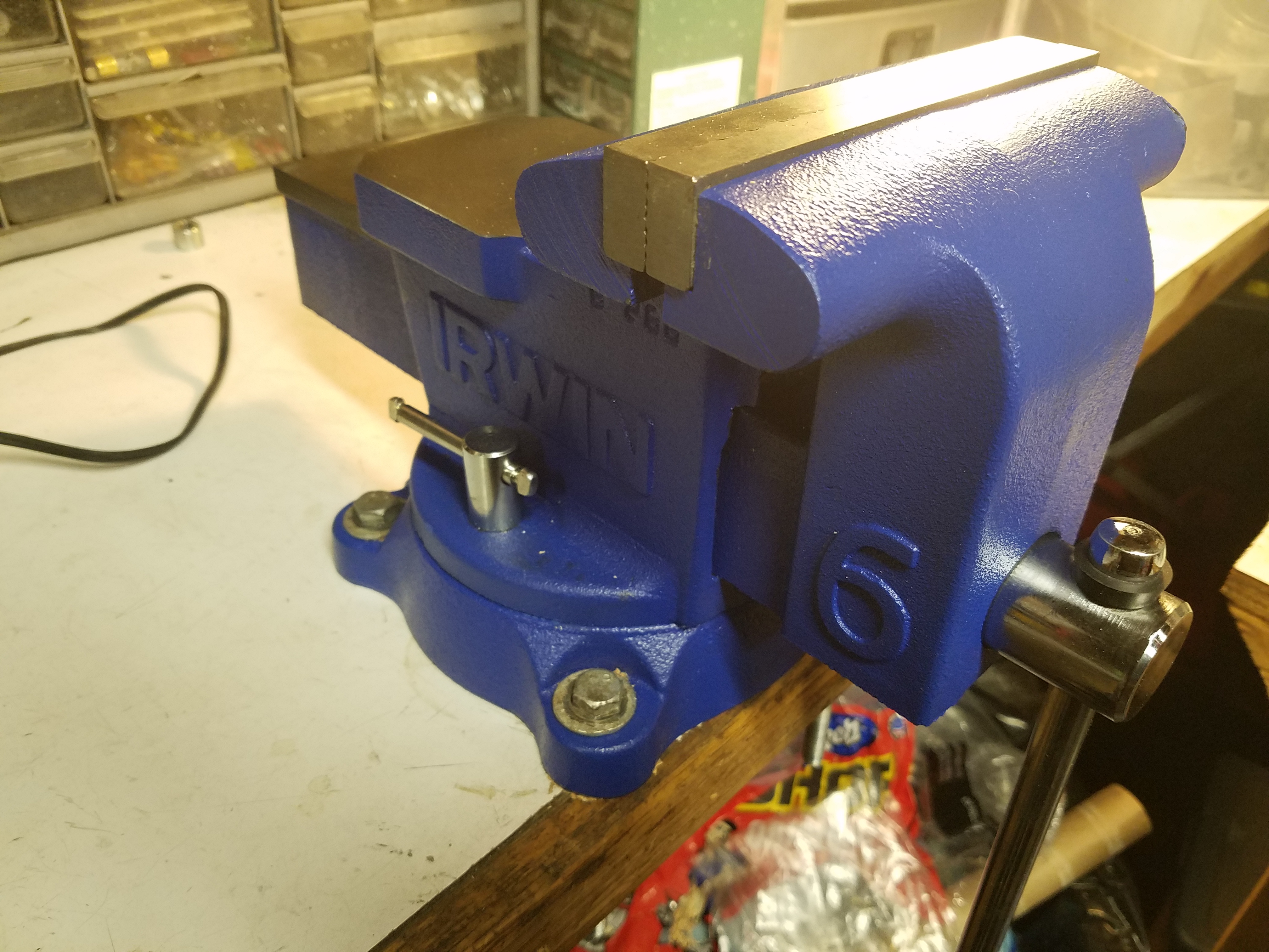
Shout out to my new vice. https://www.amazon.com/gp/product/B0001LQY3U
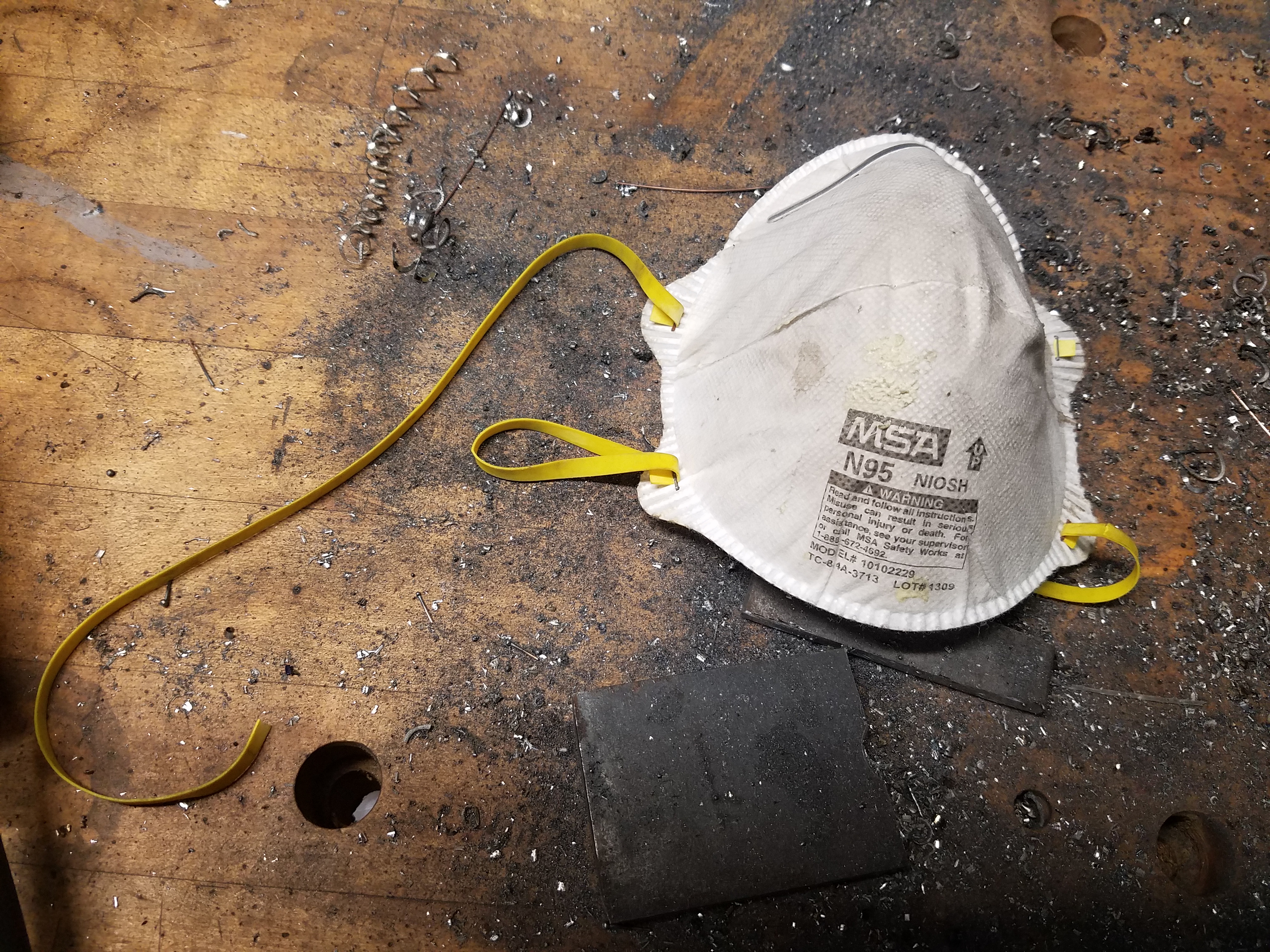
Also to these dust masks I bought a pack of at Home Depot. The filtration is better, and they are much more comfortable - noticably so. You are using a dust mask when cutting/grinding metal right?
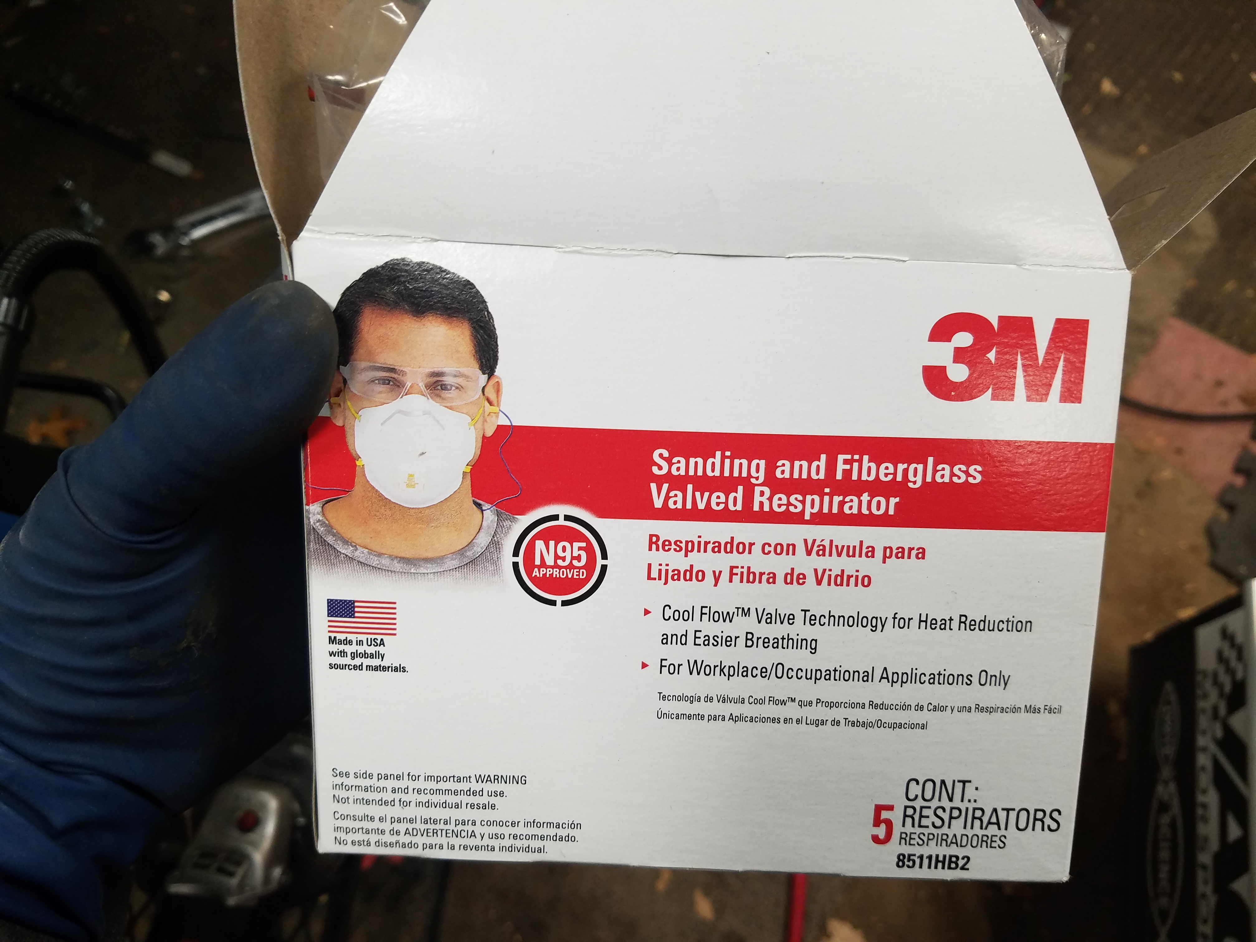
Big middle finger to the MSA brand, the stupid head bands snap after a few uses making them completely junk, and they aren't very comfortable grabbing at the hair on your head.
Also to these dust masks I bought a pack of at Home Depot. The filtration is better, and they are much more comfortable - noticably so. You are using a dust mask when cutting/grinding metal right?
Big middle finger to the MSA brand, the stupid head bands snap after a few uses making them completely junk, and they aren't very comfortable grabbing at the hair on your head.
Last edited by pj_mcgarvey; 12-14-2016 at 08:41 PM.
11-25-2016, 11:17 AM
#79
V8 Miata Zealot

Nice progress. FYI Ford has never used a gasket to seal the differential covers on anything that they have produced since the Ford 9inch. They ALL seal with RTV, mostly black, but the best being the grey diesel sealant.
12-08-2016, 08:14 AM
#80
V8 Miata Enthusiast
Thread Starter
Correct, the instructions say to use black RTV. The lubelocker seemed like a good idea, despite decades of using RTV. One advantage I could see is that you could seal it up with the gasket and be on the road alot quicker than waiting for RTV to set. That's definitely not the scenario I'm in, but in any case we'll see how it works out.
12-08-2016, 08:45 AM
#81
V8 Miata Enthusiast
Thread Starter
On with the build. Got the fuel system done. I will share some tips on how I like to do AN fittings.
I used the following fittings/hose from Racer Parts Wholesale. You could find the same stuff on Amazon I think but RPW was a good bit cheaper
AER-FBA0600-10 -6 Aeroquip Stainless Steel Braided Hose - -6 Aeroquip Stainless Steel Braided Hose, 10' section
AER-FCM4432 Aeroquip 90 Degree Reusable Elbow Fitting- Black Anodized - -06 Aeroquip 90 Degree Reusable Elbow Fitting- Black
AER-FCM4412 Aeroquip Straight Reusable Swivel Fitting- Black Anodized - -06 Aeroquip Straight Reusable Swivel Fitting- Black
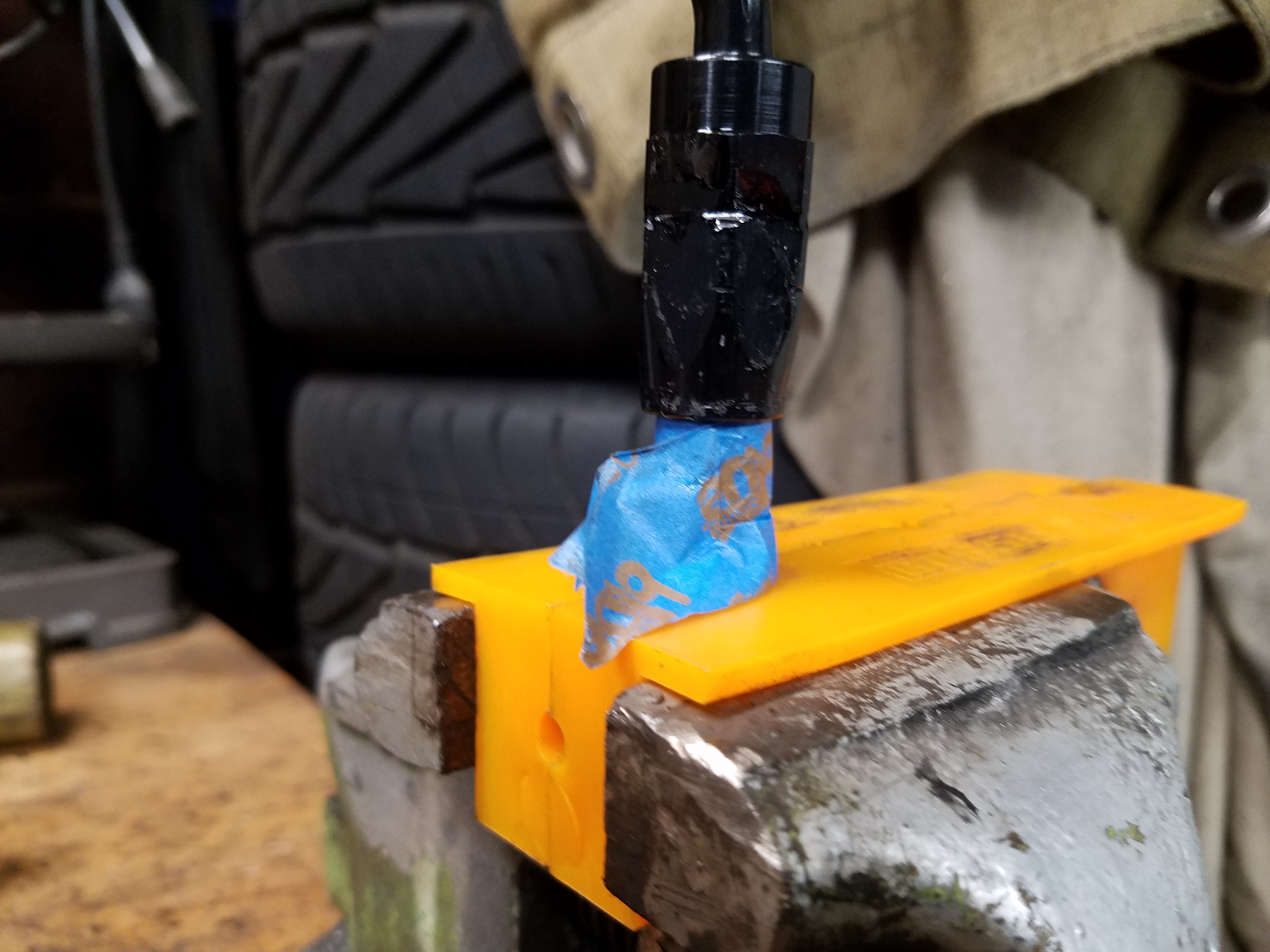
I clamp up the hose in some neat vice jaw holder that attach magnetically to the vice - not sure where I got them, but they have soft plastic jaws and they were handy in this case since they have a little slot for holding hose
I wrap the hose in electrical tape with a few tight wraps around. Then I use a metal cutting blade on my grinder, a thin one if possible, and make a cut around the hose. I try not to just cut the hose in one pass, but make about 4 cuts into the hose at around 90 degrees to each other. This prevents the braided material from fraying too much based on the way the blade cuts through it. Hope that makes sense.
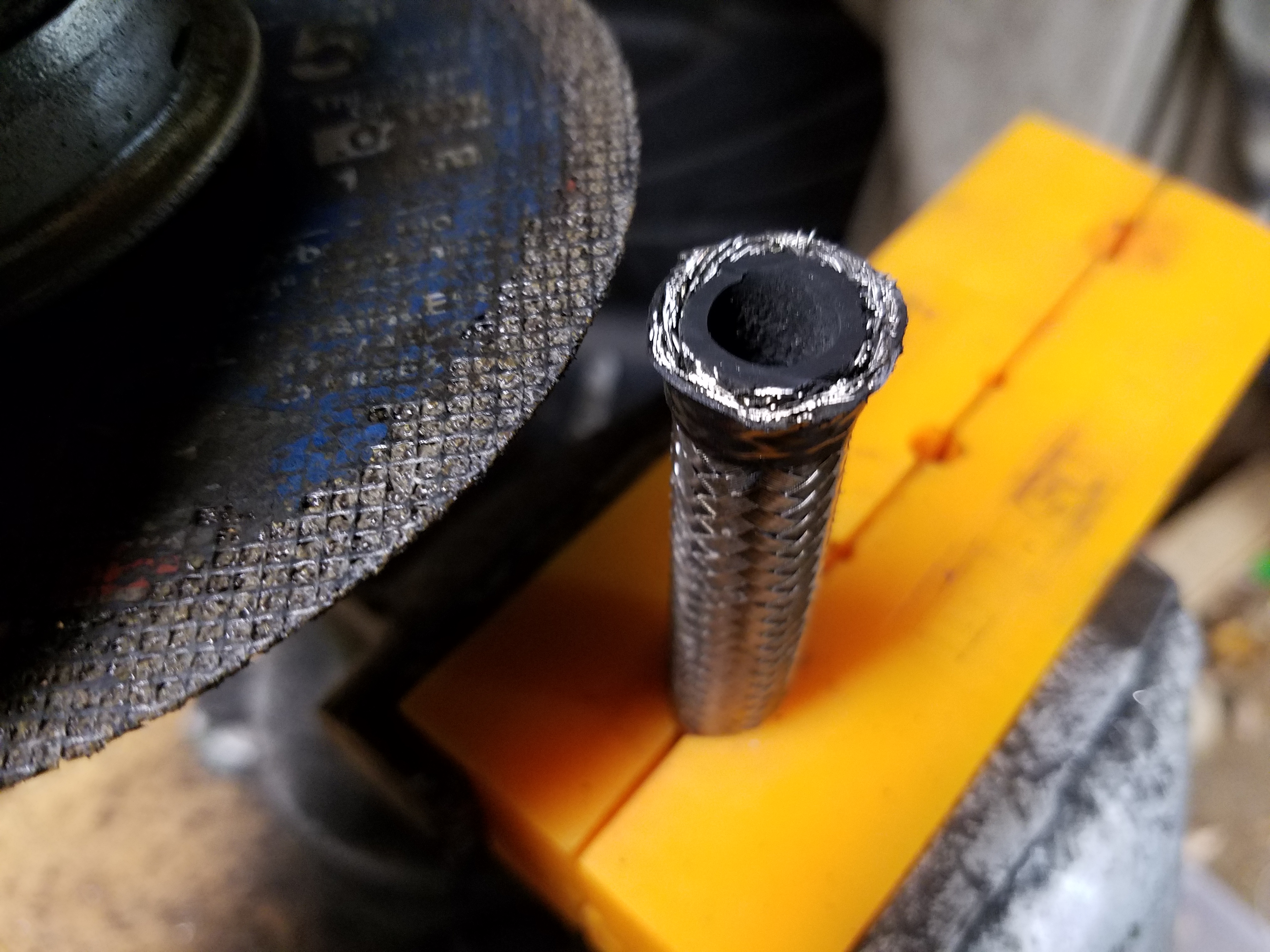
I use a small screwdriver to push in the frayed bits as I slide the hose end over. Just take your time and work around in a circular pattern. If you don't, the frayed ends will get more difficult to deal with and you may need to recut for a clean start. Seat the end down as far as it will go. Then I use a small screwdriver again to push in hose from the inside to get under the inside lip of the hose end. This will just make it easier to screw in the other piece of the hose end.
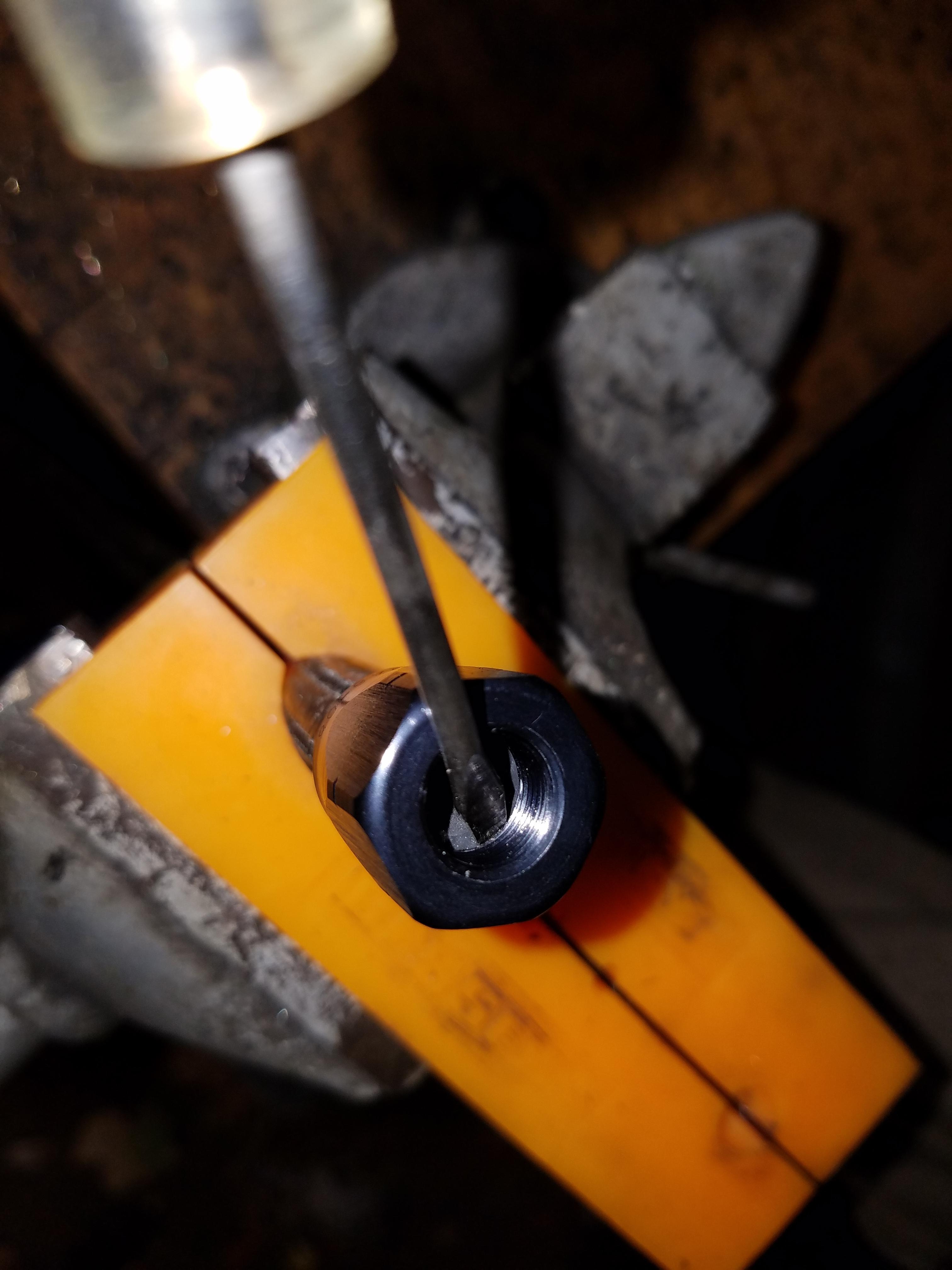
At this point I try to use an air gun to blow out some of the junk that will get caught in the threads, or possibly in the hose itself.
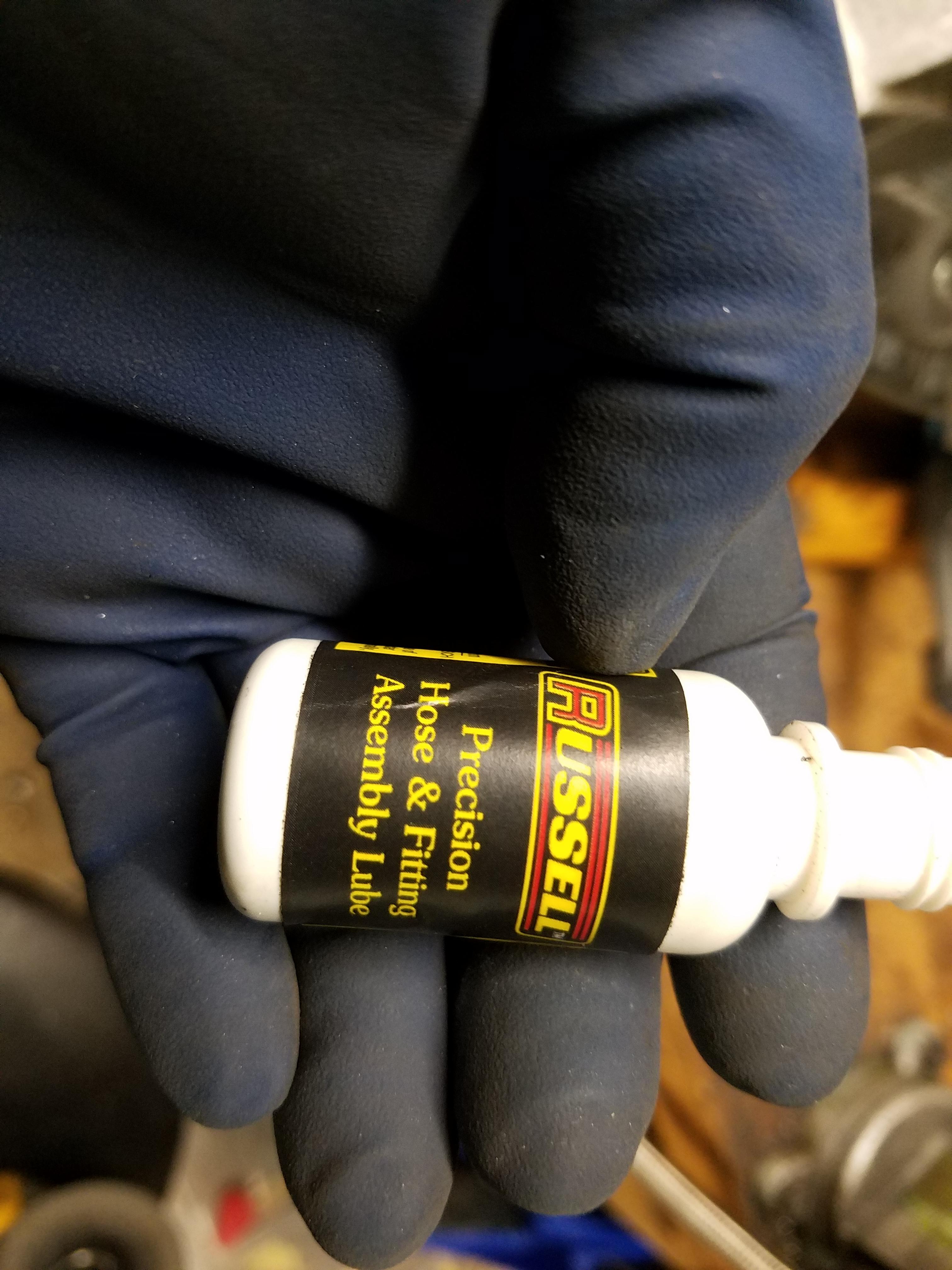
I use this lube on the threads and on the part that slides into the hose itself.
I also put a piece of tape on the hose where the bottom of the hose end stops. This let's me know if the hose end is pulling up as I tighten down the connection. If you use lube it's not usually a problem, but if you don't the friction of the connection can pull up the hose end away from the hose, and you won't have a good seal. Again, hope that makes sense.
Once all done, I took the hose into my basement utility sink and ran some hot water through it to flush out any debris. Used a small bottle brush for garage stuff and worked it into the hose where the new fitting is to clean out any junk.
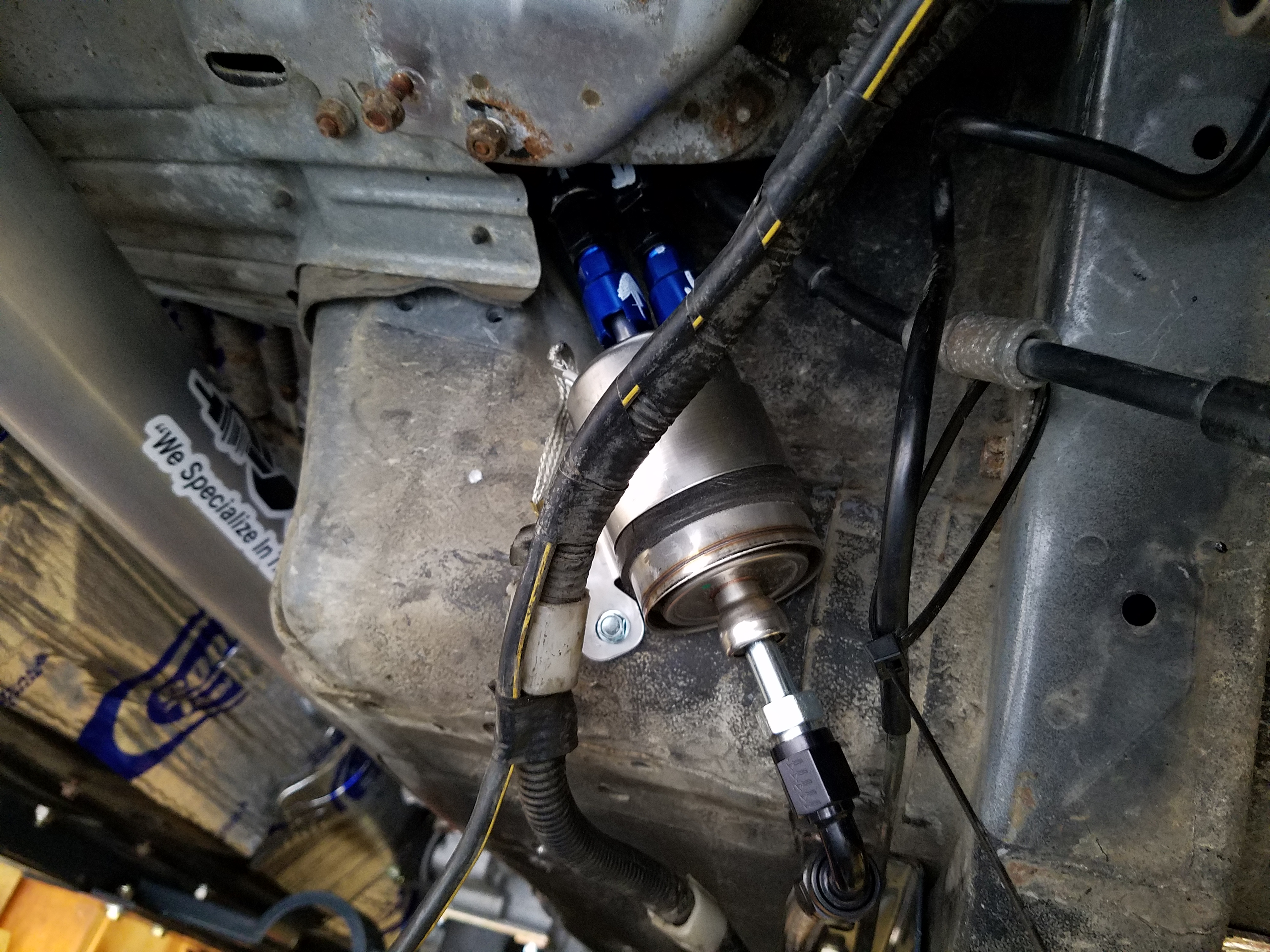
With one end done, I connect it to my fuel filter/reg and then bring it back up to the engine keeping it tight to the inside of the frame rails, and mark where my next cut will be.
My filter/reg mounted. A few tips on this, I thought it would be a bit easier to route the hose up to the top of the tank, but I ended dropping my already empty tank - it wasn't too hard at all. Just be aware of some connections near the back of the tank that might get caught up. You just need to drop it enough to see where you are doing with the hose and get the length right.
Final connection with the fuel rail
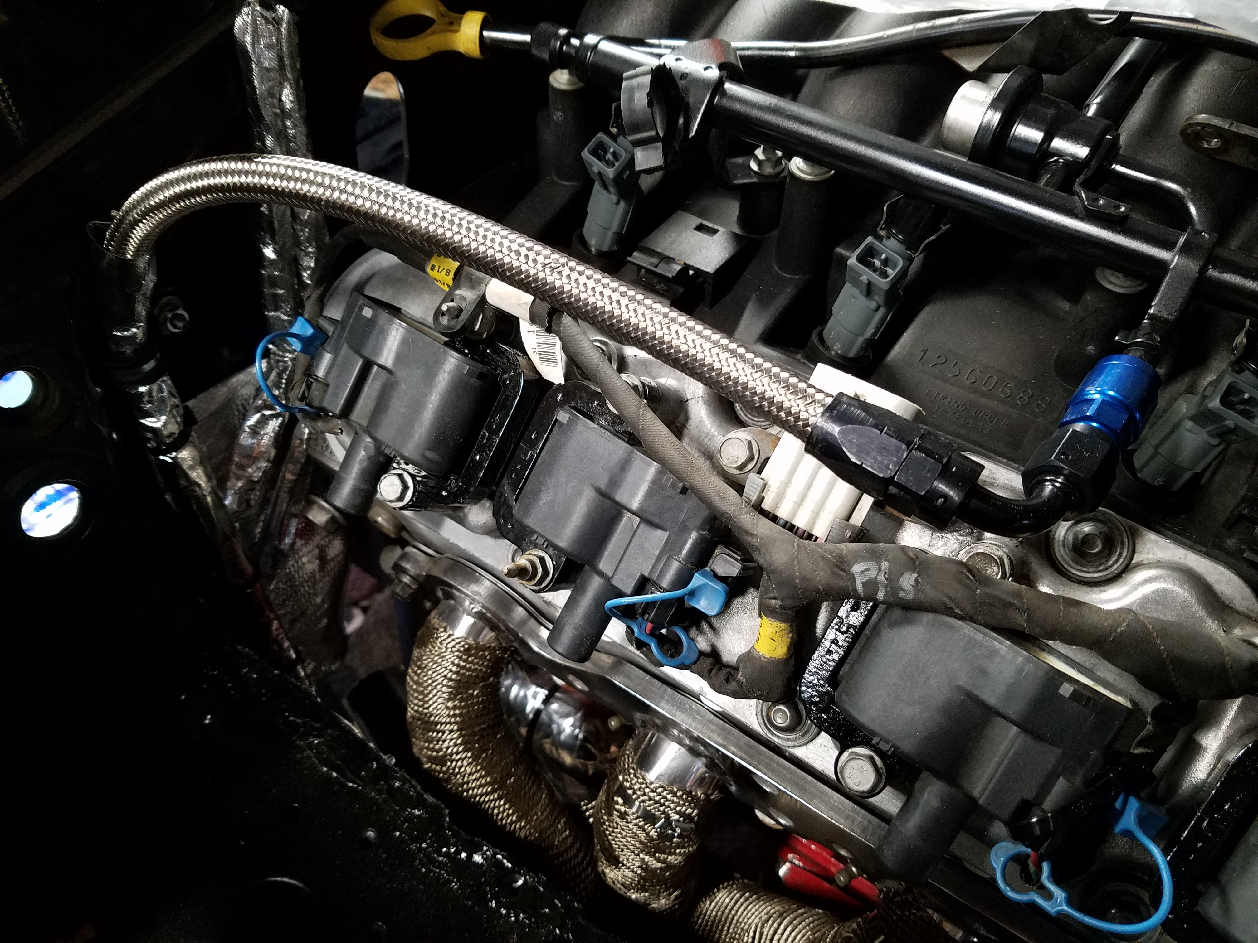
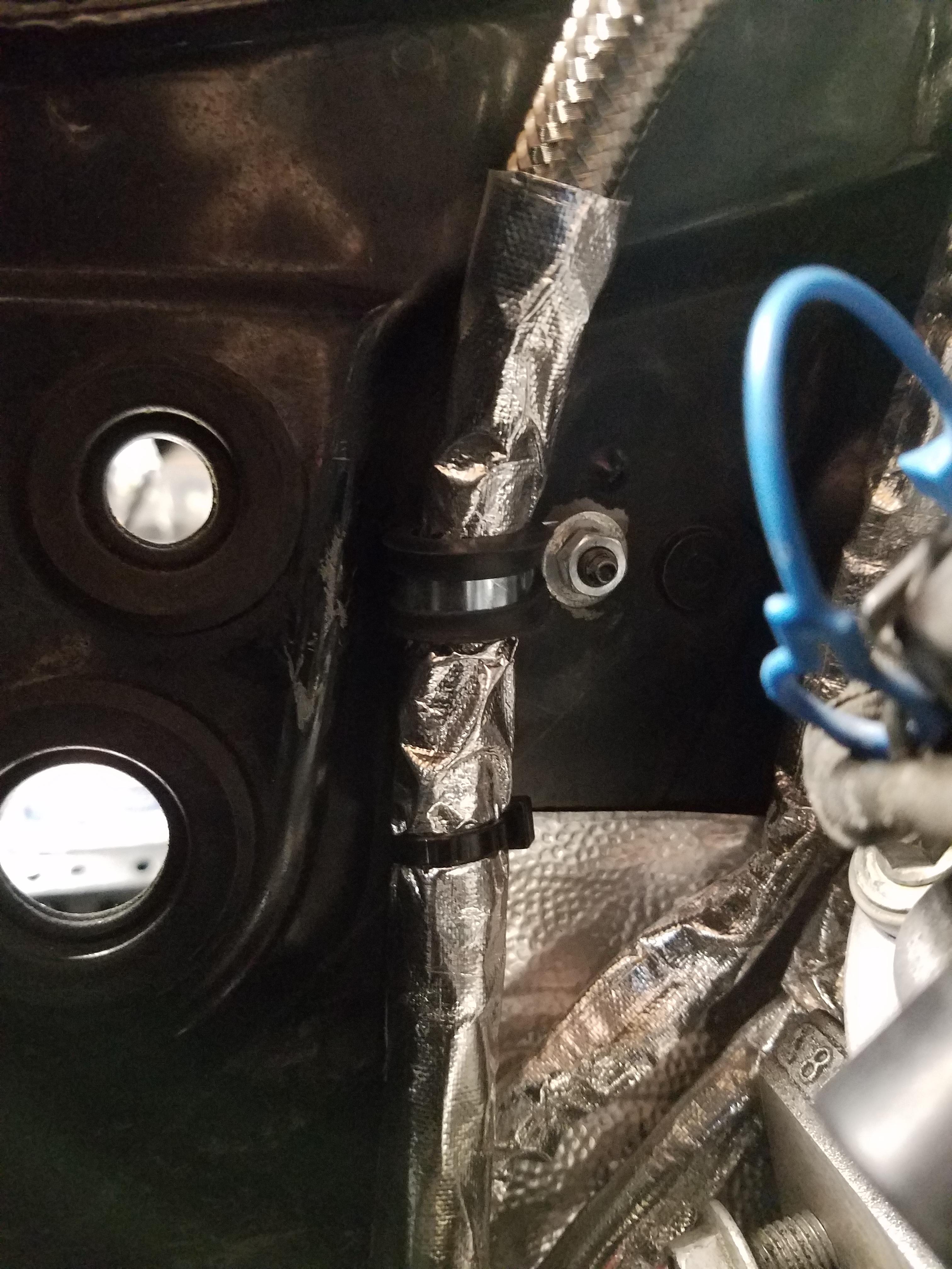
Covered the fuel hose near the engine with some more heat wrap. Found a convenient stud on the firewall to use a padded clamp to hold the hose in place
I used the following fittings/hose from Racer Parts Wholesale. You could find the same stuff on Amazon I think but RPW was a good bit cheaper
AER-FBA0600-10 -6 Aeroquip Stainless Steel Braided Hose - -6 Aeroquip Stainless Steel Braided Hose, 10' section
AER-FCM4432 Aeroquip 90 Degree Reusable Elbow Fitting- Black Anodized - -06 Aeroquip 90 Degree Reusable Elbow Fitting- Black
AER-FCM4412 Aeroquip Straight Reusable Swivel Fitting- Black Anodized - -06 Aeroquip Straight Reusable Swivel Fitting- Black
I clamp up the hose in some neat vice jaw holder that attach magnetically to the vice - not sure where I got them, but they have soft plastic jaws and they were handy in this case since they have a little slot for holding hose
I wrap the hose in electrical tape with a few tight wraps around. Then I use a metal cutting blade on my grinder, a thin one if possible, and make a cut around the hose. I try not to just cut the hose in one pass, but make about 4 cuts into the hose at around 90 degrees to each other. This prevents the braided material from fraying too much based on the way the blade cuts through it. Hope that makes sense.
I use a small screwdriver to push in the frayed bits as I slide the hose end over. Just take your time and work around in a circular pattern. If you don't, the frayed ends will get more difficult to deal with and you may need to recut for a clean start. Seat the end down as far as it will go. Then I use a small screwdriver again to push in hose from the inside to get under the inside lip of the hose end. This will just make it easier to screw in the other piece of the hose end.
At this point I try to use an air gun to blow out some of the junk that will get caught in the threads, or possibly in the hose itself.
I use this lube on the threads and on the part that slides into the hose itself.
I also put a piece of tape on the hose where the bottom of the hose end stops. This let's me know if the hose end is pulling up as I tighten down the connection. If you use lube it's not usually a problem, but if you don't the friction of the connection can pull up the hose end away from the hose, and you won't have a good seal. Again, hope that makes sense.
Once all done, I took the hose into my basement utility sink and ran some hot water through it to flush out any debris. Used a small bottle brush for garage stuff and worked it into the hose where the new fitting is to clean out any junk.
With one end done, I connect it to my fuel filter/reg and then bring it back up to the engine keeping it tight to the inside of the frame rails, and mark where my next cut will be.
My filter/reg mounted. A few tips on this, I thought it would be a bit easier to route the hose up to the top of the tank, but I ended dropping my already empty tank - it wasn't too hard at all. Just be aware of some connections near the back of the tank that might get caught up. You just need to drop it enough to see where you are doing with the hose and get the length right.
Final connection with the fuel rail
Covered the fuel hose near the engine with some more heat wrap. Found a convenient stud on the firewall to use a padded clamp to hold the hose in place
Last edited by pj_mcgarvey; 12-14-2016 at 08:46 PM.
12-08-2016, 09:11 AM
#82
V8 Miata Enthusiast
Thread Starter
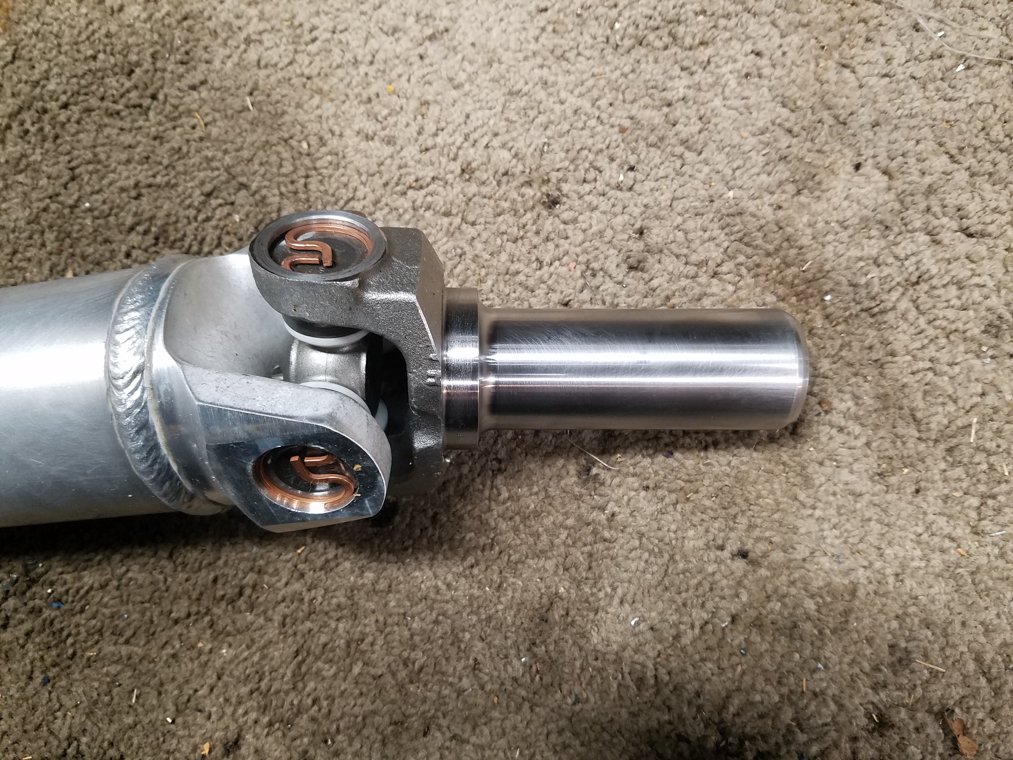
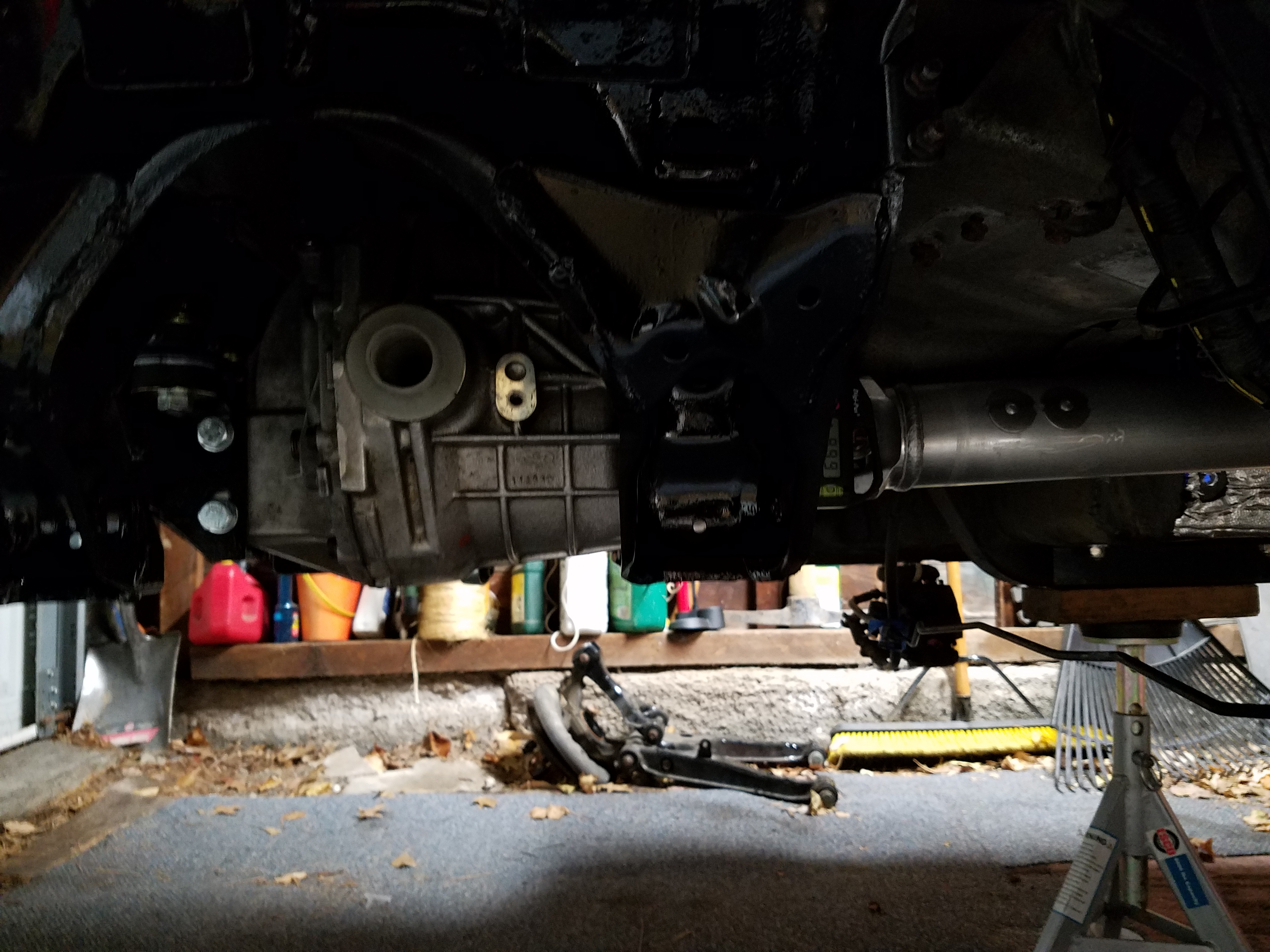
My new driveshaft, went all out and got the aluminum one
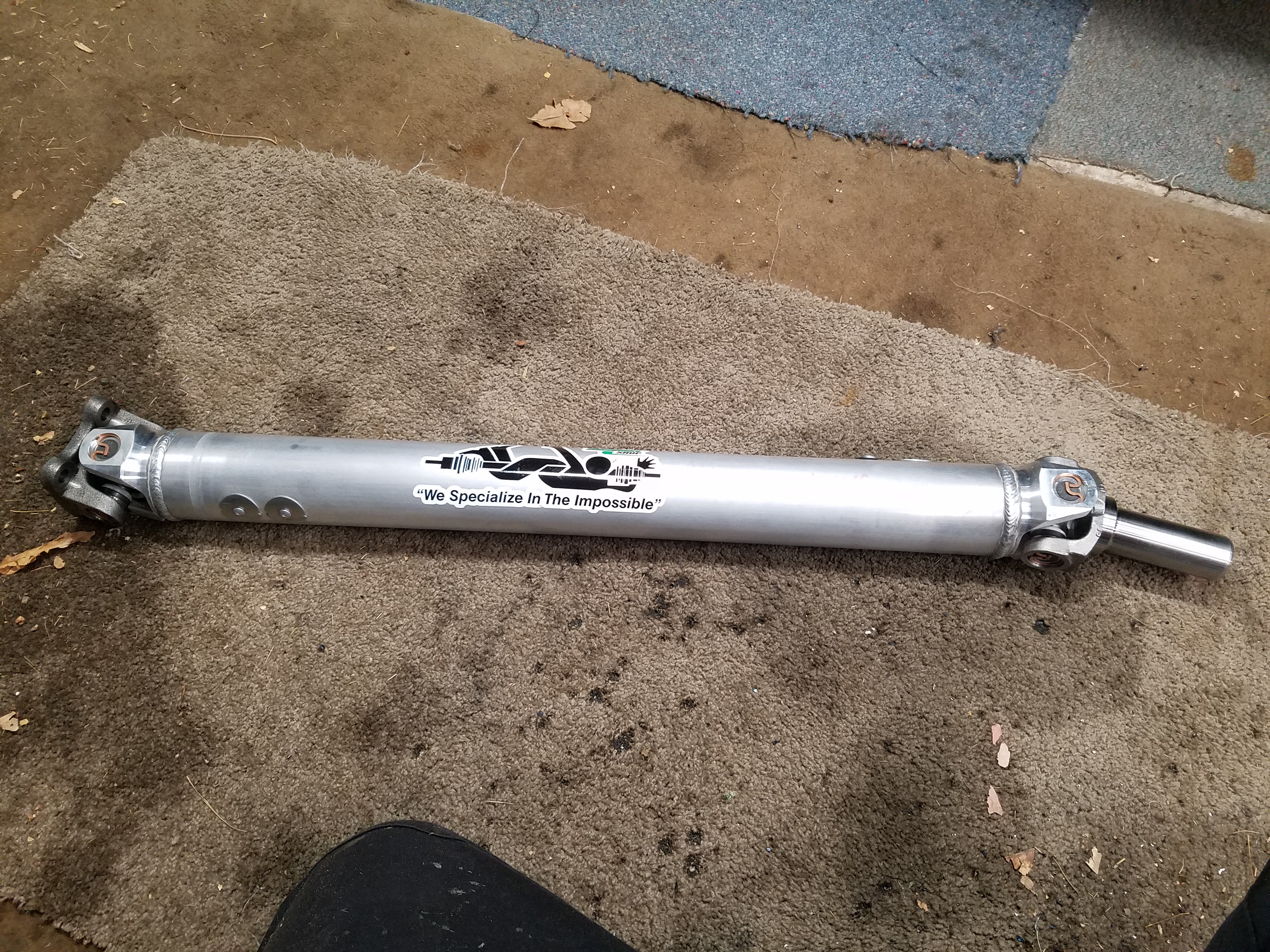
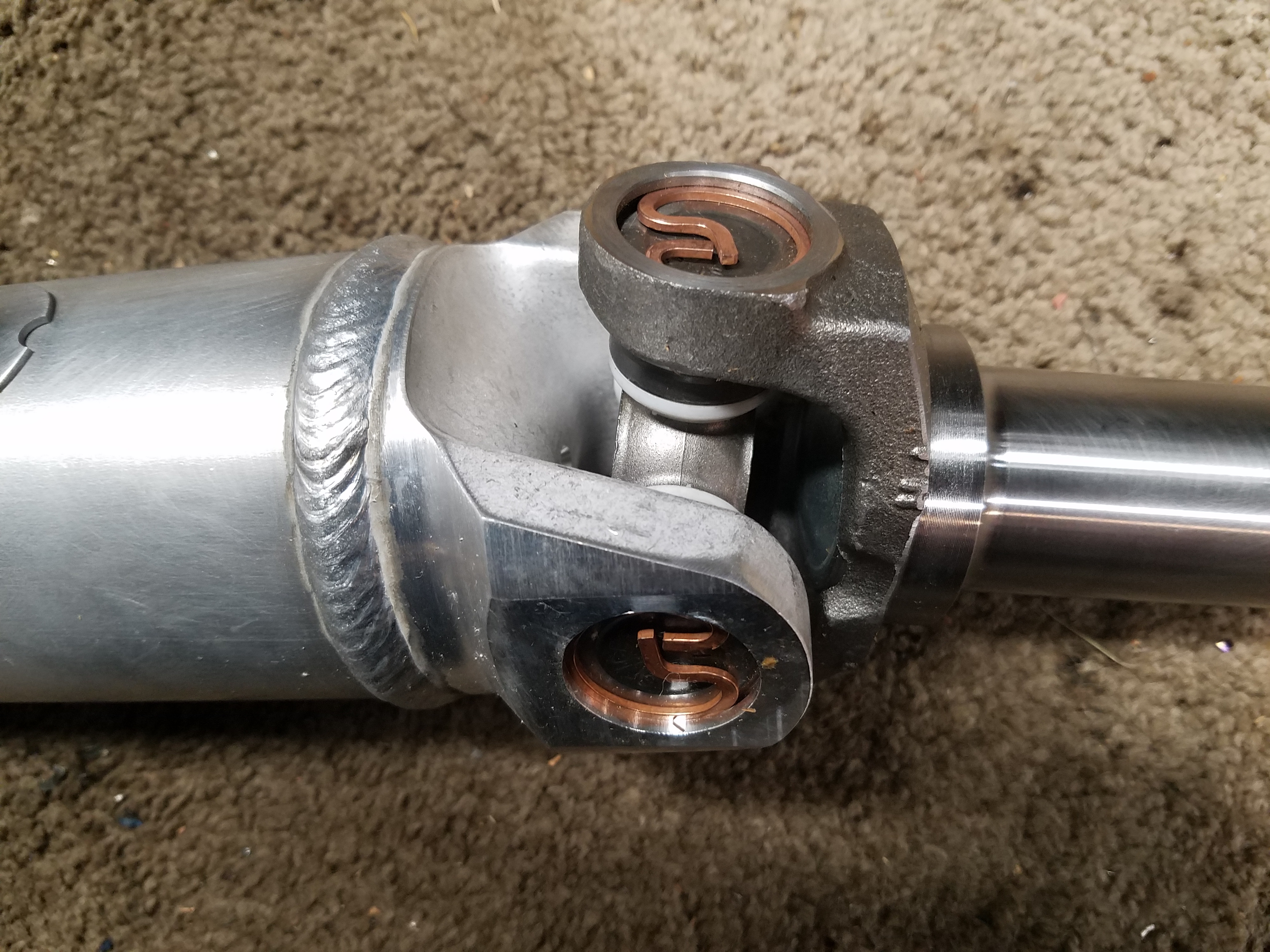
Some of the details on it, it's a nice piece, feels light, but I forget the weight difference between it and the steel one
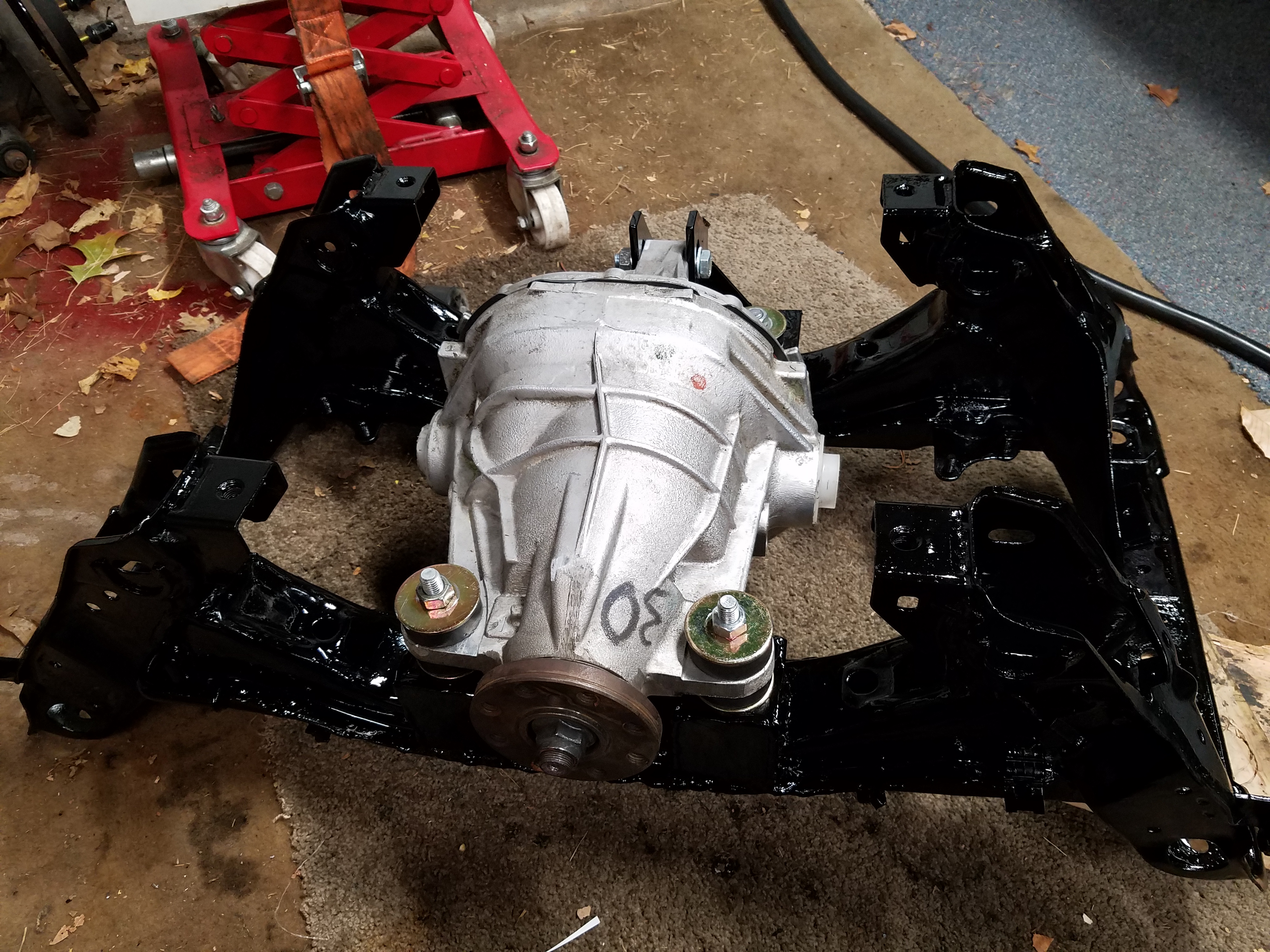
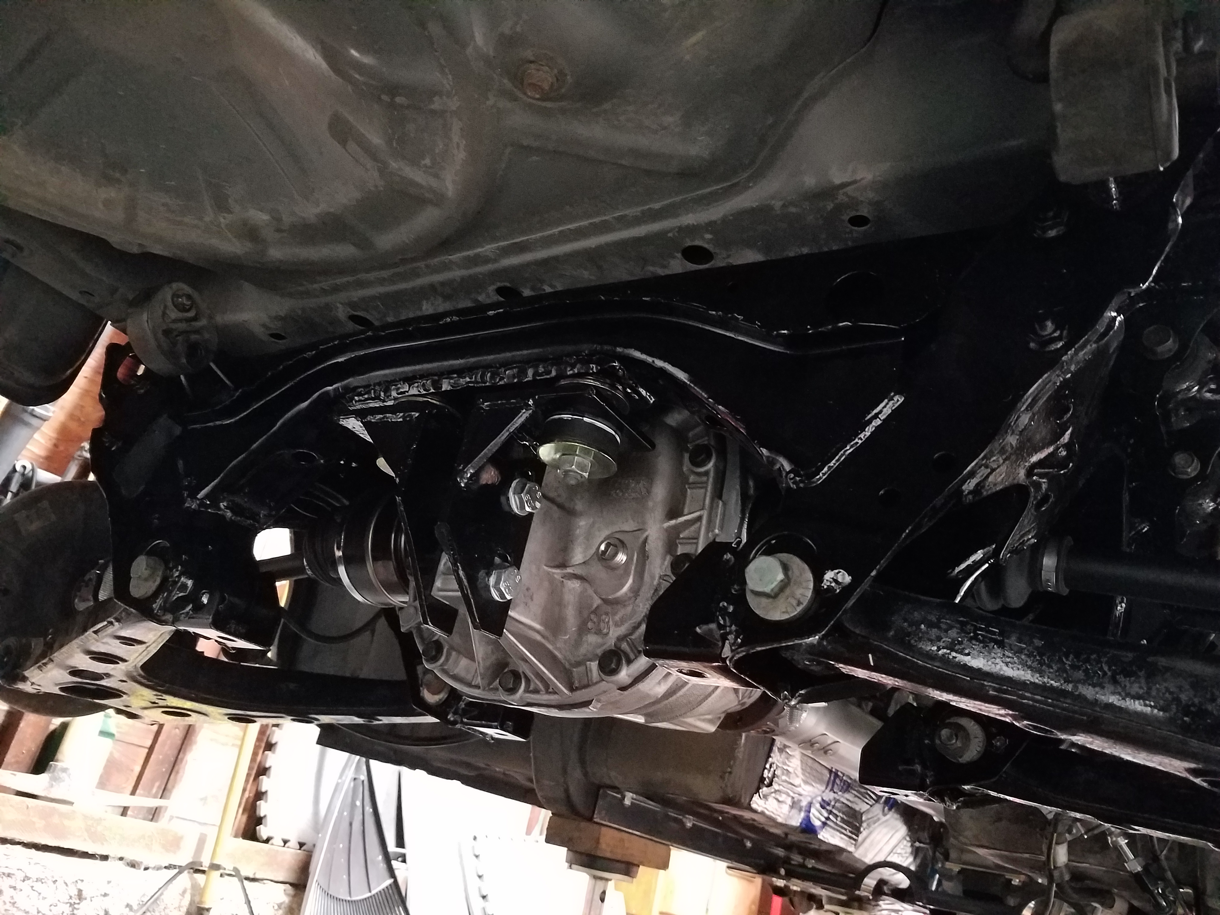
Subframe all welded up, POR15d and painted with gloss black. Turned out pretty nice
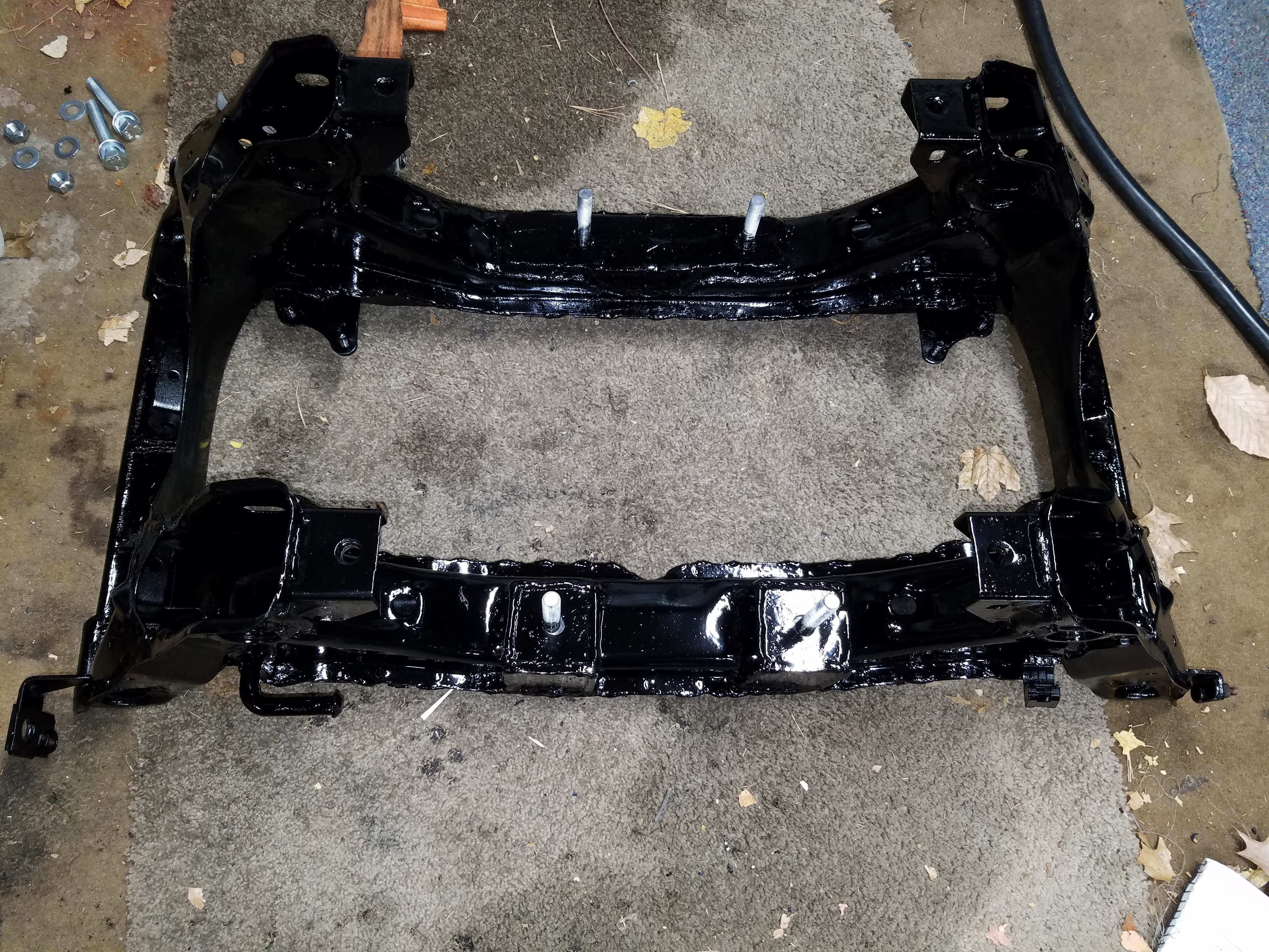
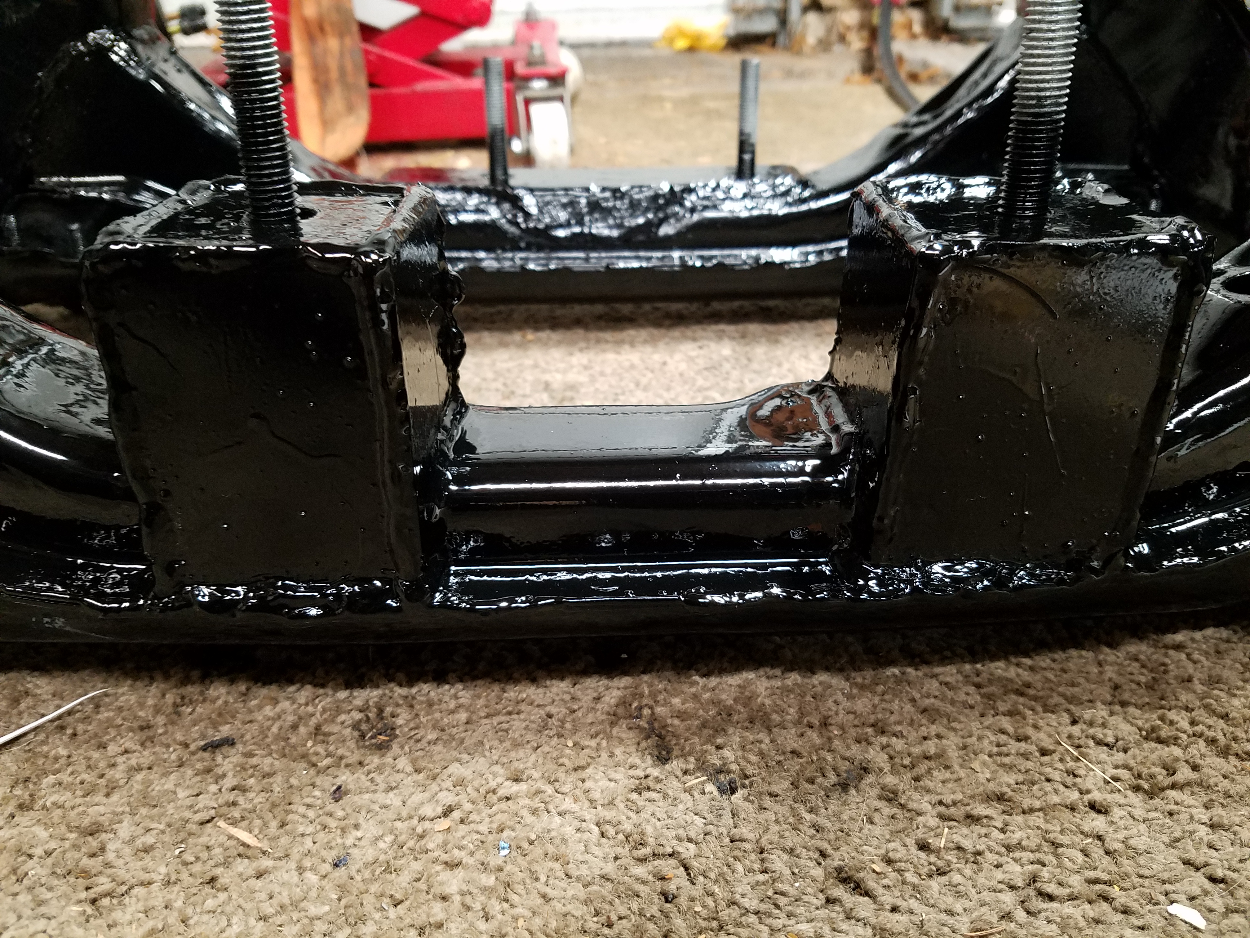
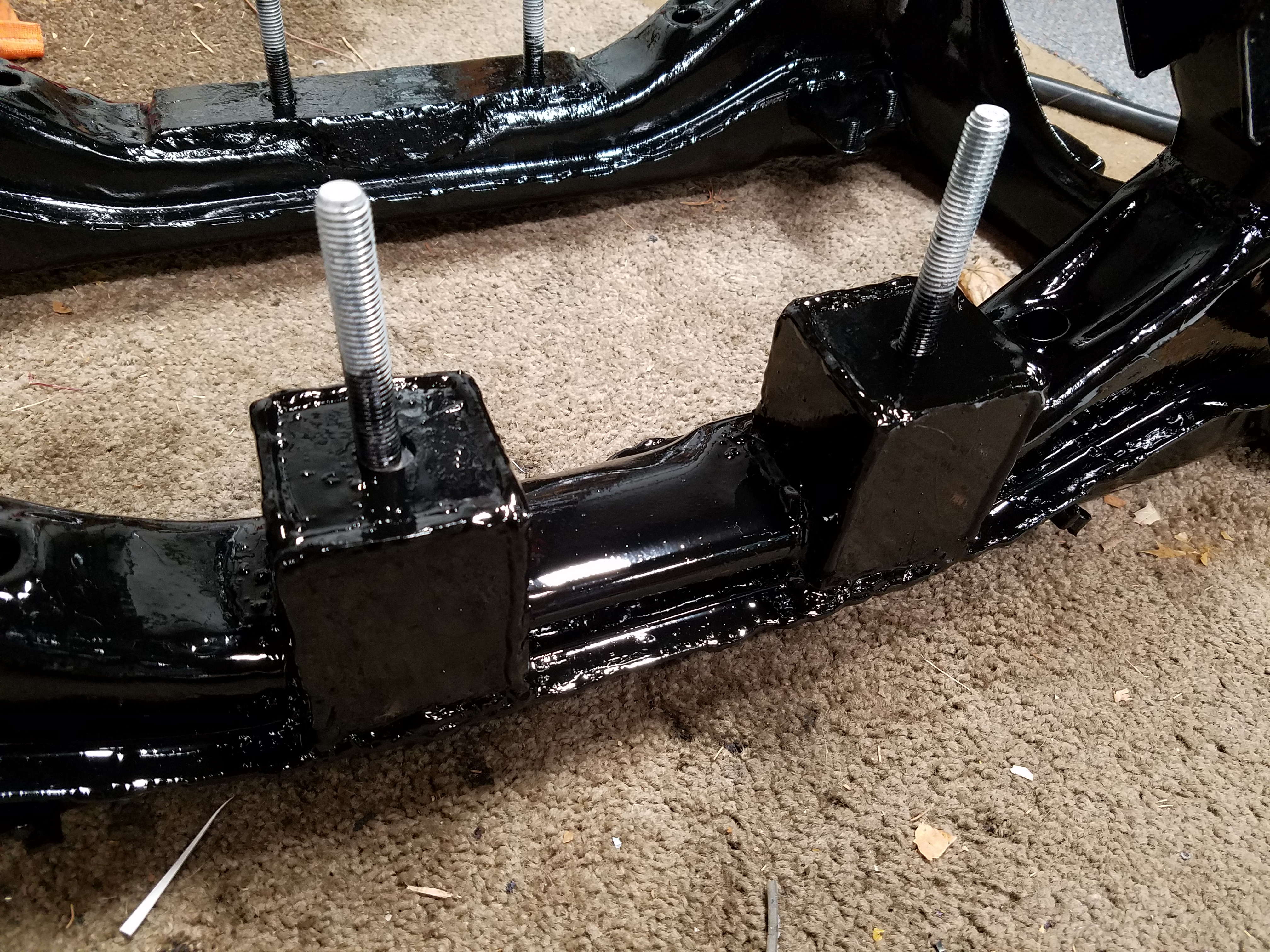
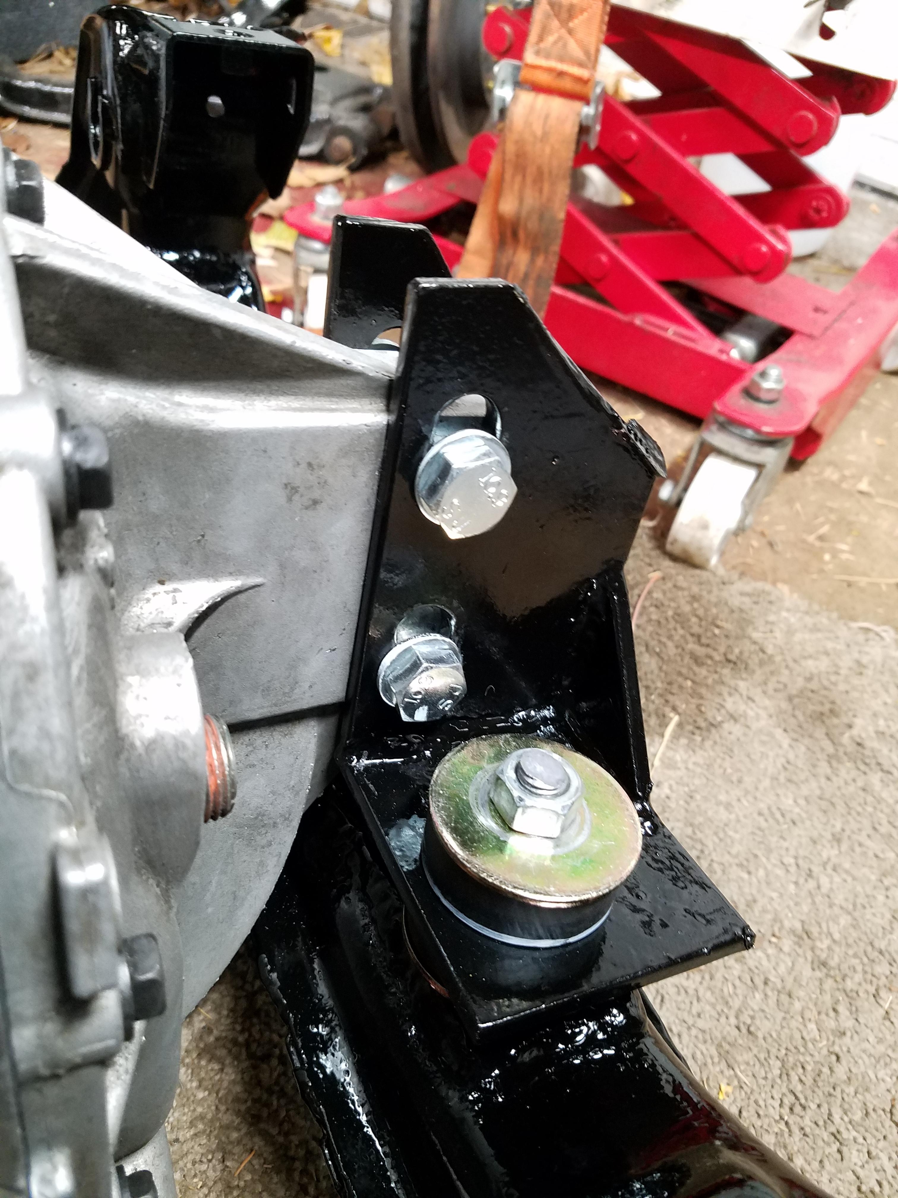
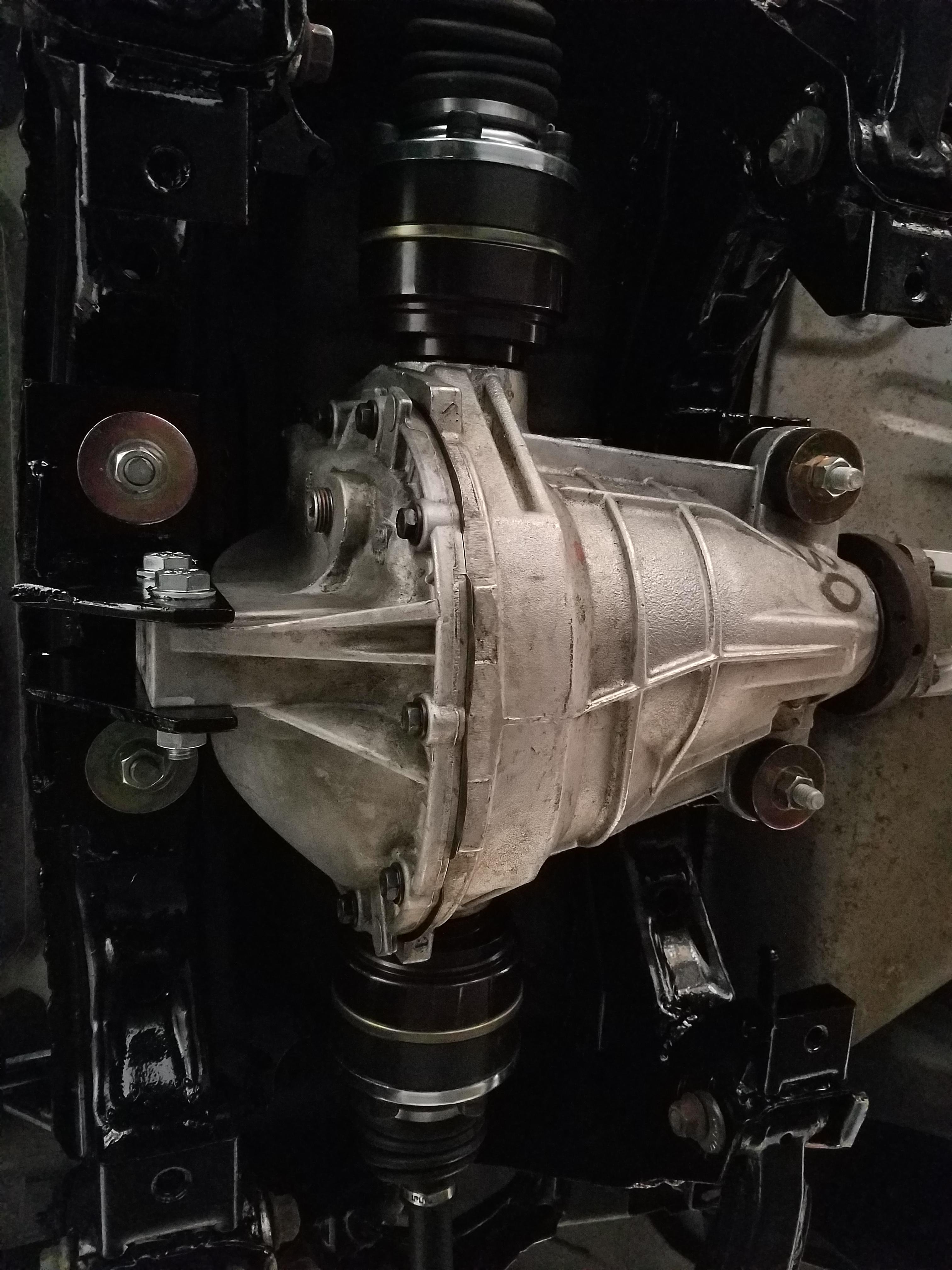
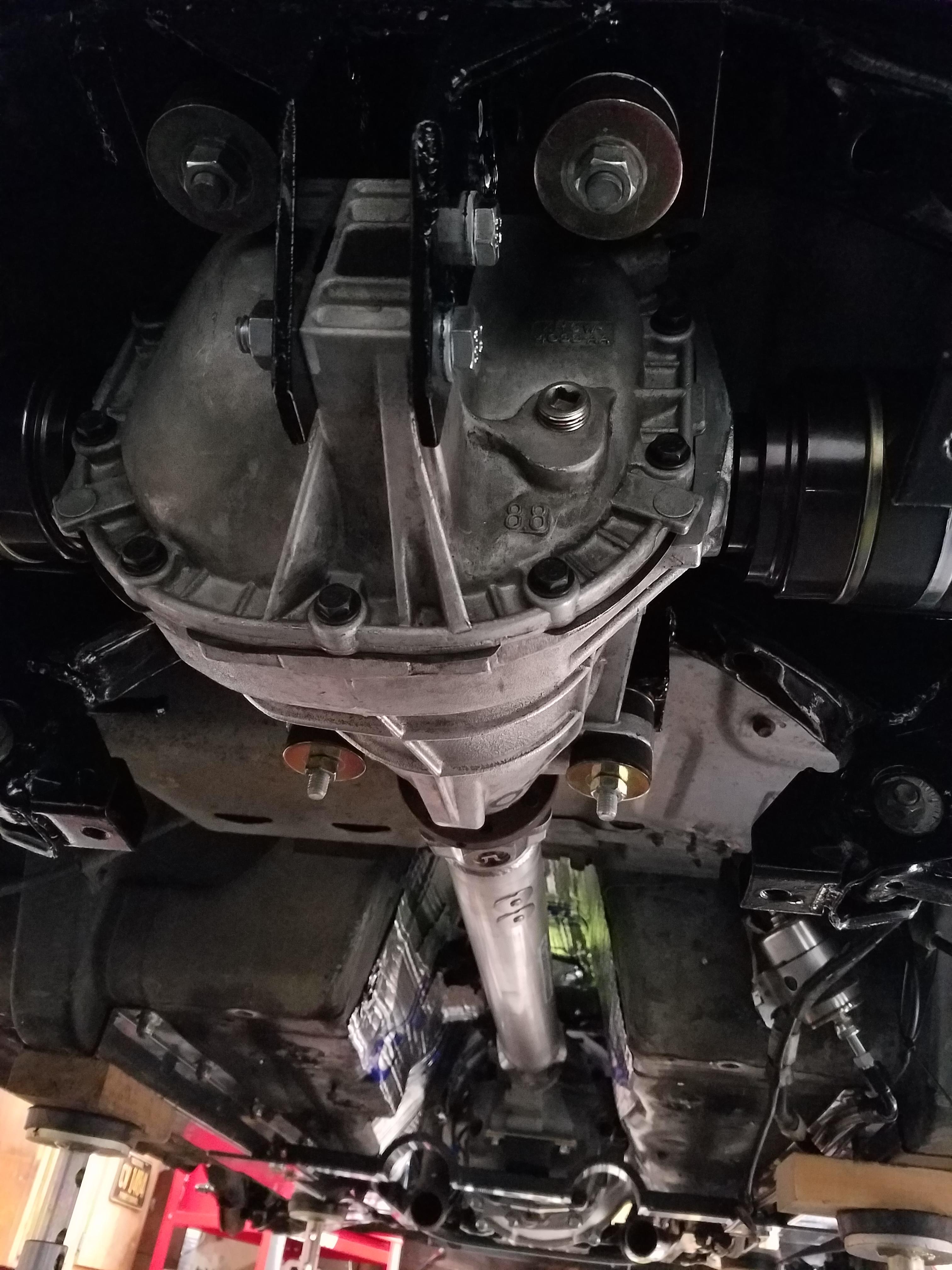
Rear diff mount L-brackets
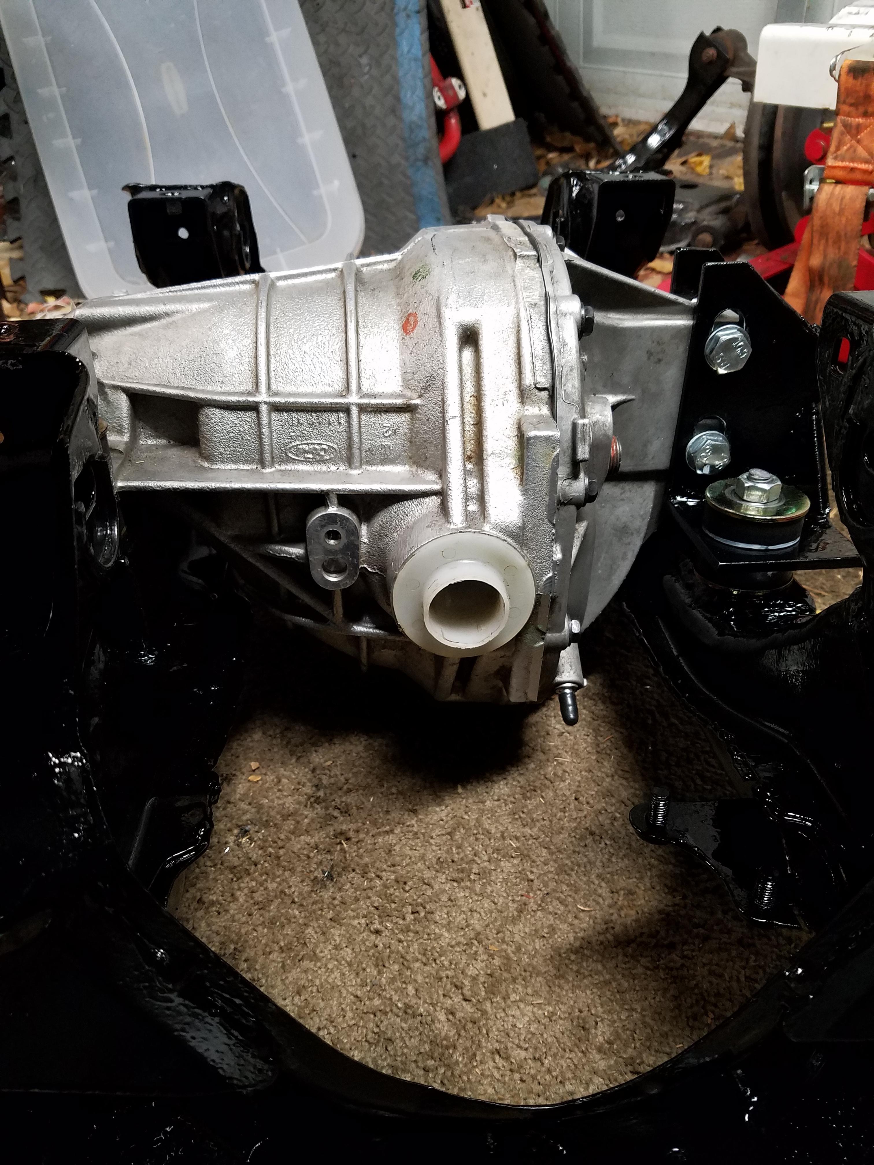
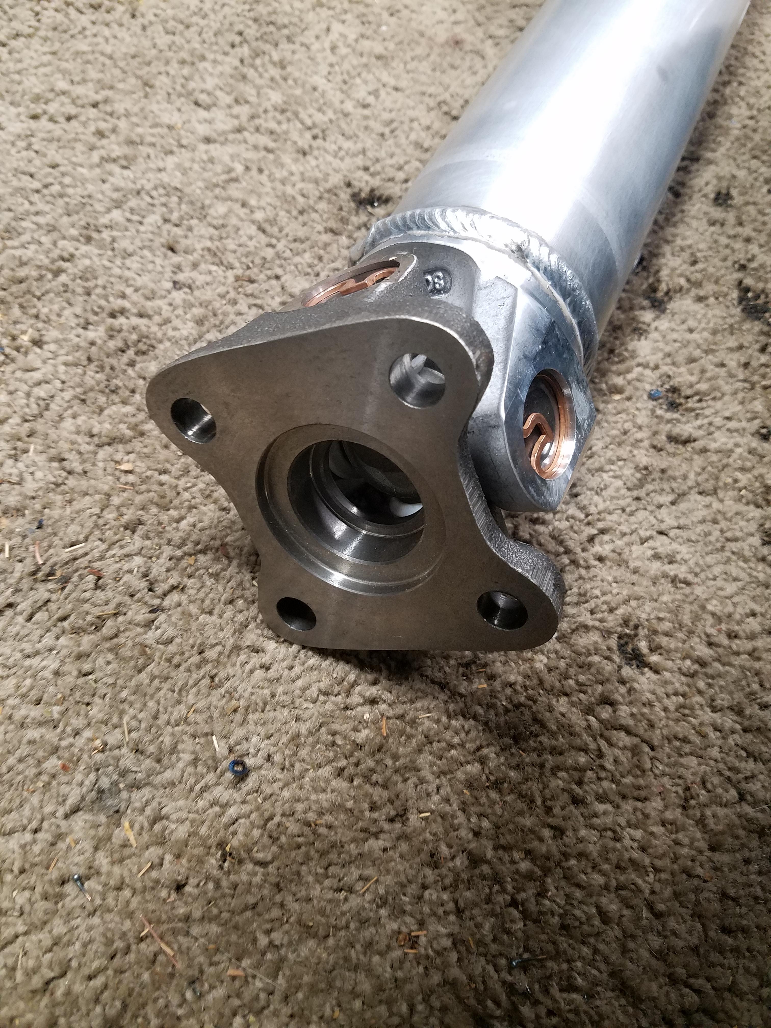
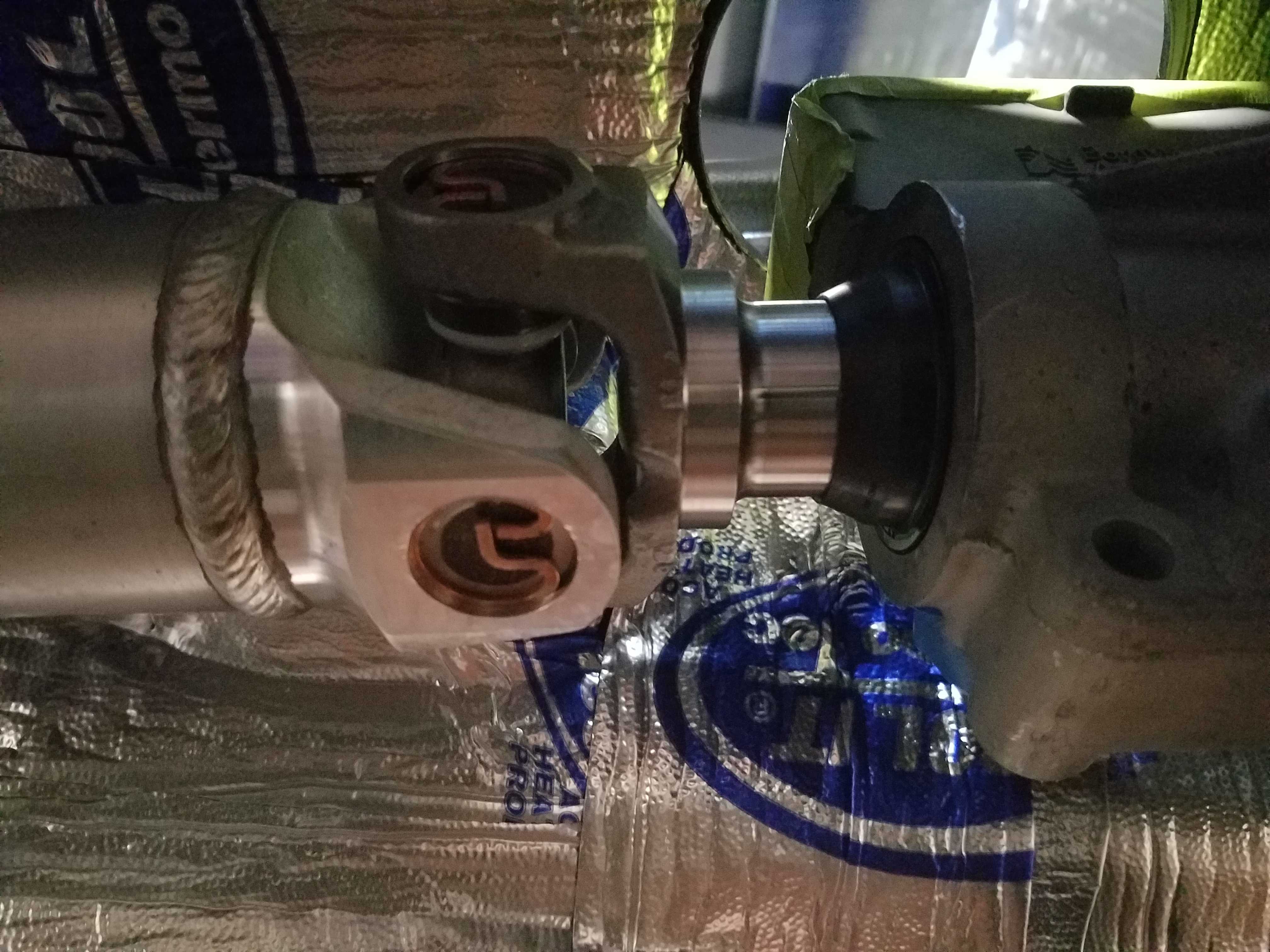
Connection to the T56 trans. If you measured correctly you should have about 3/4" to 1" of spacing between the lip of the T56 seal and where the slip yoke get thicker
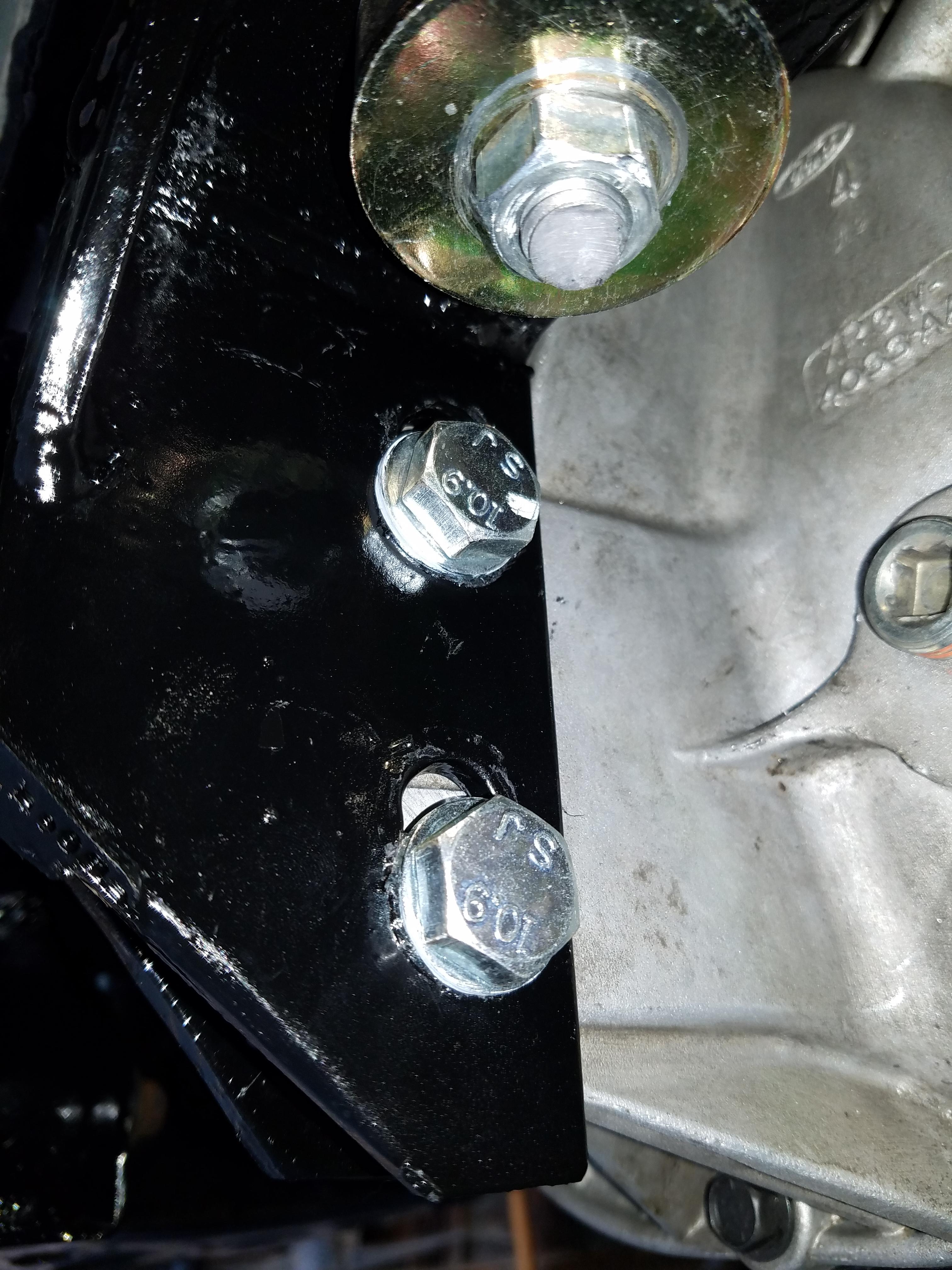
Mounted up the diff on the subframe on the ground, and laid it on the trans jack. Once bolted into the car (90 ft lbs on the studs, 60 ft lbs on the bolt) I measured the pinion angle. I built slots into the rear L-brackets so I could tilt the diff to get the pinion angle just right. The pinion angle on the diff was almost exactly 90 degrees as I had planned it ;-)
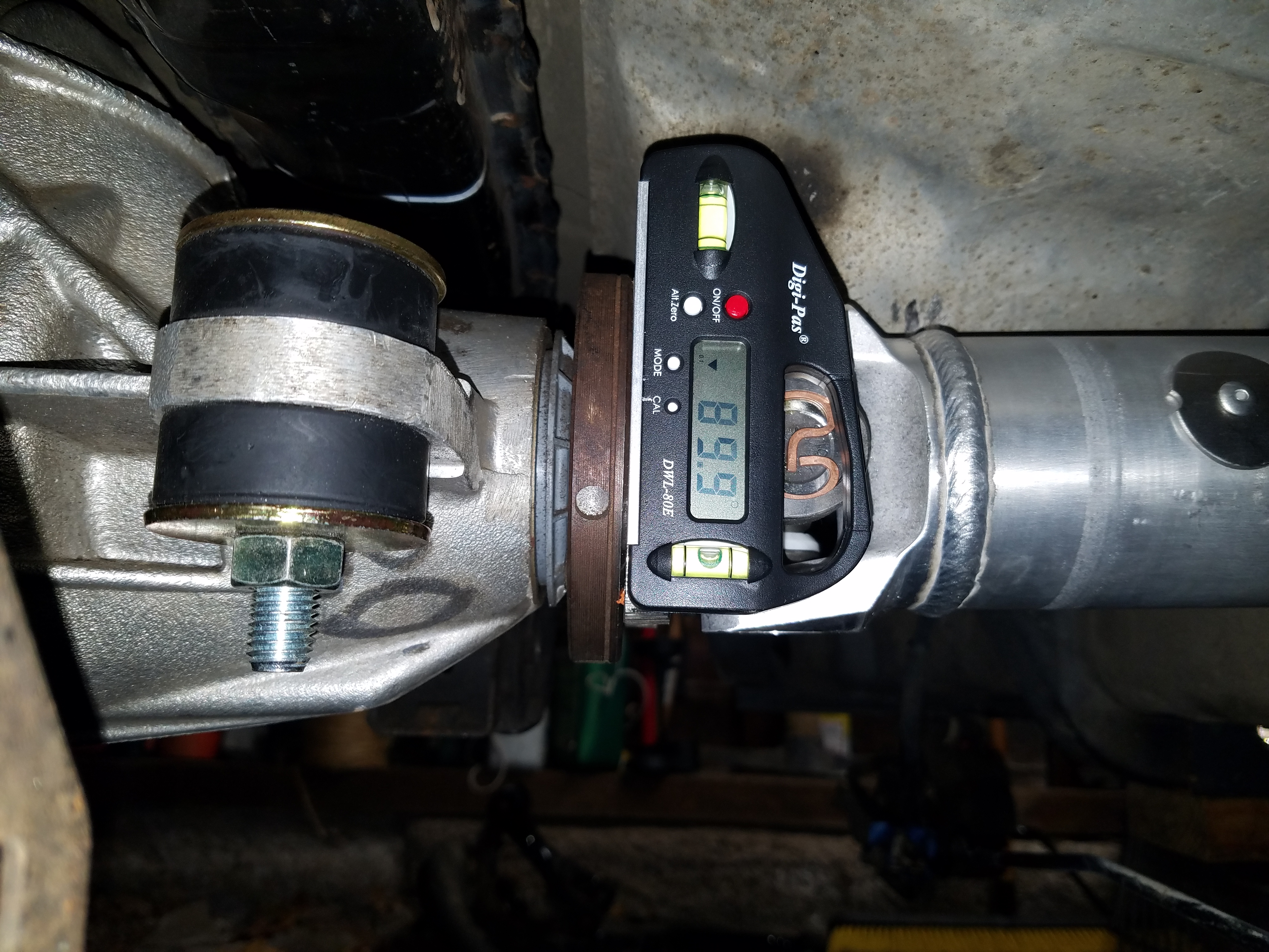
Used the 12mm 12 point bolts recommended.
Since the angle on the T56 output was 1.5 degrees I should end up within the recommended pinion angle range of 3 degrees. The important thing is that the two angles are measure with the parts facing "down". As power is applied to the driveline it will tend to want to swing up and become more straight, or closer to 0 degrees.
Pinion Angle - Wolfe Race Craft
I had to clearance the aluminum heat shield under the gas tank a bit as it was less than an inch from the spinning driveshaft. Since the diff mounts are poly mounts, there shouldn't be much movement anyway.
Some of the details on it, it's a nice piece, feels light, but I forget the weight difference between it and the steel one
Subframe all welded up, POR15d and painted with gloss black. Turned out pretty nice
Rear diff mount L-brackets
Connection to the T56 trans. If you measured correctly you should have about 3/4" to 1" of spacing between the lip of the T56 seal and where the slip yoke get thicker
Mounted up the diff on the subframe on the ground, and laid it on the trans jack. Once bolted into the car (90 ft lbs on the studs, 60 ft lbs on the bolt) I measured the pinion angle. I built slots into the rear L-brackets so I could tilt the diff to get the pinion angle just right. The pinion angle on the diff was almost exactly 90 degrees as I had planned it ;-)
Used the 12mm 12 point bolts recommended.
Since the angle on the T56 output was 1.5 degrees I should end up within the recommended pinion angle range of 3 degrees. The important thing is that the two angles are measure with the parts facing "down". As power is applied to the driveline it will tend to want to swing up and become more straight, or closer to 0 degrees.
Pinion Angle - Wolfe Race Craft
I had to clearance the aluminum heat shield under the gas tank a bit as it was less than an inch from the spinning driveshaft. Since the diff mounts are poly mounts, there shouldn't be much movement anyway.
12-08-2016, 09:26 AM
#83
V8 Miata Enthusiast
Thread Starter
If you find yourself with some free time over the holidays, you should check out the build series for "Project Binky". It's an epic build, and has some nice humor as well.
It's also where I picked up the idea for this digital angle gauge which has been very helpful so far
https://www.amazon.com/gp/product/B001NPJGL0
It's also where I picked up the idea for this digital angle gauge which has been very helpful so far
https://www.amazon.com/gp/product/B001NPJGL0
12-08-2016, 11:24 AM
#84
V8 Miata Follower

PJ,
looks like you are making some crazy fast progress!
I just have a couple of concerns. First, are you not concerned about the diff being able to move around since you put slots in it? Do you plan to fix its location somehow once you get it set? Without some math in reference to the torque about the axle moment and bolt clamp loads, Id be concerned with that.
Second, Not sure if im just reading this wrong, but it appears to me that you have the rear pinion angle DOWN, which would be incorrect. unless your tail-shaft of the trans is pointed up! lol.
Drawing a center-line through the engine crankshaft through the output shaft, and a center-line through the diff pinion, these center-lines should be parallel to each other.
12-08-2016, 02:17 PM
#85
V8 Miata Enthusiast
Thread Starter
PJ,
looks like you are making some crazy fast progress!
I just have a couple of concerns. First, are you not concerned about the diff being able to move around since you put slots in it? Do you plan to fix its location somehow once you get it set? Without some math in reference to the torque about the axle moment and bolt clamp loads, Id be concerned with that.
Second, Not sure if im just reading this wrong, but it appears to me that you have the rear pinion angle DOWN, which would be incorrect. unless your tail-shaft of the trans is pointed up! lol.
Drawing a center-line through the engine crankshaft through the output shaft, and a center-line through the diff pinion, these center-lines should be parallel to each other.
Drawing a center-line through the engine crankshaft through the output shaft, and a center-line through the diff pinion, these center-lines should be parallel to each other.
Solid mounted drivelines would have less angle built in, b/c they will move less. Poly is next, then rubber would have the most angle built in.
Under power the axles will twist moving the car forward and the diff will rotate upwards (countering the rotation of the axles). A 3 degree down angle will become zero or close to it, and the output angle of the trans and input angle of the diff should be parallel (in theory - b/c we can't actually measure the angle under power).
So my trans is 87.5 degrees down, and my diff is 90 degrees. That's a 2.5 degree down angle which is pretty ideal I think.
One other point is that when I measure the output angle at the front of the engine (crank damper) and the rear of the trans (the flat where the output seal is), I get measurements that were one degree different. Not sure if that's concerning since there could be small differences in machining, etc. but I went with the rear of the trans measurement since it was closer to where the driveshaft mounted.
I guess only time will tell once I get this on the road and do some driving, whether there will be any vibrations. the good thing is that with all the poly mounts I'm using hopefully the measurements I take will not change much during driving, vs. old rubber bushings on a lifted leaf spring rear, etc. etc. which is probably a much more difficult scenario to get right.
Please do provide any thoughts on whether this sounds right. I'm relatively new to rear wheel drive stuff so I've not spent much thinking about this problem at all, only going off what I've read.
12-08-2016, 02:42 PM
#86
V8 Miata Follower
PJ,
I would agree, we are on the same page as far as the concept goes. However there is so much information out there about driveline angles, you have to be careful because there is not one rule that applies to all applications.
Many hardcore hotrodders and drag racers might tell you to put some degree of pinion down angle for the reasons you stated above. However their only concerns are wide open throttle down a straight line, in a car with a live axle ; that doesnt get driven on a street.
For our application, I would highly recommend setting angle at pinion up. On an IRS car, the differential will move very little, if at all under normal conditions. Consider this, your driving along at highway speeds, just taking you newly finished V8 miata on a scenic trip. Your diff isnt loaded, your diff is pinion down, trans centerline down. This is no bueno.
Even still, under wide open, hard launching on slicks, I would bet there is not nearly 2�+ degrees change in angle or whatever it is you need. And even if there was, just consider where you car will be spending the majority of its time.
Be my guest to just run it as you have it and see what happens! It wont be the end of the world, and maybe you will prove me wrong! Shouldnt be too much of a hassle to fix down the road if you need to. Just my two cents! I am certainly no expert, so I would welcome someone else to come in and put me in my place if I am wrong! haha
12-08-2016, 11:16 PM
#87
V8 Miata Follower

I figured I would shim my rear L-brackets to achieve the adjustment instead of slots. There has been some forum stuff on rear end clunking which was attributed to the use on non-knurled bolts going through the Ford diff cover. Just my 2 cents.
12-09-2016, 06:22 AM
#88
V8 Miata Enthusiast
Thread Starter
Yeah, I was thinking I could use a larger washer on the bolts going through the cover, for more clamping force. But if you think about the twisting loads on the diff they're not really in a direction that would try to move them much. There's alot more strech load on the poly mount bolts.
12-09-2016, 06:39 AM
#89
V8 Miata Enthusiast
Thread Starter
PJ,
I would agree, we are on the same page as far as the concept goes. However there is so much information out there about driveline angles, you have to be careful because there is not one rule that applies to all applications.
Many hardcore hotrodders and drag racers might tell you to put some degree of pinion down angle for the reasons you stated above. However their only concerns are wide open throttle down a straight line, in a car with a live axle ; that doesnt get driven on a street.
For our application, I would highly recommend setting angle at pinion up. On an IRS car, the differential will move very little, if at all under normal conditions. Consider this, your driving along at highway speeds, just taking you newly finished V8 miata on a scenic trip. Your diff isnt loaded, your diff is pinion down, trans centerline down. This is no bueno.
Even still, under wide open, hard launching on slicks, I would bet there is not nearly 2�+ degrees change in angle or whatever it is you need. And even if there was, just consider where you car will be spending the majority of its time.
Be my guest to just run it as you have it and see what happens! It wont be the end of the world, and maybe you will prove me wrong! Shouldnt be too much of a hassle to fix down the road if you need to. Just my two cents! I am certainly no expert, so I would welcome someone else to come in and put me in my place if I am wrong! haha
I would agree, we are on the same page as far as the concept goes. However there is so much information out there about driveline angles, you have to be careful because there is not one rule that applies to all applications.
Many hardcore hotrodders and drag racers might tell you to put some degree of pinion down angle for the reasons you stated above. However their only concerns are wide open throttle down a straight line, in a car with a live axle ; that doesnt get driven on a street.
For our application, I would highly recommend setting angle at pinion up. On an IRS car, the differential will move very little, if at all under normal conditions. Consider this, your driving along at highway speeds, just taking you newly finished V8 miata on a scenic trip. Your diff isnt loaded, your diff is pinion down, trans centerline down. This is no bueno.
Even still, under wide open, hard launching on slicks, I would bet there is not nearly 2�+ degrees change in angle or whatever it is you need. And even if there was, just consider where you car will be spending the majority of its time.
Be my guest to just run it as you have it and see what happens! It wont be the end of the world, and maybe you will prove me wrong! Shouldnt be too much of a hassle to fix down the road if you need to. Just my two cents! I am certainly no expert, so I would welcome someone else to come in and put me in my place if I am wrong! haha
The poly bushings are definitely stiff, so hard to imagine alot of movement happening, but I'll bet a gopro under the car or some other measuring device would tell us pretty quickly.
Oh wait, youtube!
Ford Cobra IRS diff - like mine:
12-09-2016, 08:33 AM
#90
V8 Miata Zealot
I would suggest one of these cover braces: Steeda IRS Mustang Differential Cover Brace 555-8118 (99-04 Cobra) - Free Shipping. I have replaced dozens of broken stock Cobra covers over the years. They just can't handle the abuse.
12-11-2016, 01:23 PM
#91
V8 Miata Follower
Now I am confused. The pic of your cover is different than mine. Mine has a rectangular block coming off the back where two bolts go through to attach to the L brackets that I made. I can shim either these brackets or the nose to adjust the angle. Does anyone else see the need for the cover brace with this setup?
12-11-2016, 09:16 PM
#92
V8 Miata Enthusiast
Thread Starter
Now I am confused. The pic of your cover is different than mine. Mine has a rectangular block coming off the back where two bolts go through to attach to the L brackets that I made. I can shim either these brackets or the nose to adjust the angle. Does anyone else see the need for the cover brace with this setup?
My thoughts are that rubber bushings will probably allow alot more twisting of the diff. So when you are heavily in and out of power that diff will flopping back and forth alot, creating alot of stress on the relatively weak aluminum cover. That and hard launches, grippy tires or any wheel hop will probably also spell certain death for any stress points.
01-03-2017, 08:51 PM
#93
V8 Miata Enthusiast
Thread Starter
Can't believe it's been a month since I posted, but nevertheless I've been chipping away at the project over the holidays. Alot of things are starting to come together. I've been able to complete alot of the welding tasks in the engine bay, which now allows me to move onto more delicate tasks like wiring and routing hoses of various kinds.
One thing I'm glad to have behind me is the power steering rack issue. I had to re-fabricate the initial bracket I had welded in due to clearance issues with the steering column U-joint. One begins to realize just how tight all the components are in this area. Since most will not have the issues I had with rack mounting, I won't go into detail and will move onto getting hydraulic power to the rack.
The only options I could find for power steering fittings are straight and 90 degree fittings, so this is what I did.
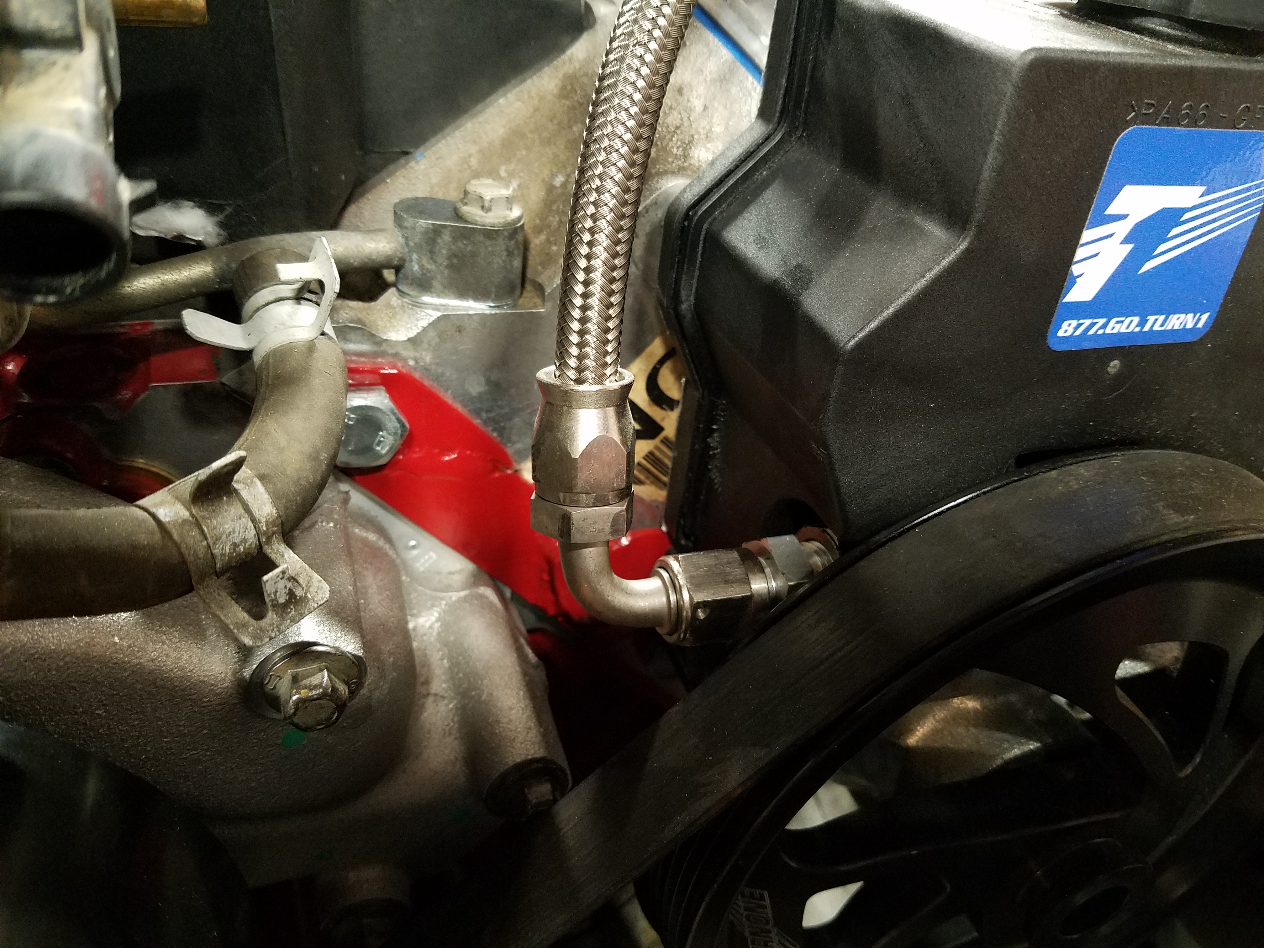
A 120 degree fitting would have allowed me to point the line down and route through the rack and make it look a bit neater. But this will work just fine. Up and over the reservoir. A conveniently located padded hose clamp will keep it from rubbing against anything.
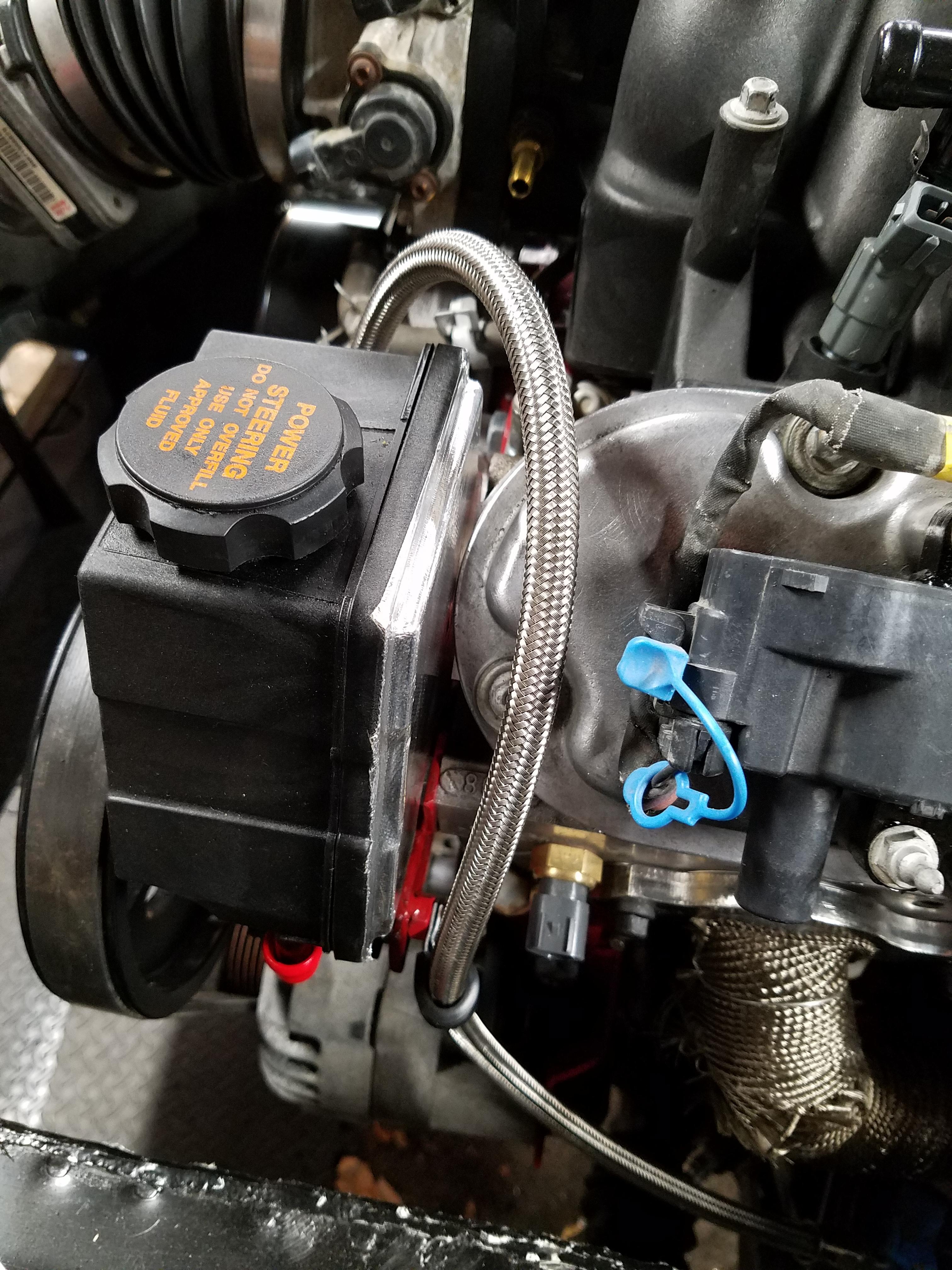
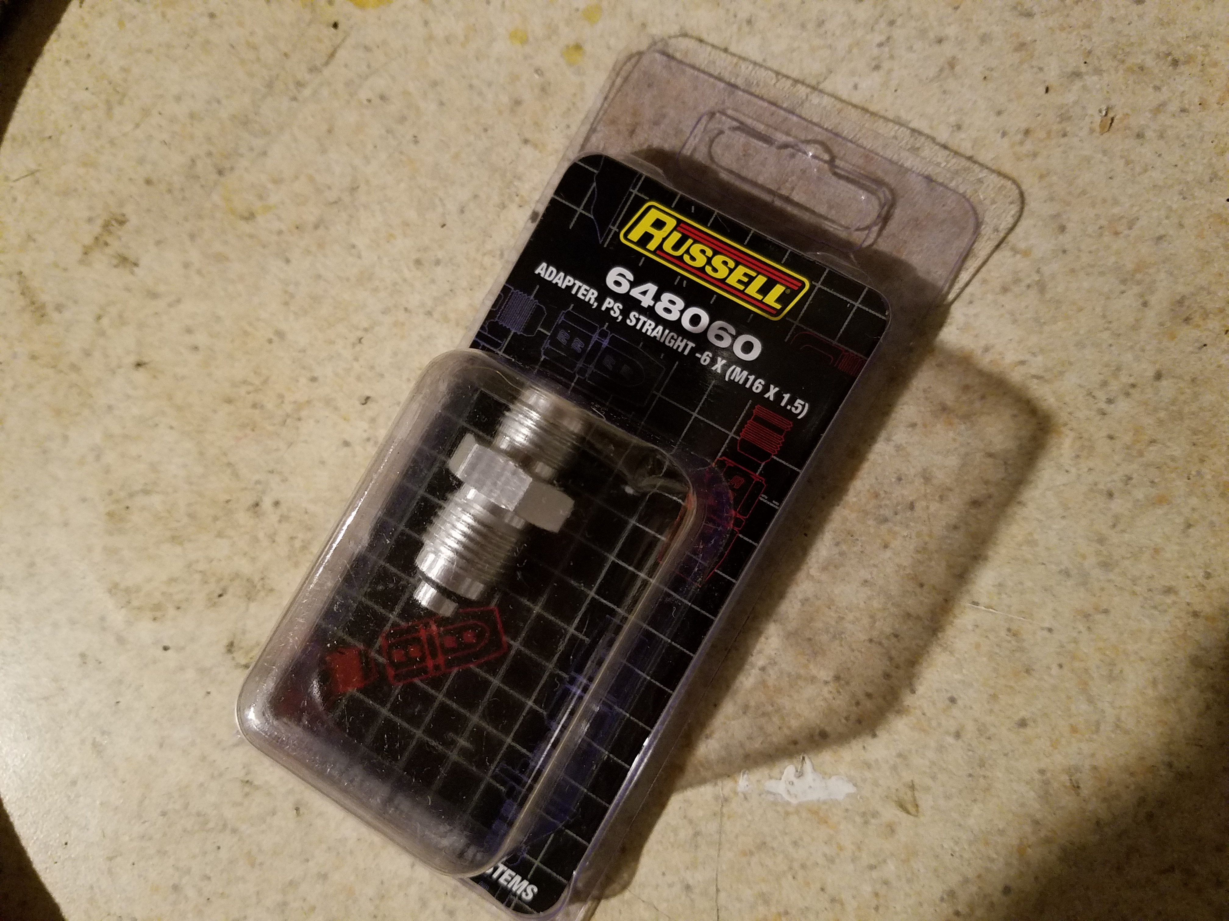
This is the fitting to use for the high pressure side. Not exactly designed for this application as the OEM fitting is a banjo fitting, but the thread size matches and others have used it with success. Just tightened it down snug. I'll keep an eye out for leaks.
I reused the oem return line fitting and made some gentle bends so it points where I want it. Since I'm using a power steering cooler, that direction would be toward the radiator - the hose you see coming toward you in the pic.
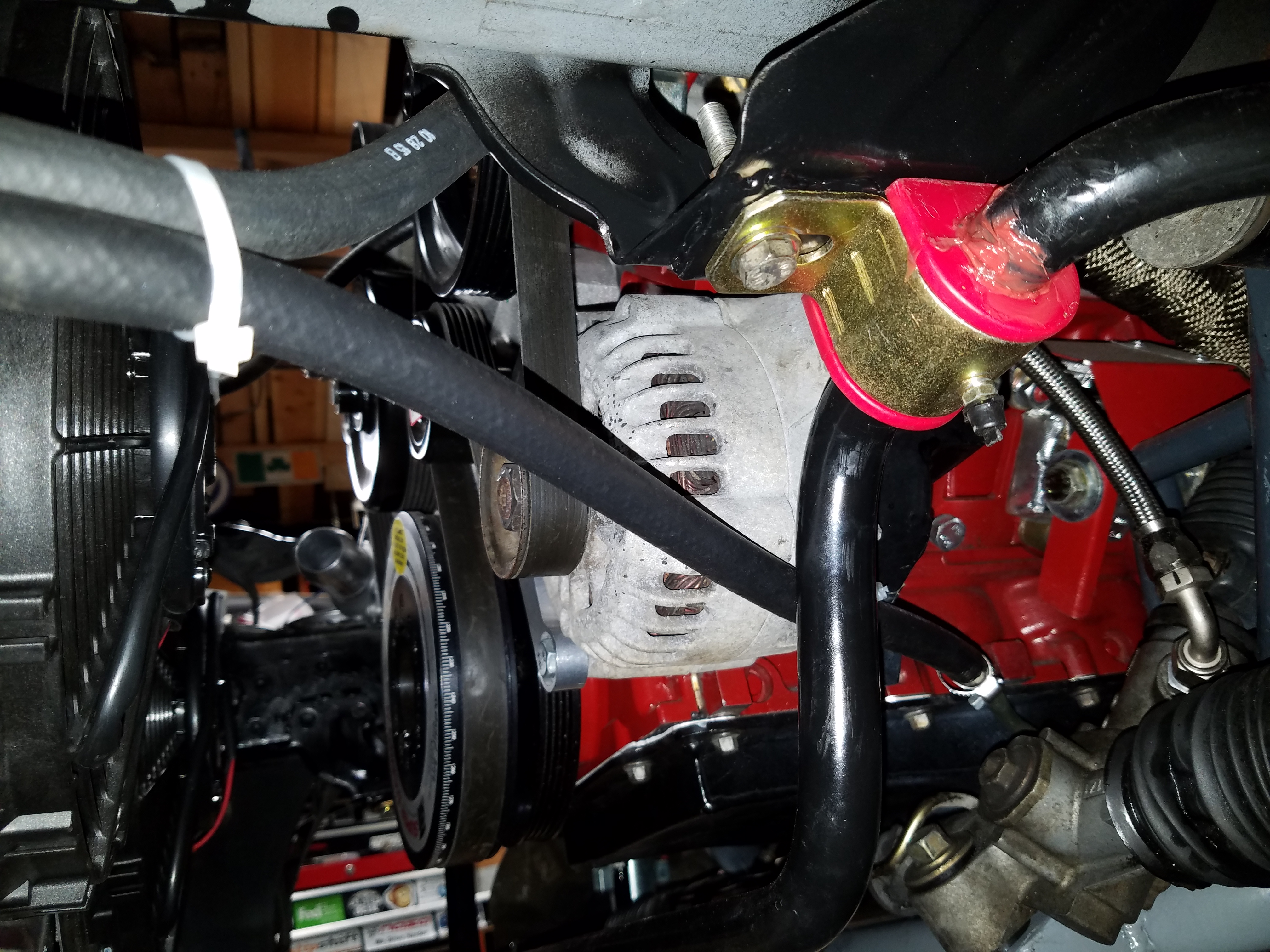
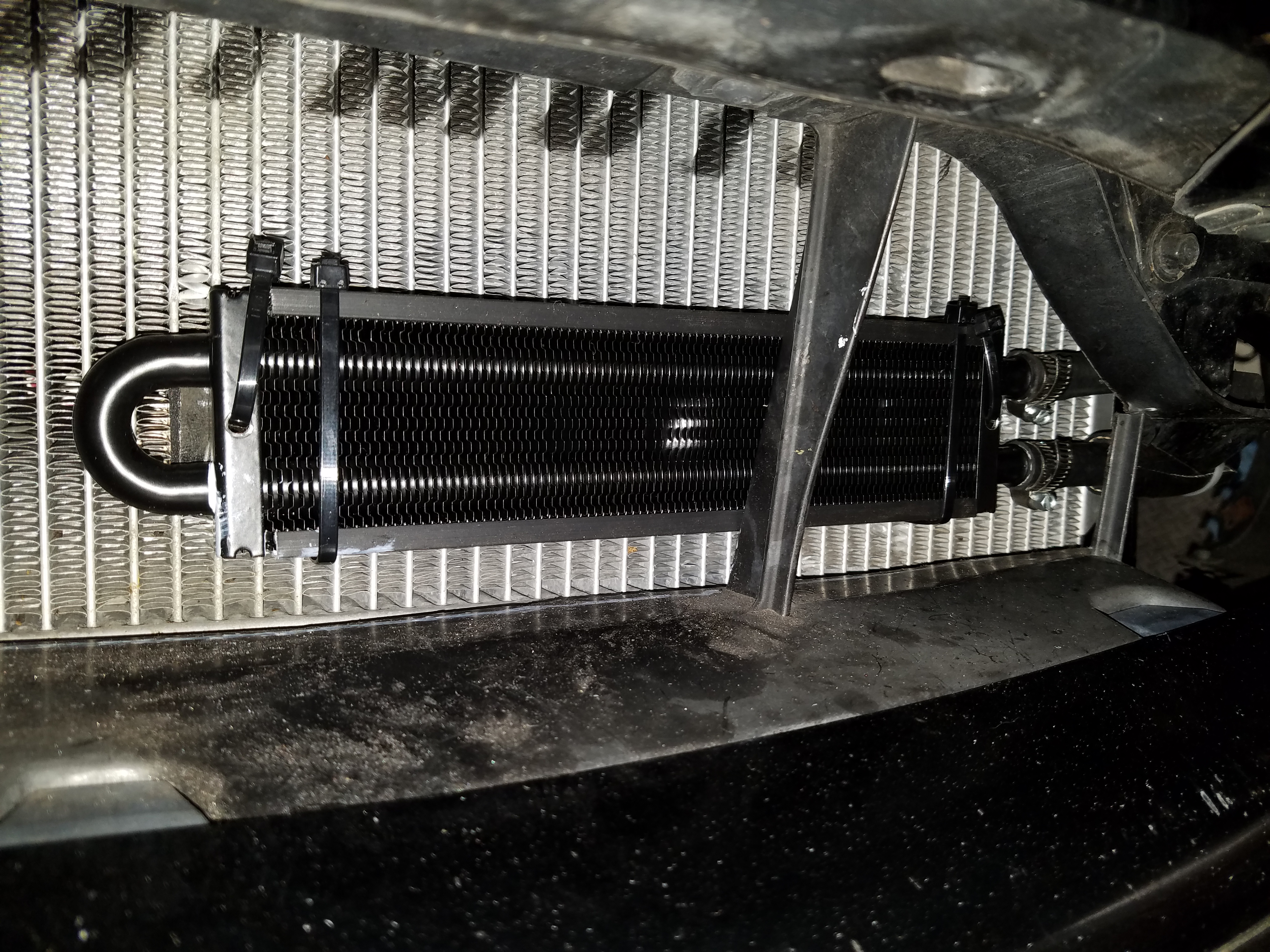
I used a Derale power steering cooler kit from Amazon. https://www.amazon.com/gp/product/B0006HNM66 and mounted it in front of the radiator using some zip ties. The plastic connectors that came with the kit worked well, but quickly broke as I was moving the cooler around to connect the hoses. I would suggest removing the radiator, installing the cooler and the hoses to it with plenty of room, then reinstall the rad so you can cut the hoses to length at the rack and reservoir without having to fiddle with them in a tight space. Some additional hose in the right size gave me enough to make all the connections https://www.amazon.com/gp/product/B000IYZLPM
One thing I'm glad to have behind me is the power steering rack issue. I had to re-fabricate the initial bracket I had welded in due to clearance issues with the steering column U-joint. One begins to realize just how tight all the components are in this area. Since most will not have the issues I had with rack mounting, I won't go into detail and will move onto getting hydraulic power to the rack.
The only options I could find for power steering fittings are straight and 90 degree fittings, so this is what I did.
A 120 degree fitting would have allowed me to point the line down and route through the rack and make it look a bit neater. But this will work just fine. Up and over the reservoir. A conveniently located padded hose clamp will keep it from rubbing against anything.
This is the fitting to use for the high pressure side. Not exactly designed for this application as the OEM fitting is a banjo fitting, but the thread size matches and others have used it with success. Just tightened it down snug. I'll keep an eye out for leaks.
I reused the oem return line fitting and made some gentle bends so it points where I want it. Since I'm using a power steering cooler, that direction would be toward the radiator - the hose you see coming toward you in the pic.
I used a Derale power steering cooler kit from Amazon. https://www.amazon.com/gp/product/B0006HNM66 and mounted it in front of the radiator using some zip ties. The plastic connectors that came with the kit worked well, but quickly broke as I was moving the cooler around to connect the hoses. I would suggest removing the radiator, installing the cooler and the hoses to it with plenty of room, then reinstall the rad so you can cut the hoses to length at the rack and reservoir without having to fiddle with them in a tight space. Some additional hose in the right size gave me enough to make all the connections https://www.amazon.com/gp/product/B000IYZLPM
Last edited by pj_mcgarvey; 01-04-2017 at 06:40 AM.
01-03-2017, 09:15 PM
#94
V8 Miata Enthusiast
Thread Starter
For the radiator I realized some custom mounts were in order to make room at the front of the engine. Nothing complicated, but one challenge was getting the radiator to float in mid air will I figured out where the mounts needed to go.
I was shooting for the bottom of the radiator cooling fins to line up with the bottom of the radiator opening on the NB Miata. This also puts the top of the radiator about level with the radiator support cross member. I did have to cut away the cross member a bit.
No good shots of the cuts I made, but you see the driver's side here, maybe about 2". You could probably remove more, but I realized that if you want the radiator to be mostly plumb this is as far as you can go with the rad hitting the gussets holding the frame rails to the structure behind the bumper. I'd rather not cut away these gussets b/c they probably help with strength at the front of the car. So you could tilt the radiator a bit but this worked for me.
You can also see I was able to reuse the oem mounts which I was happy about. I cut away the mount where it bolts to the body so it cleared other stuff. I was able to reuse the oem bolt holes too. I just bent the mount in a vice ever so slightly until I had it where I wanted it.
No pics of the custom lower mounts for some reason but if you can imagine some 1" wide steel strap, 1/8" thick with an L-bend at the bottom to catch the rubber mounting bumps on the bottom of the radiator. My suggestion would be to do the upper mounts first, and use something from the bottom to push up the rad into place on the upper mounts. The fit the lower mounts to the rad, and mark where you want to weld them or bolt them to the body. Then remove the rad and tack them in. Once tacked you can bend and twist them for the right fit and then weld them in permanently. Hit them with some spray paint before you mount everything up the final time.
Here's a shot of the clearance I have with the mounts finalized (I think) but it should be close. (We'll talk about the swaybar next). I'm using the Flyin Miata dual Spal fan and shroud setup. I think they are the Medium size fans - can't recall.
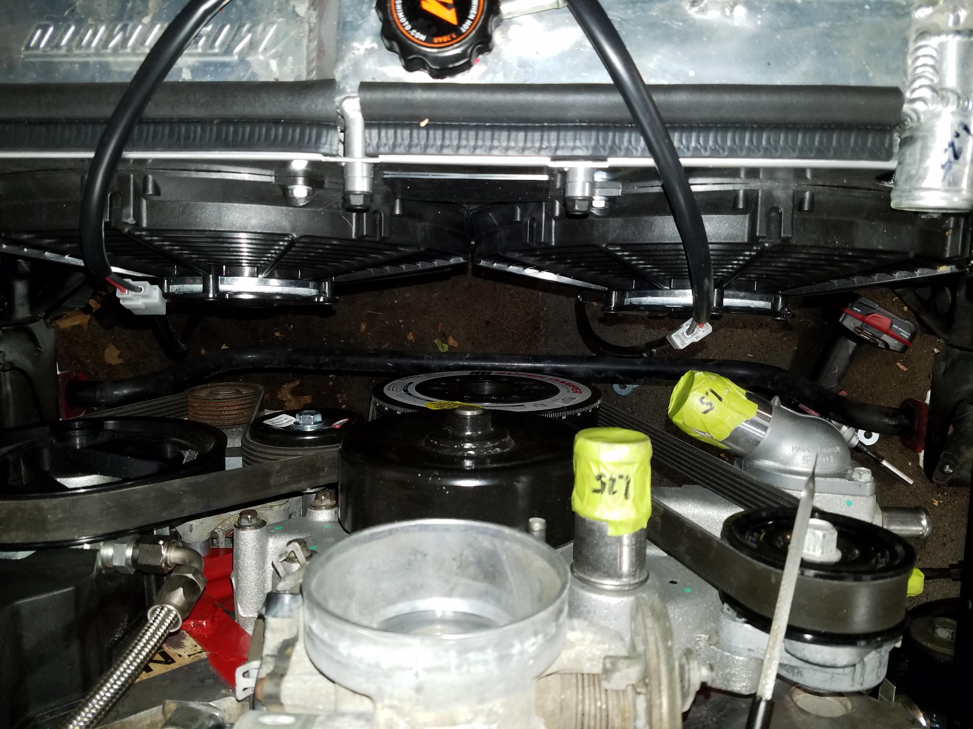
01-03-2017, 09:44 PM
#95
V8 Miata Enthusiast
Thread Starter
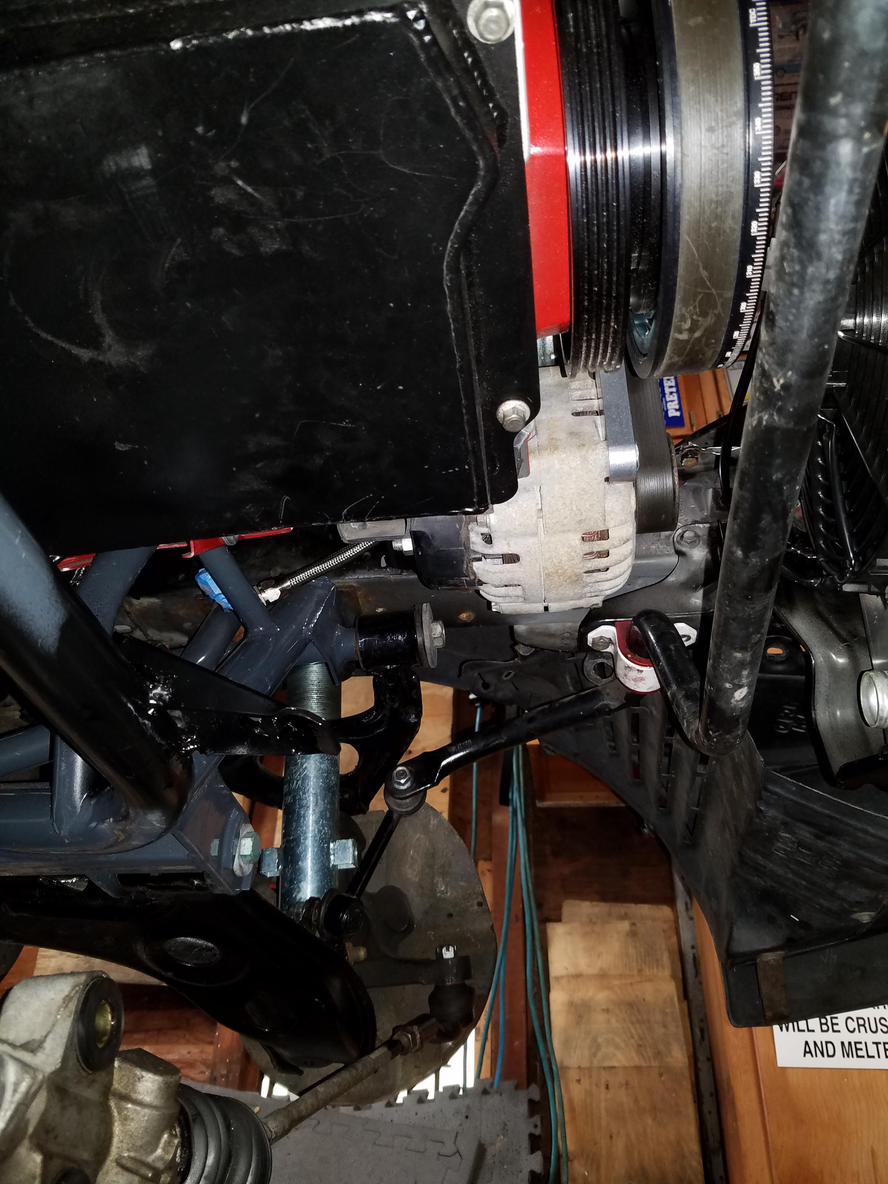
It was obvious the stock Miata swaybar will not clear the engine, so you can do a few things. Flyin Miata sells a bar that clears stuff, or you can make extensions to the swaybar mounts to move the bar lower. I bought the car with a pretty thick Racing Beat bar, over an inch thick. The car handles pretty flat which could be the bar doing it's job, so I was hesitant to give it up (I am keeping the bar, not selling yet). I also read that some people may have issues with swaybar mount extensions twisting or breaking unless they are made very beefy. Since this bar was stiff I was concerned that would be an issue. A broken swaybar mount in mid turn would be eventful.
I read on a post here https://forum.miata.net/vb/showthread.php?t=404786 that you can use an E36 BMW M3 bar with success, because it has a bump on the middle of the bar that clears the engine perfectly. The width from link to link also lines up with the Miata. Pretty cool I thought. If it worked, I could also upgrade to one of the many E36 BMW front swaybar options out there if I wanted something stiffer.
And then it hit me... literally... as I walked out of the garage. I have an E36 M3! While I did a coolant flush and brake line bleed on the BMW one day, I pulled the front bar out and had a look.
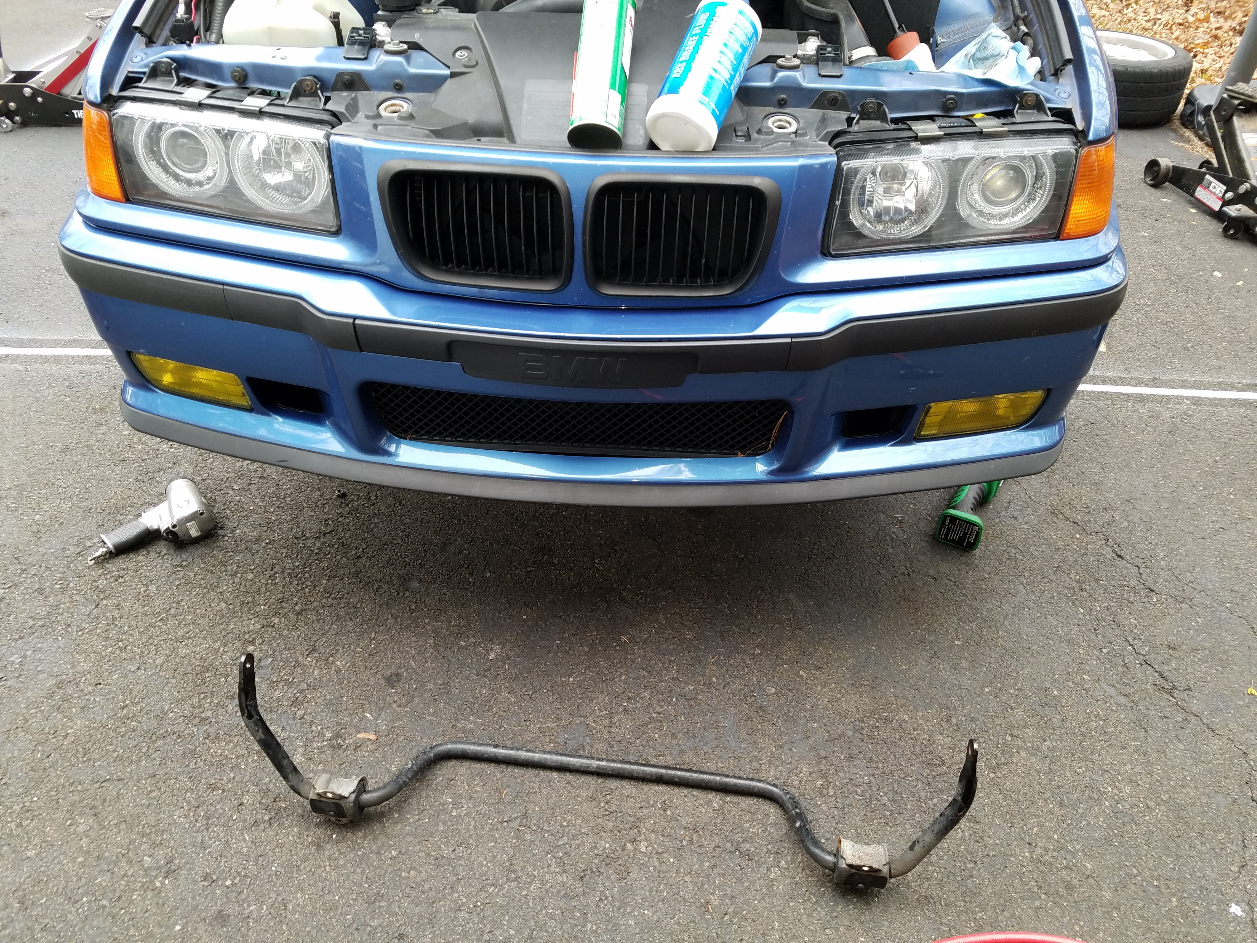
Long story short, hell yeah it will fit
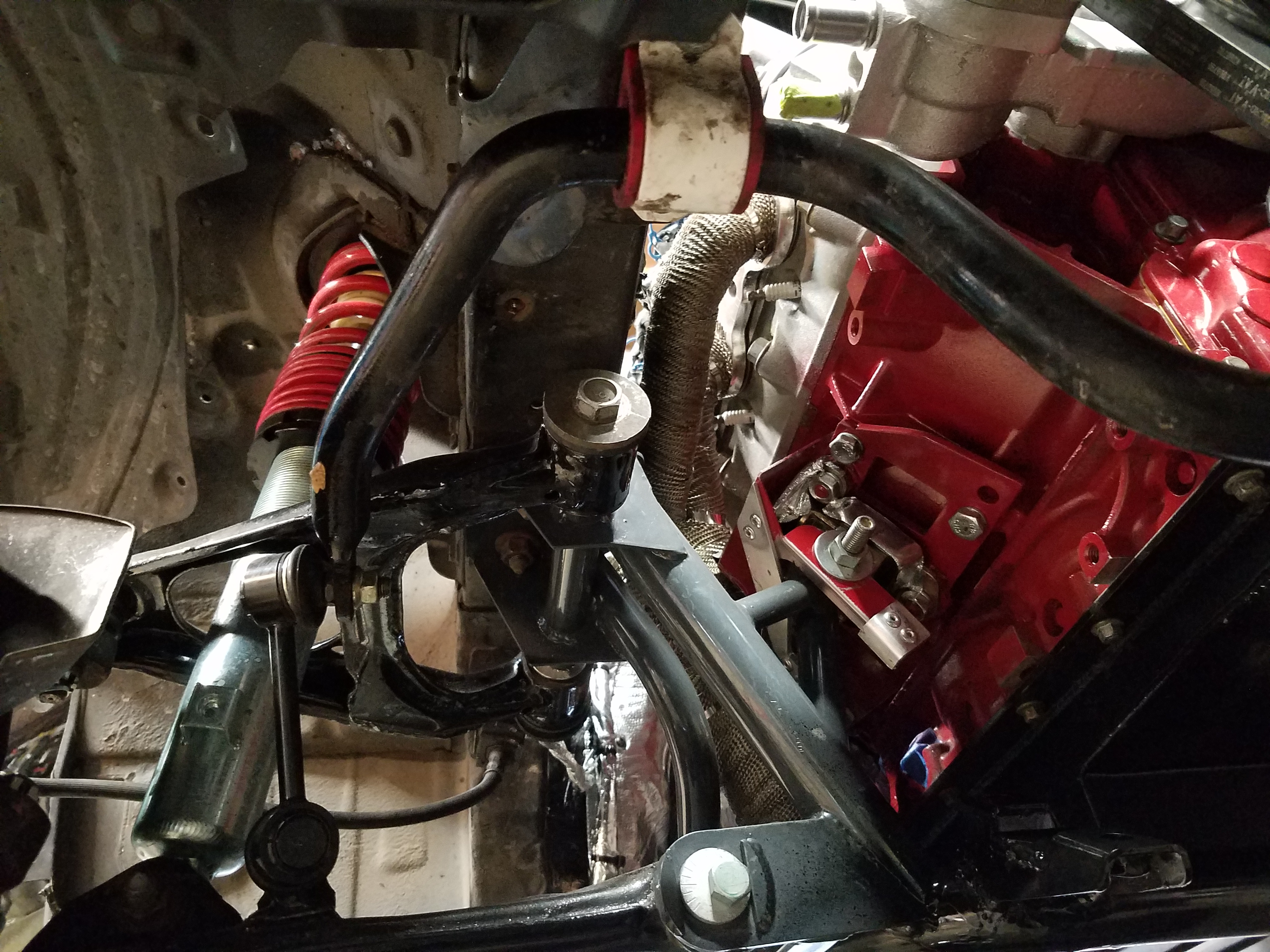
The stock links I was using are a bit long and out of plumb so figured I'd have to move the rack mounts back a bit to fix that.
Since I knew this would work I did a quick search on ebay and found a BMW used parts seller about 20 mins from me selling an M3 bar in good shape for a good price. I picked it up the next day and wire wheeled the rust off of it, and gave it a nice coat of paint.
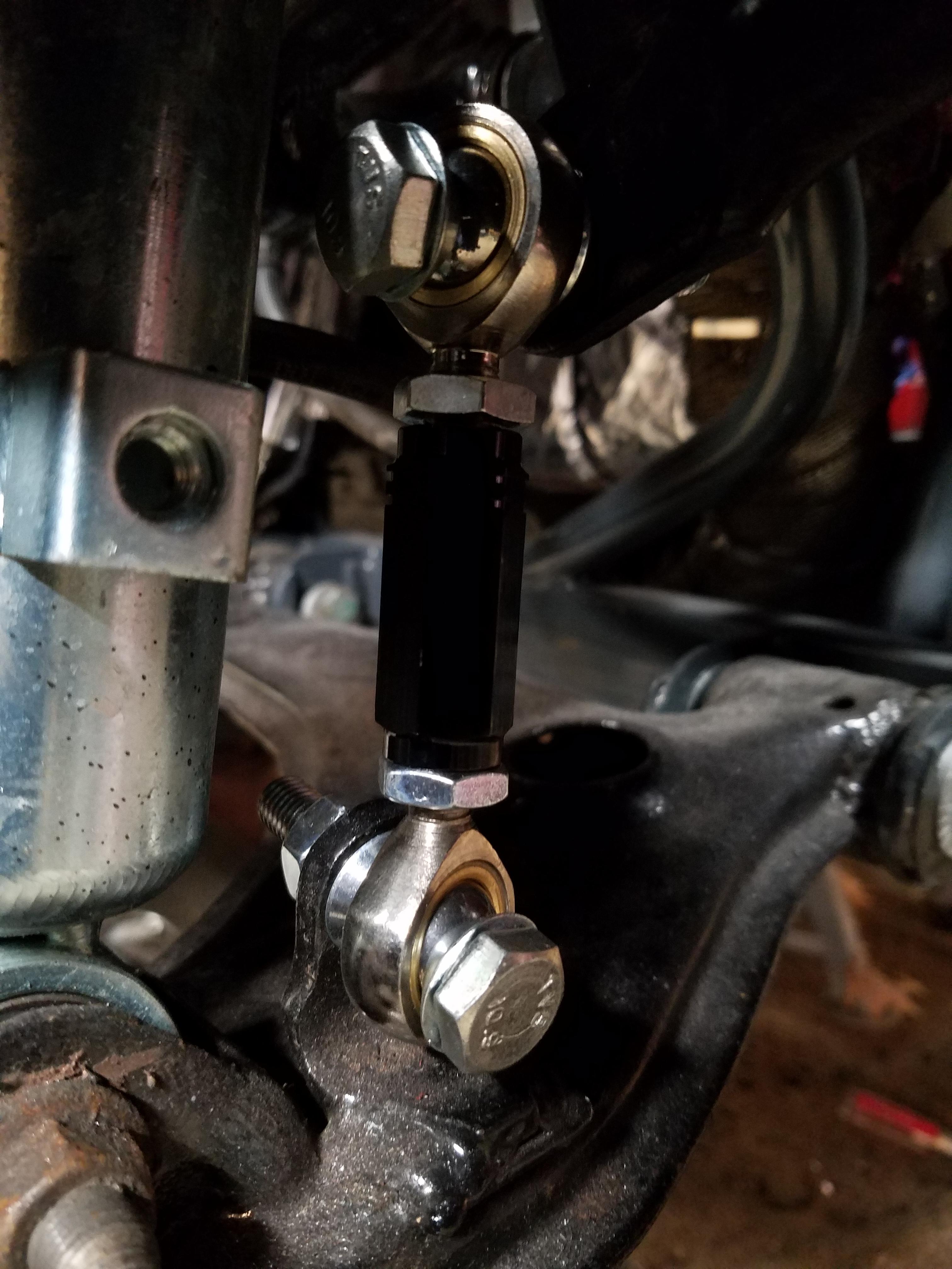
In the meantime I picked up some adjustable sway bar links from SuperMiata - SuperMiata End Links. They have a nice video that goes over the features of the links and the price seemed right.
I also picked up some poly swaybar bushings since the OEM BMW mounts are rubber. Energy Suspension luckily sells a variety of bushings for different diamater bars. energysuspension.com | Sway Bar & End Link Bushings
The BMW bar is something like 23mm, so I bought the correct bushing to match (can't recall which one).
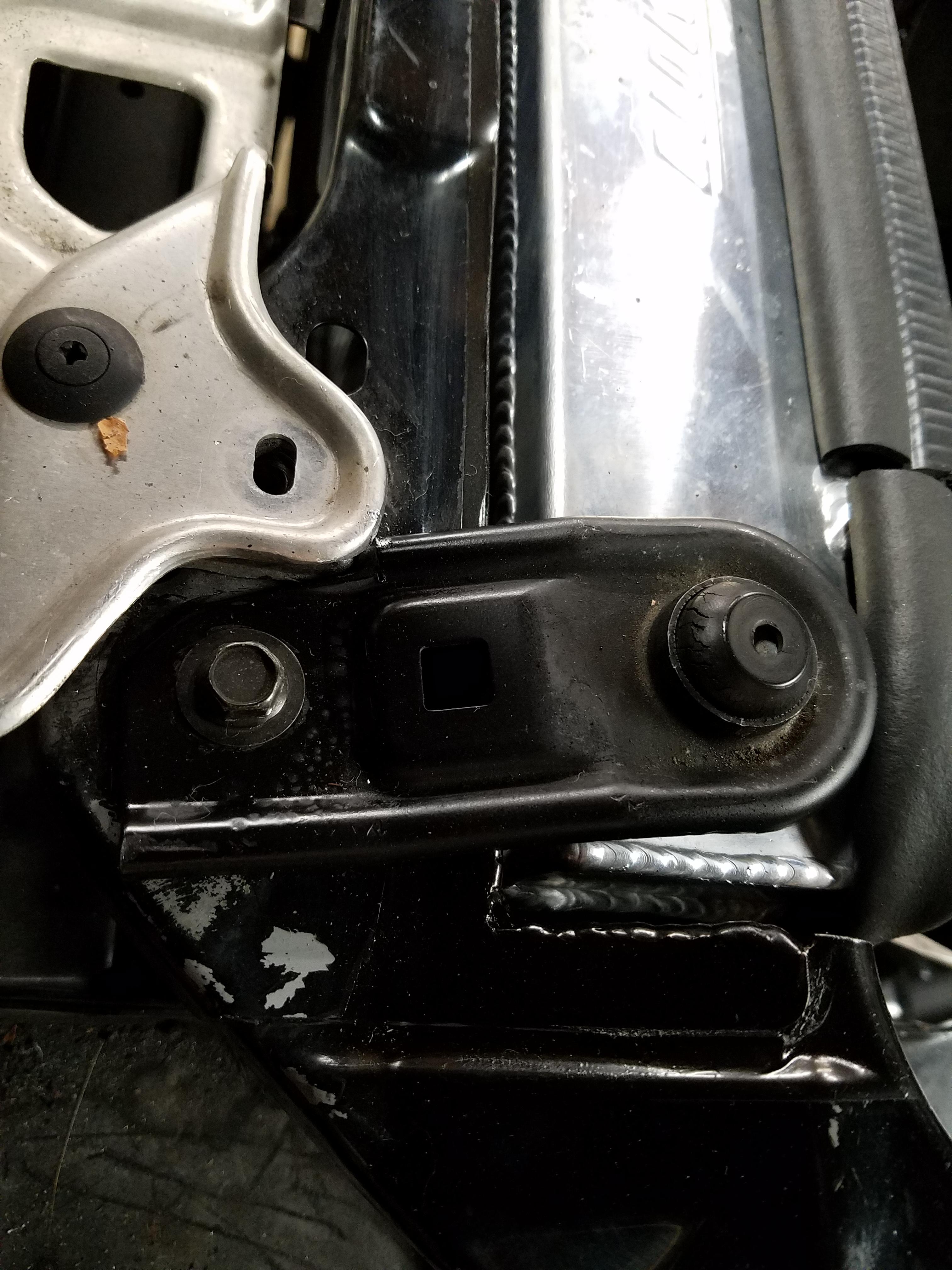
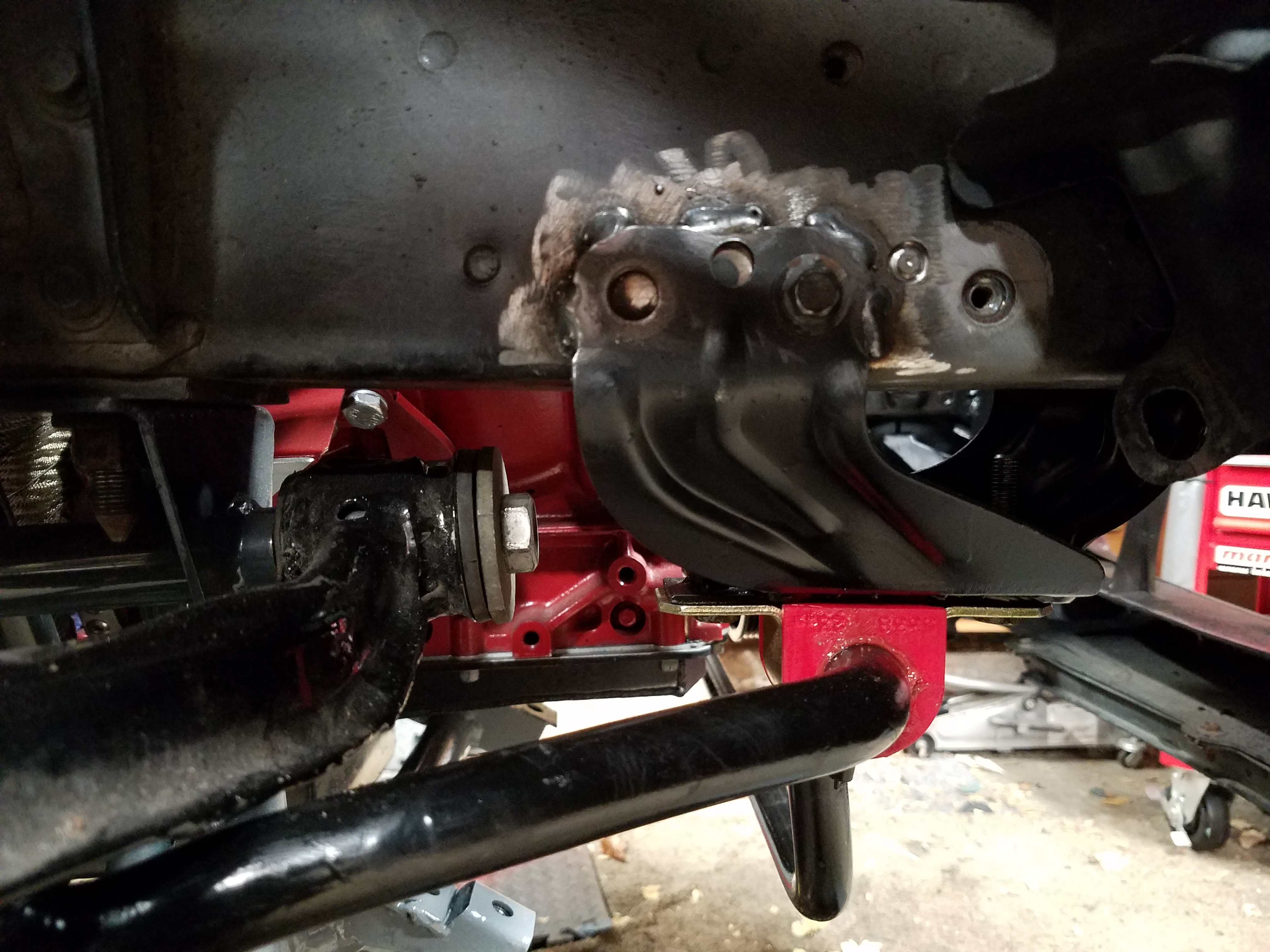
The bushing mounting bracket bolt spacing it a bit wider than the Miata bracket, so I welded on some extensions to the Miata brackets which bolt onto the frame rails. Welded some captive nuts at the right spacing.
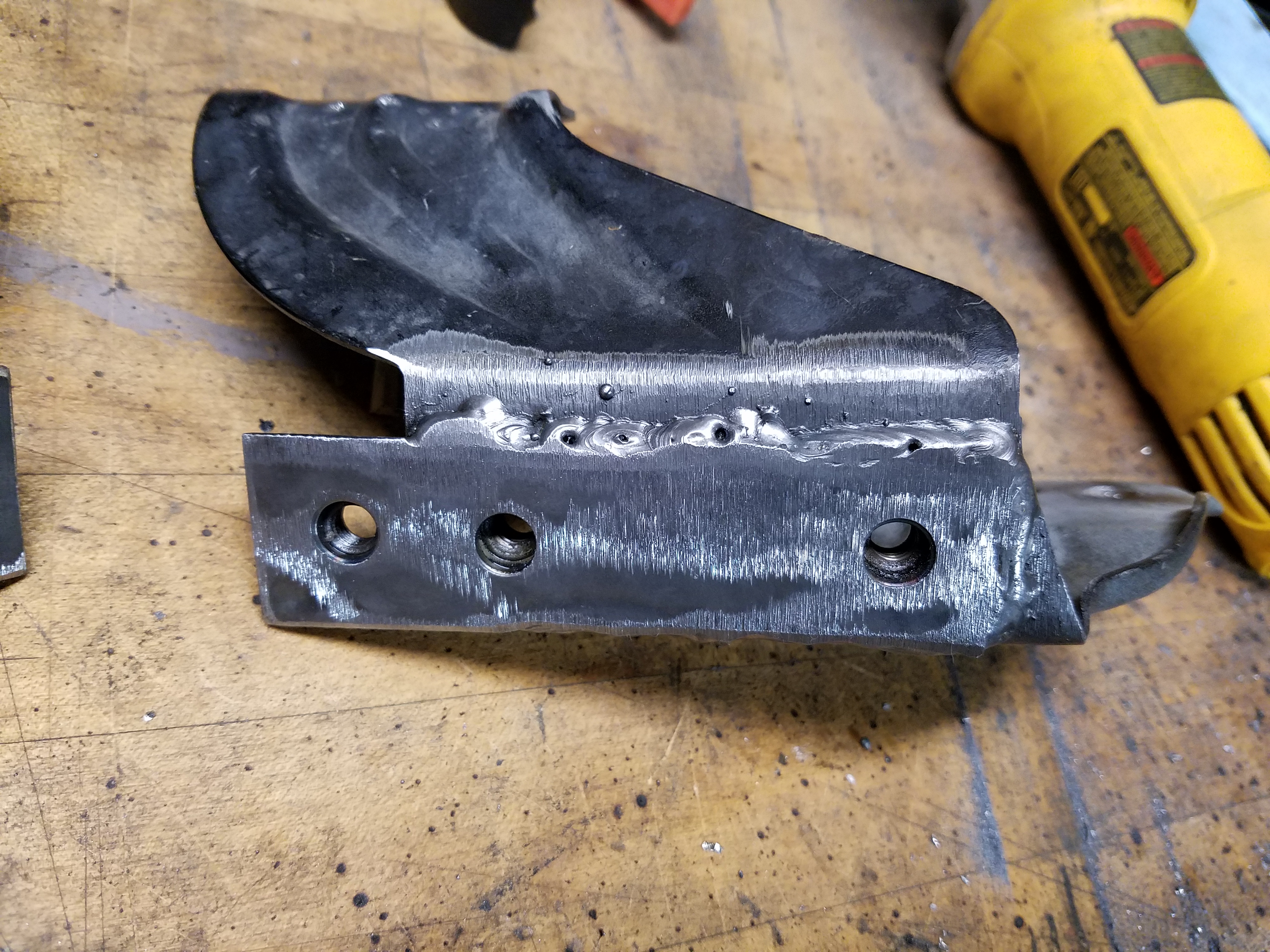
Did some rough mounting on the car. You can see where the Miata bracket front mounting bolt lines up with the rear bolt hole on the frame rail. This turned out to work fine for moving the mount back enough for the end links to be happy. Once I was happy I welded them in and gave them a good coat of paint.
As they say, Happy endlinks, Happy life
That about completes some of the fabrication stuff needed in the engine bay. With everything in place and painted, I was able to move onto other tasks.
I read on a post here https://forum.miata.net/vb/showthread.php?t=404786 that you can use an E36 BMW M3 bar with success, because it has a bump on the middle of the bar that clears the engine perfectly. The width from link to link also lines up with the Miata. Pretty cool I thought. If it worked, I could also upgrade to one of the many E36 BMW front swaybar options out there if I wanted something stiffer.
And then it hit me... literally... as I walked out of the garage. I have an E36 M3! While I did a coolant flush and brake line bleed on the BMW one day, I pulled the front bar out and had a look.
Long story short, hell yeah it will fit
The stock links I was using are a bit long and out of plumb so figured I'd have to move the rack mounts back a bit to fix that.
Since I knew this would work I did a quick search on ebay and found a BMW used parts seller about 20 mins from me selling an M3 bar in good shape for a good price. I picked it up the next day and wire wheeled the rust off of it, and gave it a nice coat of paint.
In the meantime I picked up some adjustable sway bar links from SuperMiata - SuperMiata End Links. They have a nice video that goes over the features of the links and the price seemed right.
I also picked up some poly swaybar bushings since the OEM BMW mounts are rubber. Energy Suspension luckily sells a variety of bushings for different diamater bars. energysuspension.com | Sway Bar & End Link Bushings
The BMW bar is something like 23mm, so I bought the correct bushing to match (can't recall which one).
The bushing mounting bracket bolt spacing it a bit wider than the Miata bracket, so I welded on some extensions to the Miata brackets which bolt onto the frame rails. Welded some captive nuts at the right spacing.
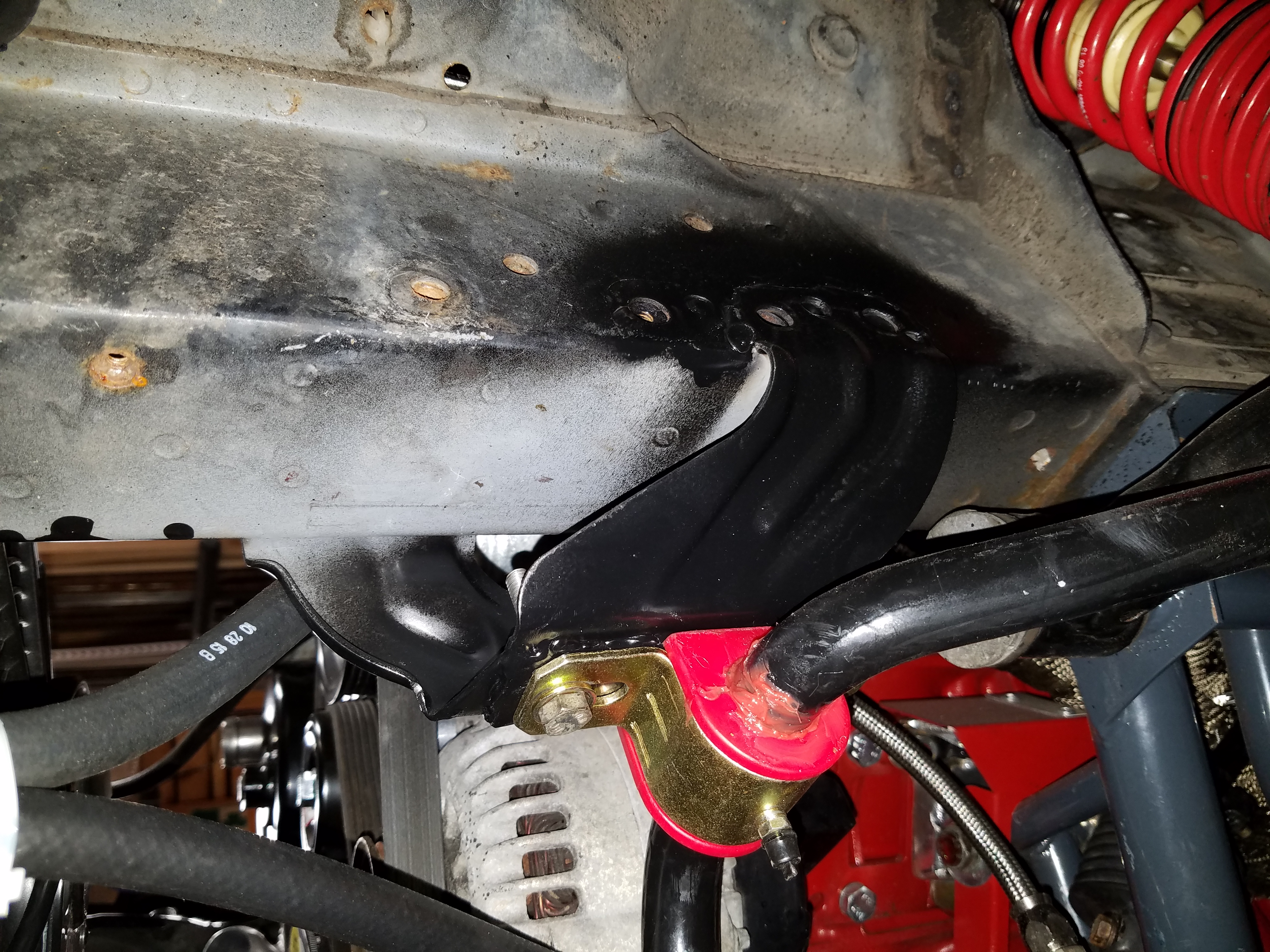
Did some rough mounting on the car. You can see where the Miata bracket front mounting bolt lines up with the rear bolt hole on the frame rail. This turned out to work fine for moving the mount back enough for the end links to be happy. Once I was happy I welded them in and gave them a good coat of paint.
As they say, Happy endlinks, Happy life
That about completes some of the fabrication stuff needed in the engine bay. With everything in place and painted, I was able to move onto other tasks.
Last edited by pj_mcgarvey; 01-04-2017 at 06:48 AM.
The following users liked this post:
Viriiguy (01-25-2017)
01-03-2017, 10:03 PM
#96
V8 Miata Enthusiast
Thread Starter
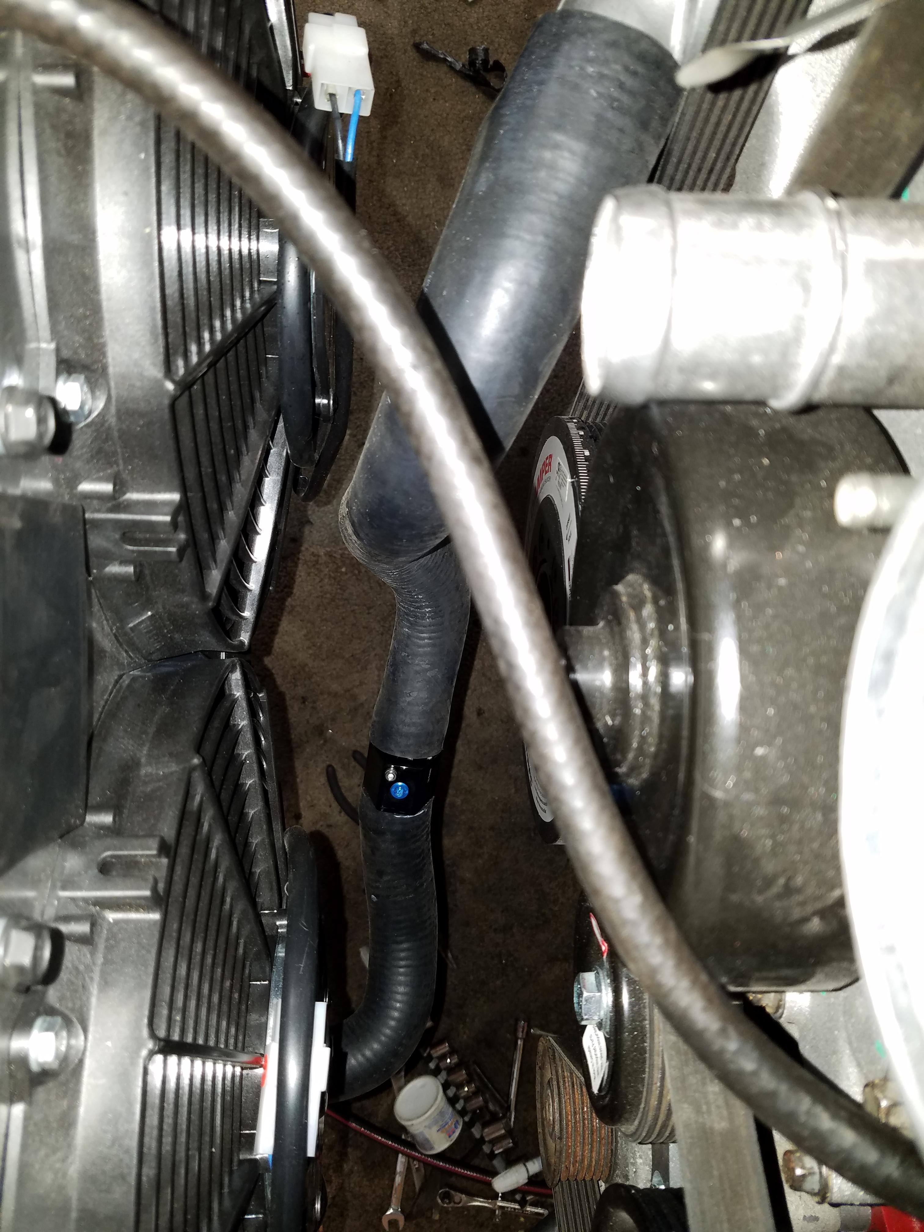
As I was getting the rad mounted I was planning my attack on routing the hoses. I took measurements of the hose flange sizes on the GM water pump and Miata radiator I had and some approx. measurements of how much hose I needed and bends.
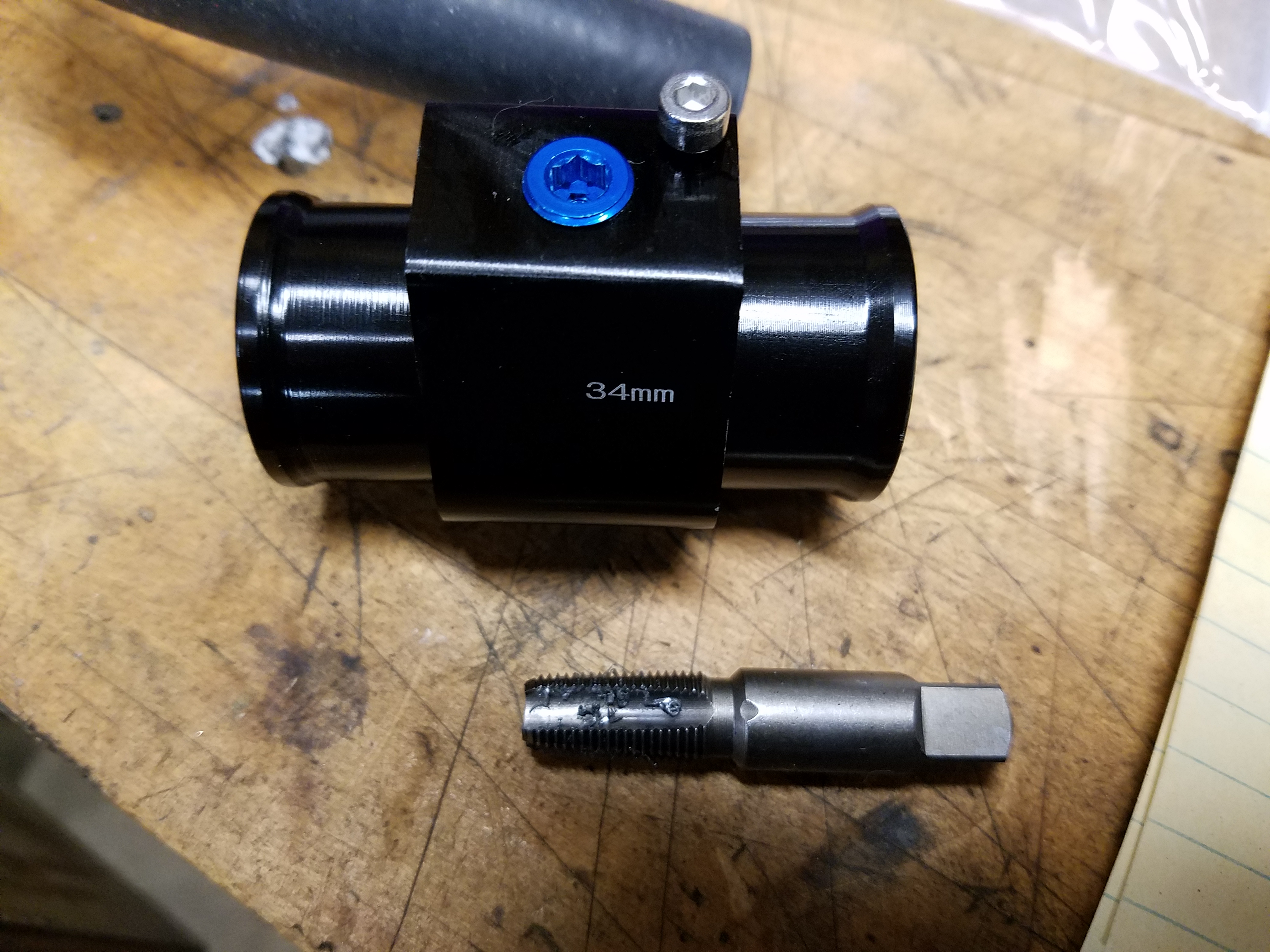
Using some info from these forums I figured both upper and lower rad hoses would need to be spliced together so I found these on Amazon https://www.amazon.com/gp/product/B018FY0Z84 You'll also need these little 1/8" NPT plugs in case you don't use the ports for anything else https://www.amazon.com/gp/product/B000CIM3GO
Because even little plugs can't be easy, I found out the threads were a little rough. After almost stripping one and ruining a plug, I picked up a cheap ebay NPT tap and cleaned them out. You can see the amount of trash the threads have.
Turns out Jegs.com has good info on a bunch of hoses, including pictures, diameters of the hose ends, length, etc.
For the upper hose I picked up a Gates 22029 hose https://www.amazon.com/gp/product/B000C2SAVC which was detailed here by Jegs http://www.jegs.com/i/Gates/465/22029/10002/-1
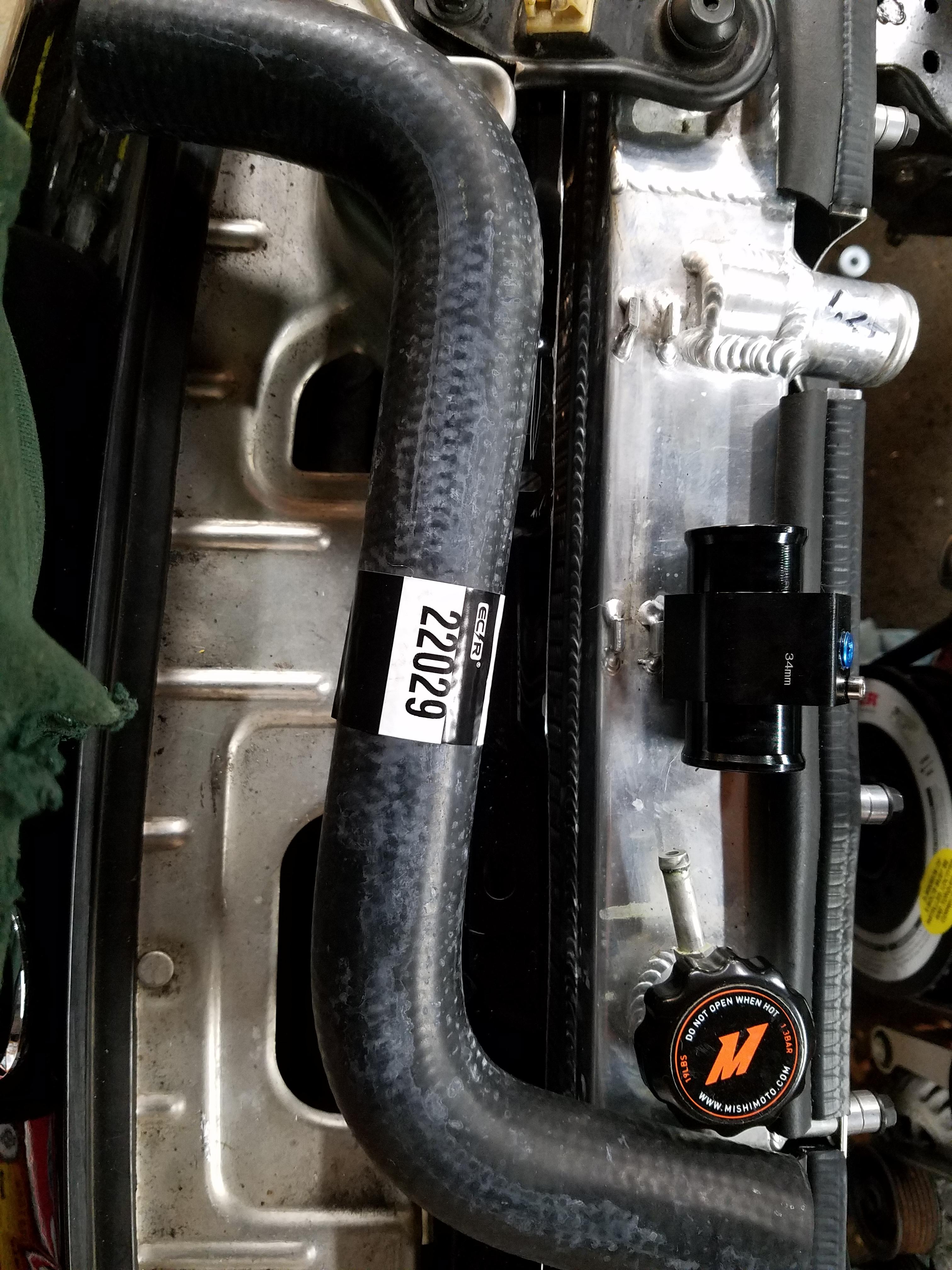
This would just get shortened in the middle to the right size (depending on your application) and the hose coupling would do the rest.
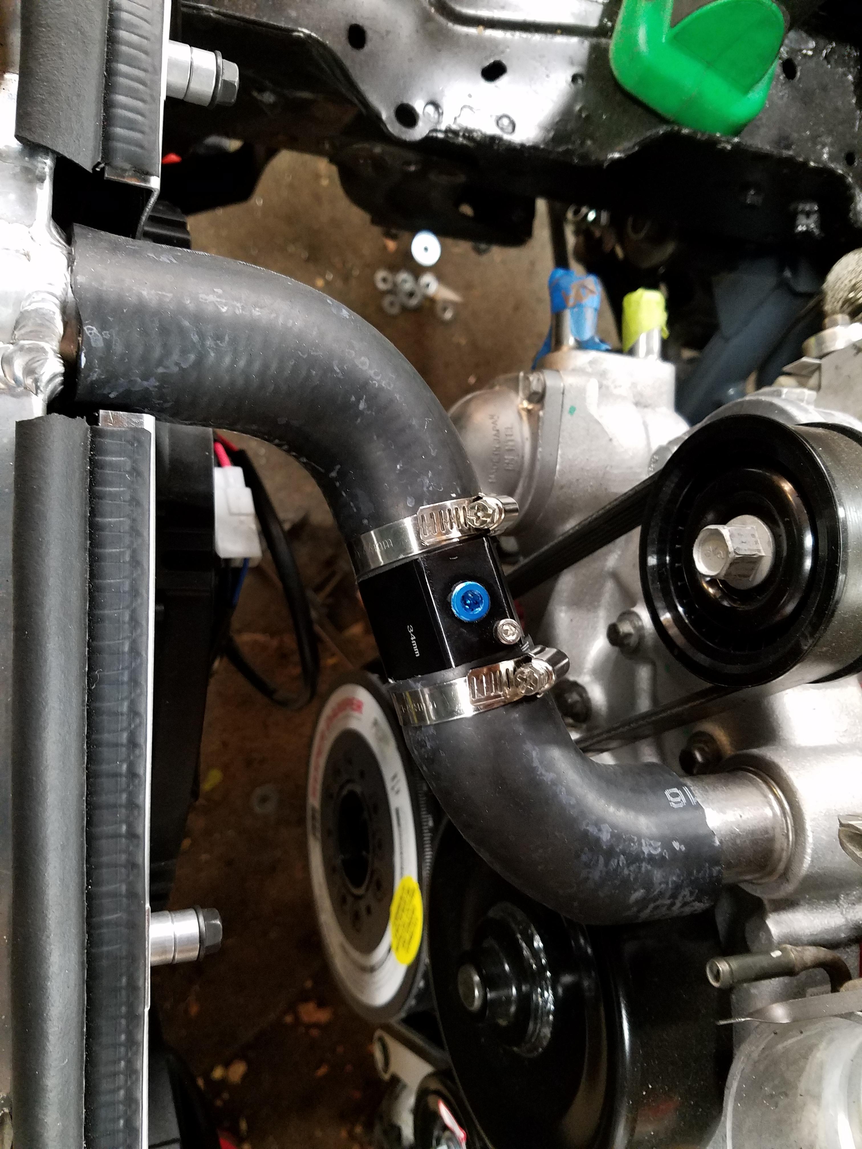
A Gates 22373 hose would get me most of the way for the lower rad hose. I actually bought two of these since I figured all the bends on this one would get me the length I needed. https://www.amazon.com/gp/product/B000C2WDFQ
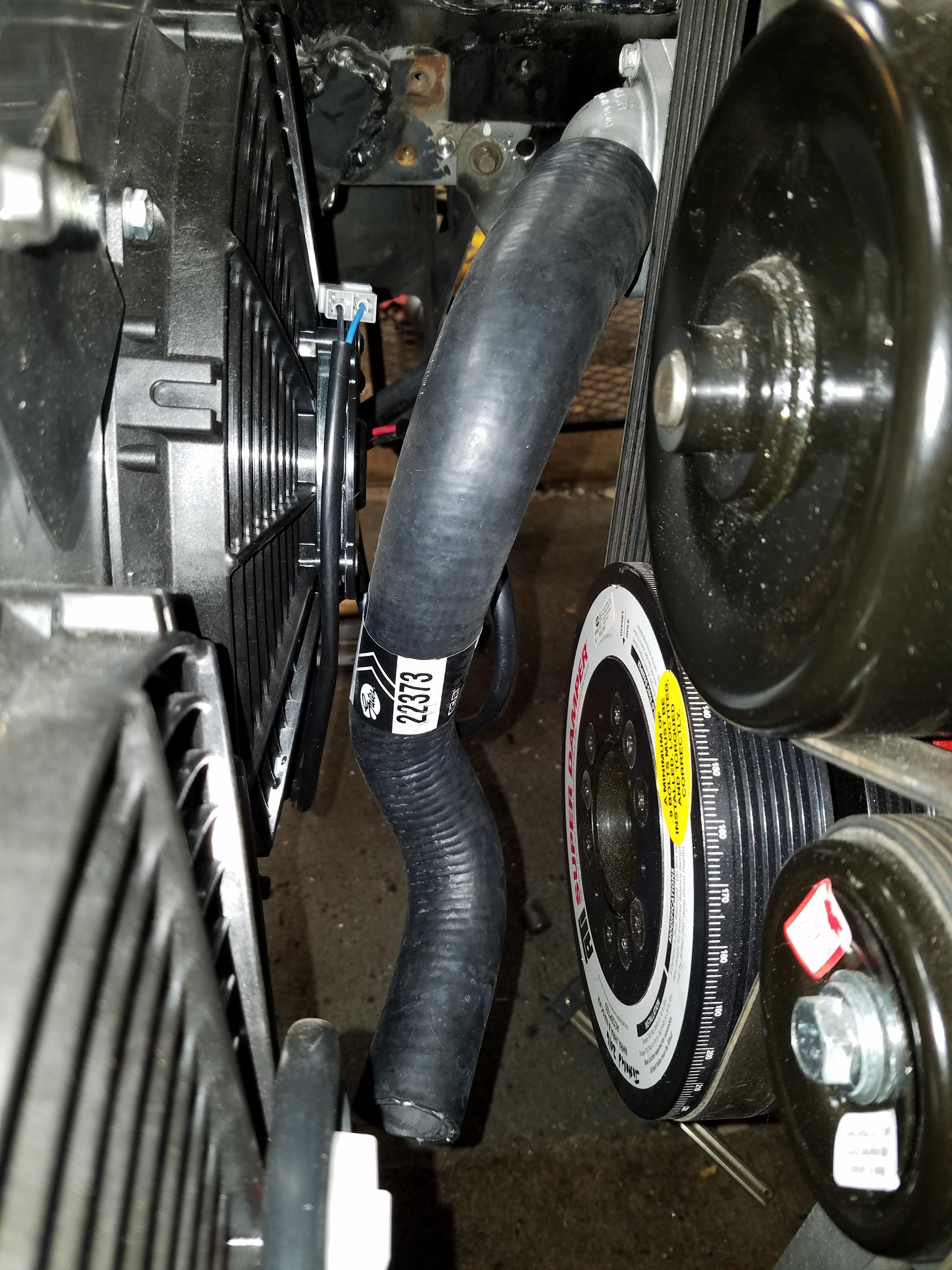
I'm pretty happy with the way this turned out. Hose clamps were added later.
I'll go over the heater hose connections once I have the engine harness in. But I can say now the heater hookup may work out even better then the rad hoses for the OEM look and feel.
Using some info from these forums I figured both upper and lower rad hoses would need to be spliced together so I found these on Amazon https://www.amazon.com/gp/product/B018FY0Z84 You'll also need these little 1/8" NPT plugs in case you don't use the ports for anything else https://www.amazon.com/gp/product/B000CIM3GO
Because even little plugs can't be easy, I found out the threads were a little rough. After almost stripping one and ruining a plug, I picked up a cheap ebay NPT tap and cleaned them out. You can see the amount of trash the threads have.
Turns out Jegs.com has good info on a bunch of hoses, including pictures, diameters of the hose ends, length, etc.
For the upper hose I picked up a Gates 22029 hose https://www.amazon.com/gp/product/B000C2SAVC which was detailed here by Jegs http://www.jegs.com/i/Gates/465/22029/10002/-1
This would just get shortened in the middle to the right size (depending on your application) and the hose coupling would do the rest.
A Gates 22373 hose would get me most of the way for the lower rad hose. I actually bought two of these since I figured all the bends on this one would get me the length I needed. https://www.amazon.com/gp/product/B000C2WDFQ
I'm pretty happy with the way this turned out. Hose clamps were added later.
I'll go over the heater hose connections once I have the engine harness in. But I can say now the heater hookup may work out even better then the rad hoses for the OEM look and feel.
Last edited by pj_mcgarvey; 01-04-2017 at 06:56 AM.
The following users liked this post:
Viriiguy (01-25-2017)
01-03-2017, 10:18 PM
#97
V8 Miata Enthusiast
Thread Starter
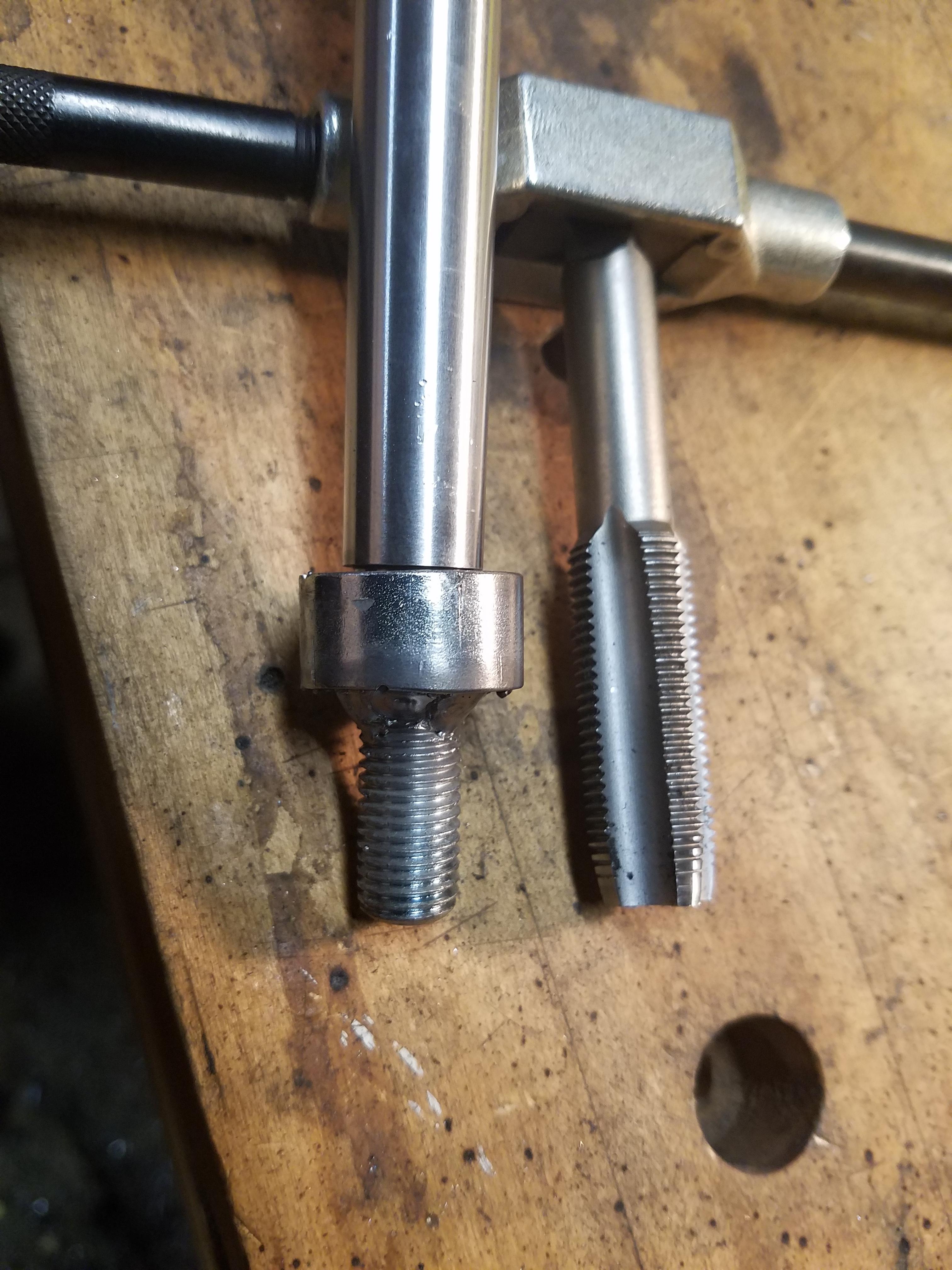
In the meantime I also did some custom work on the shifter to make my Golf ball shift **** work. This rubber golf ball shift **** has been on 3 different cars over probably 15 years, from my 98 Golf VR6, to my 85 Golf to the Miata. I made a custom adapter for the oem Miata shifter and figured I'd do the same for the T56 shifter.
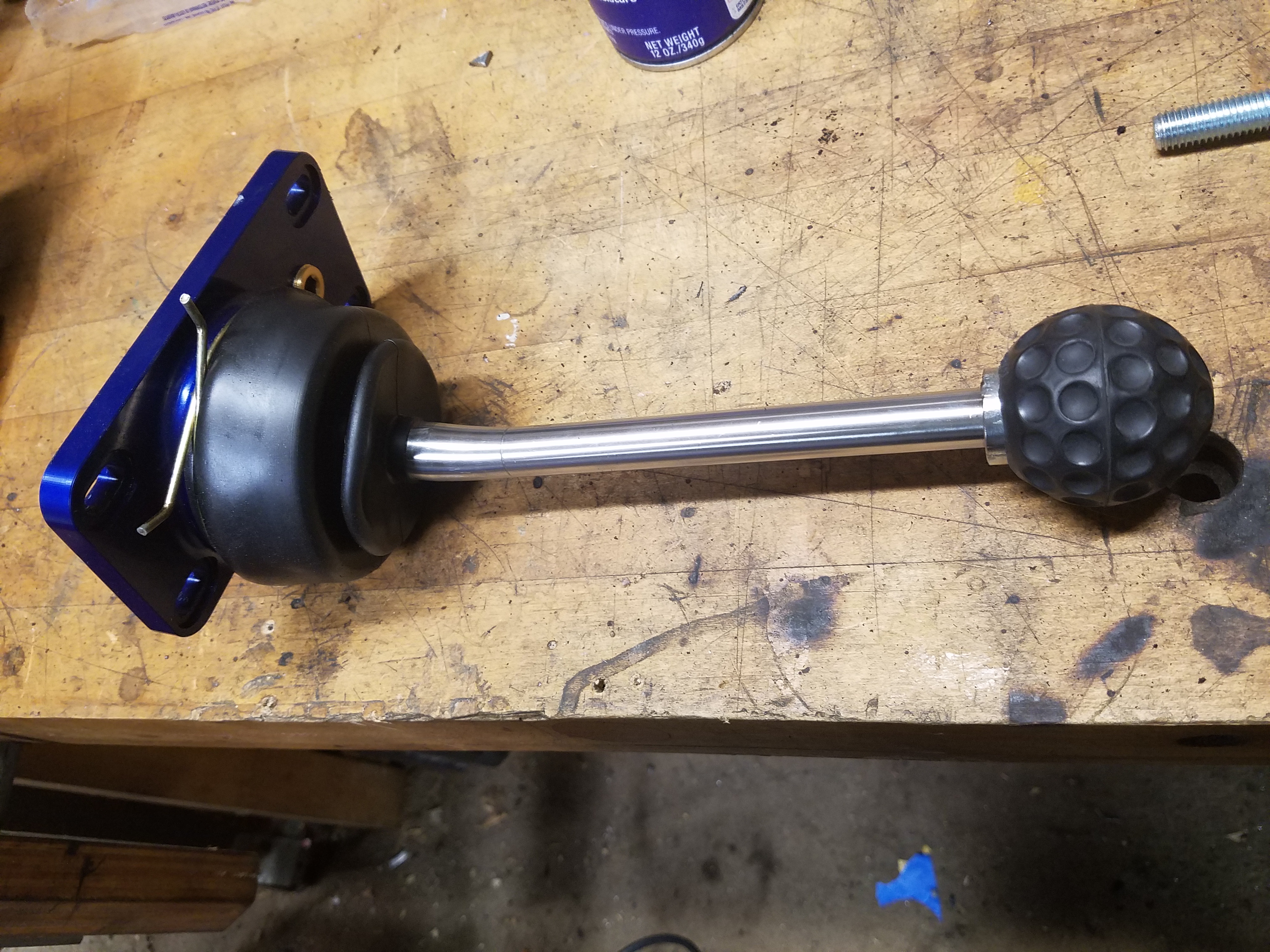
I also expanded my ever growing collection of random size tap and dies
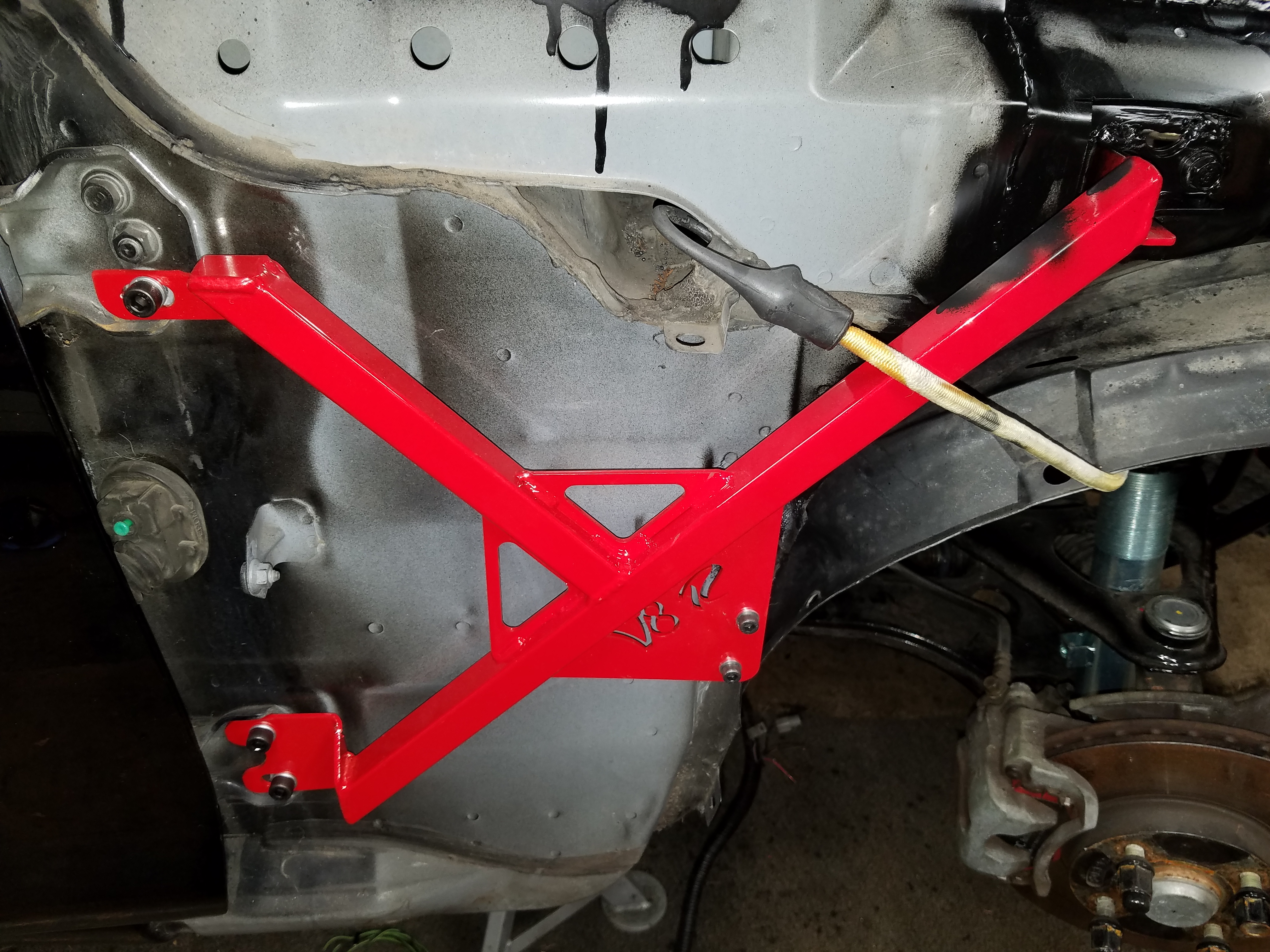
Installed the V8 Roadsters chassis side brace as well. Instructions were a bit sparse on these, but it was easy to figure out.
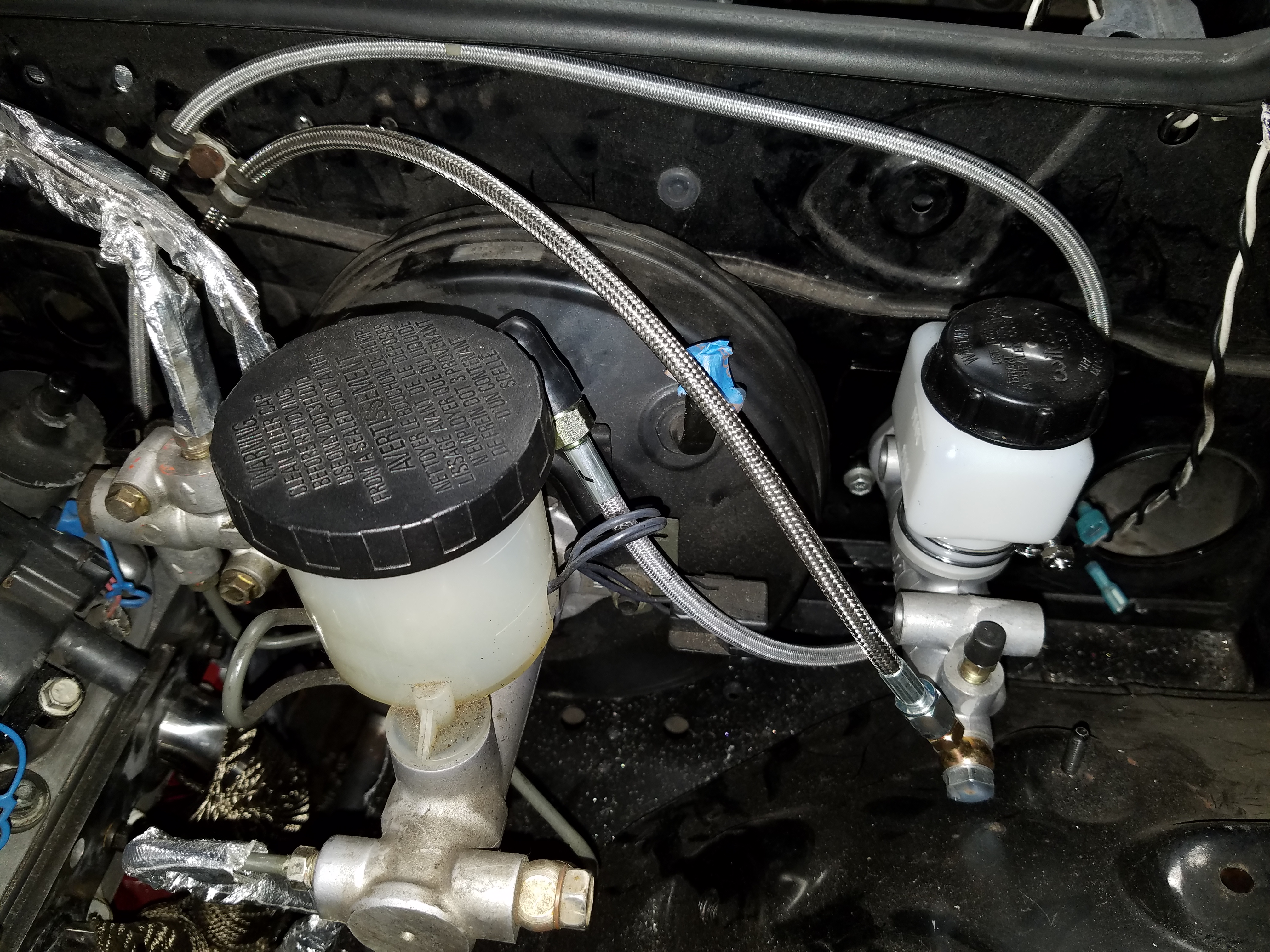
Clutch line is routed and installed, with another conveniently placed bolt hole to keep the lines in place up against the firewall
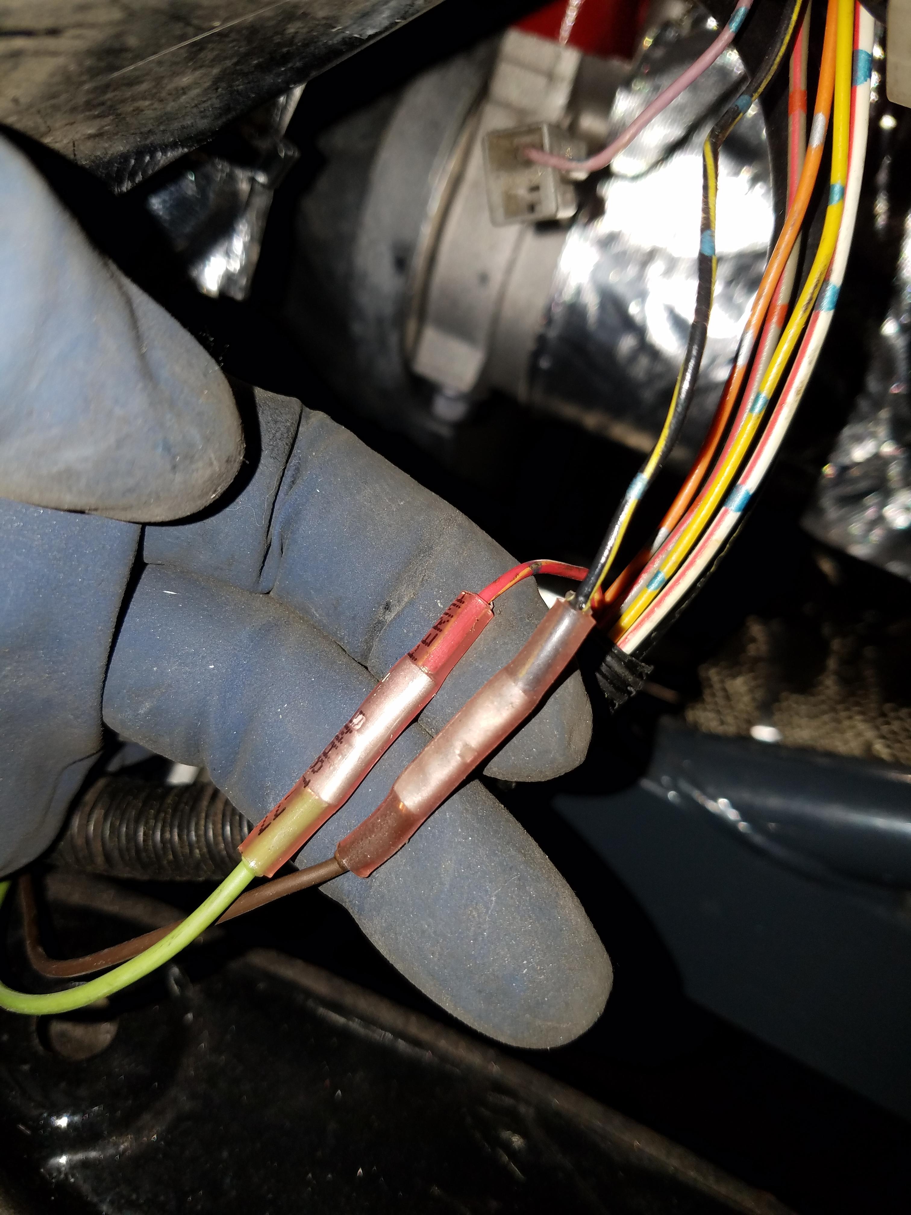
I've started working on the wiring as well. Getting the under car harness routed back up to the engine bay. I just ran the harness tight with the fuel and brake lines. As it peeks out in the wheel well there are two wires you can connect to the T56 reverse light switch. The bottom wires are the T56 switch connector which you just separate from the main engine harness. The upper wires Black/Yellow and Red/Yellow are connected to the switch wires in no particular polarity. The Flyin Miata wiring guide goes over this depending on the year of your car.
I'll be going over the rest of the wiring for the starter, alternator once that's done. Hopefully I can move onto mounting the Miata main harness and then lay out the LS1 engine harness and PCM.
Summit Racing 2.5" exhaust kit is waiting patiently in the wings in case I need a distraction from wiring.
I also expanded my ever growing collection of random size tap and dies
Installed the V8 Roadsters chassis side brace as well. Instructions were a bit sparse on these, but it was easy to figure out.
Clutch line is routed and installed, with another conveniently placed bolt hole to keep the lines in place up against the firewall
I've started working on the wiring as well. Getting the under car harness routed back up to the engine bay. I just ran the harness tight with the fuel and brake lines. As it peeks out in the wheel well there are two wires you can connect to the T56 reverse light switch. The bottom wires are the T56 switch connector which you just separate from the main engine harness. The upper wires Black/Yellow and Red/Yellow are connected to the switch wires in no particular polarity. The Flyin Miata wiring guide goes over this depending on the year of your car.
I'll be going over the rest of the wiring for the starter, alternator once that's done. Hopefully I can move onto mounting the Miata main harness and then lay out the LS1 engine harness and PCM.
Summit Racing 2.5" exhaust kit is waiting patiently in the wings in case I need a distraction from wiring.
 01-12-2017, 08:23 AM
#99
V8 Miata Enthusiast
Thread Starter
01-13-2017, 02:34 PM
#100
V8 Miata Enthusiast
Thread Starter
Mounted the Miata thick white alternator wire to the GM alternator stud on the back. Was able to use the existing ring terminal and plastic cover. Not a perfect fit as the wire comes out the side vs. coming out the top.
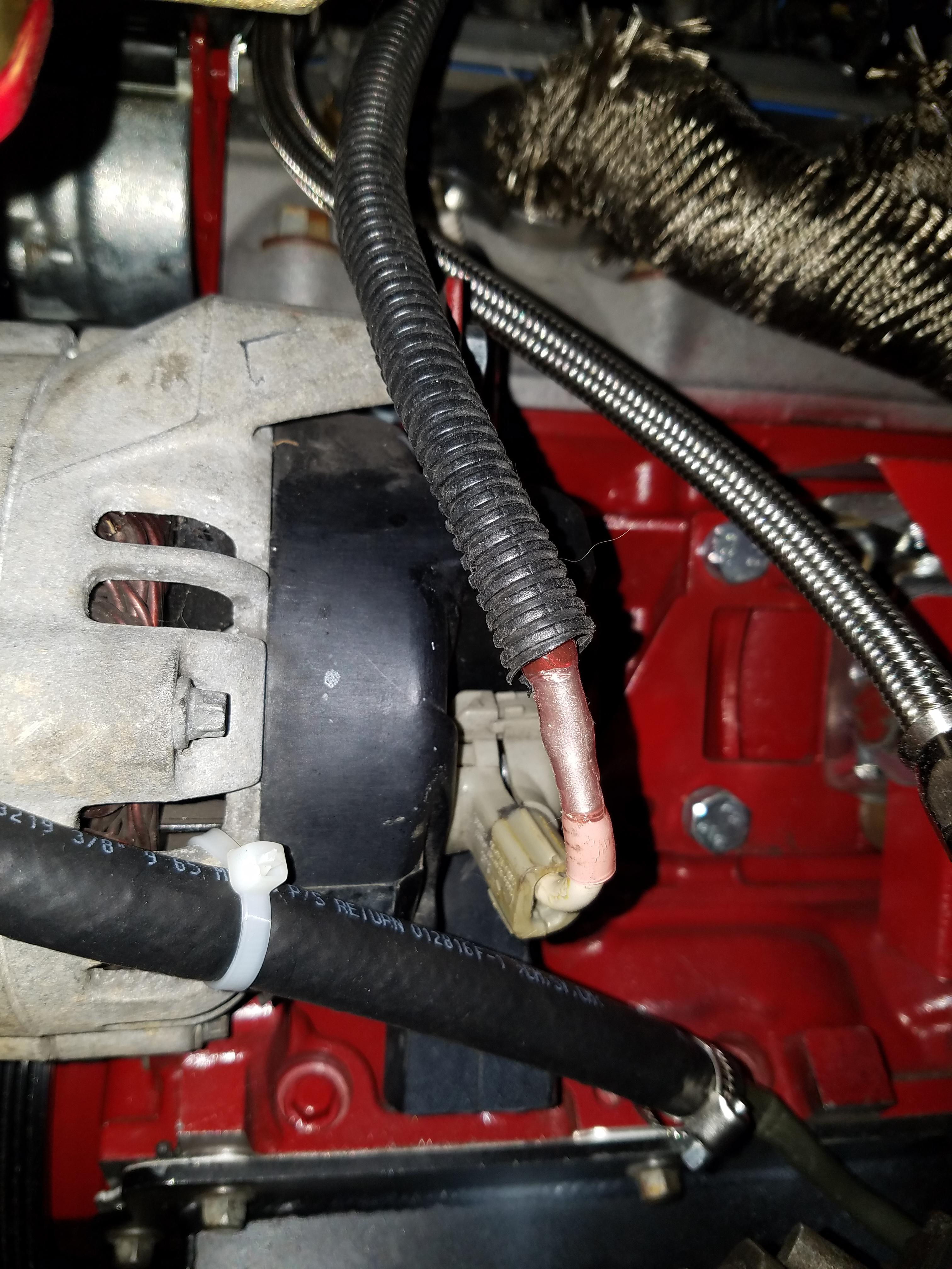
I ran the white wire up along the frame rail on the driver's side, and then along the firewall zip tied to where the brake lines run. Covered in plastic loom. Other alternator connections will come later.
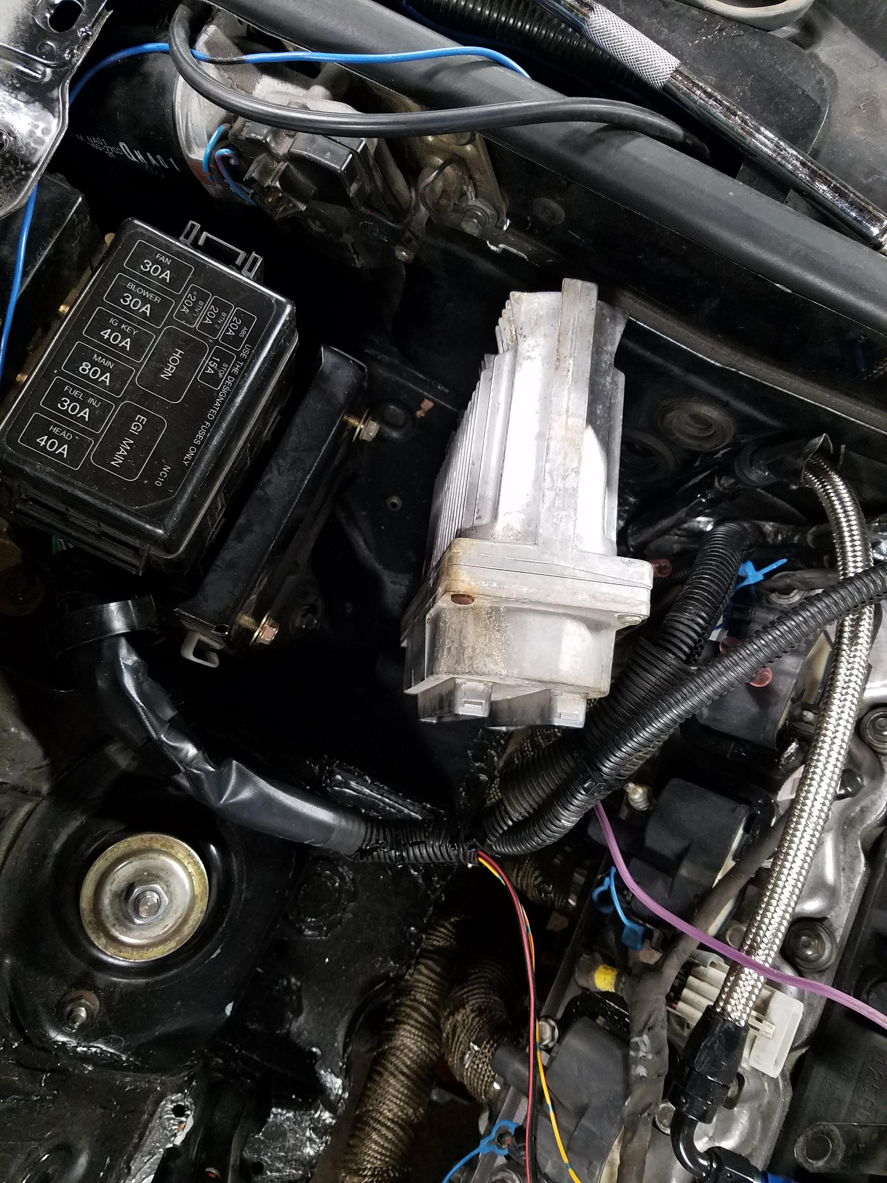
Decided to go with mounting the PCM in the "engine room" vs the cabin. The 98 LS1 PCM is pretty bulky but there is room for it, and maybe some add'l room for me to hook up A/C lines at some point in the future. Takes up less room mounted this way.
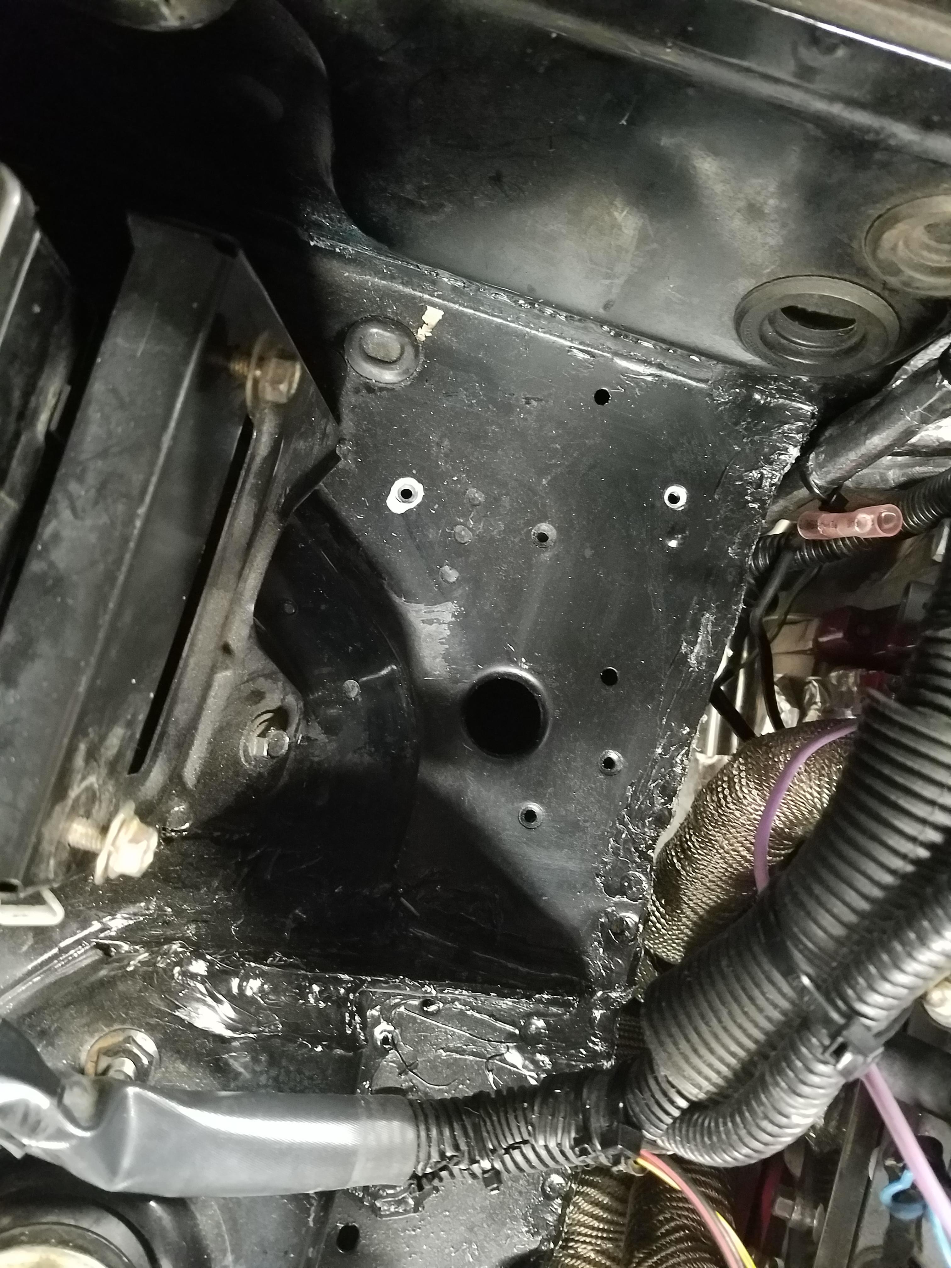
There are two conveniently located threaded holes in the body (I've marked in white paint pen) that I used to mount my bracket.
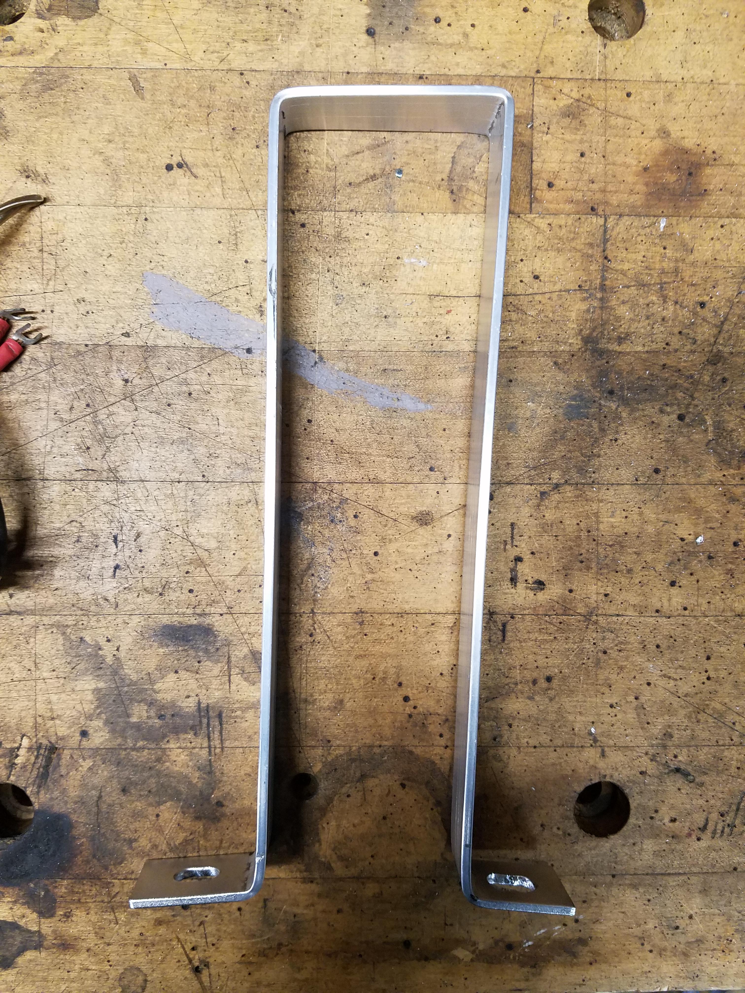
Here's my aluminum strap bracket
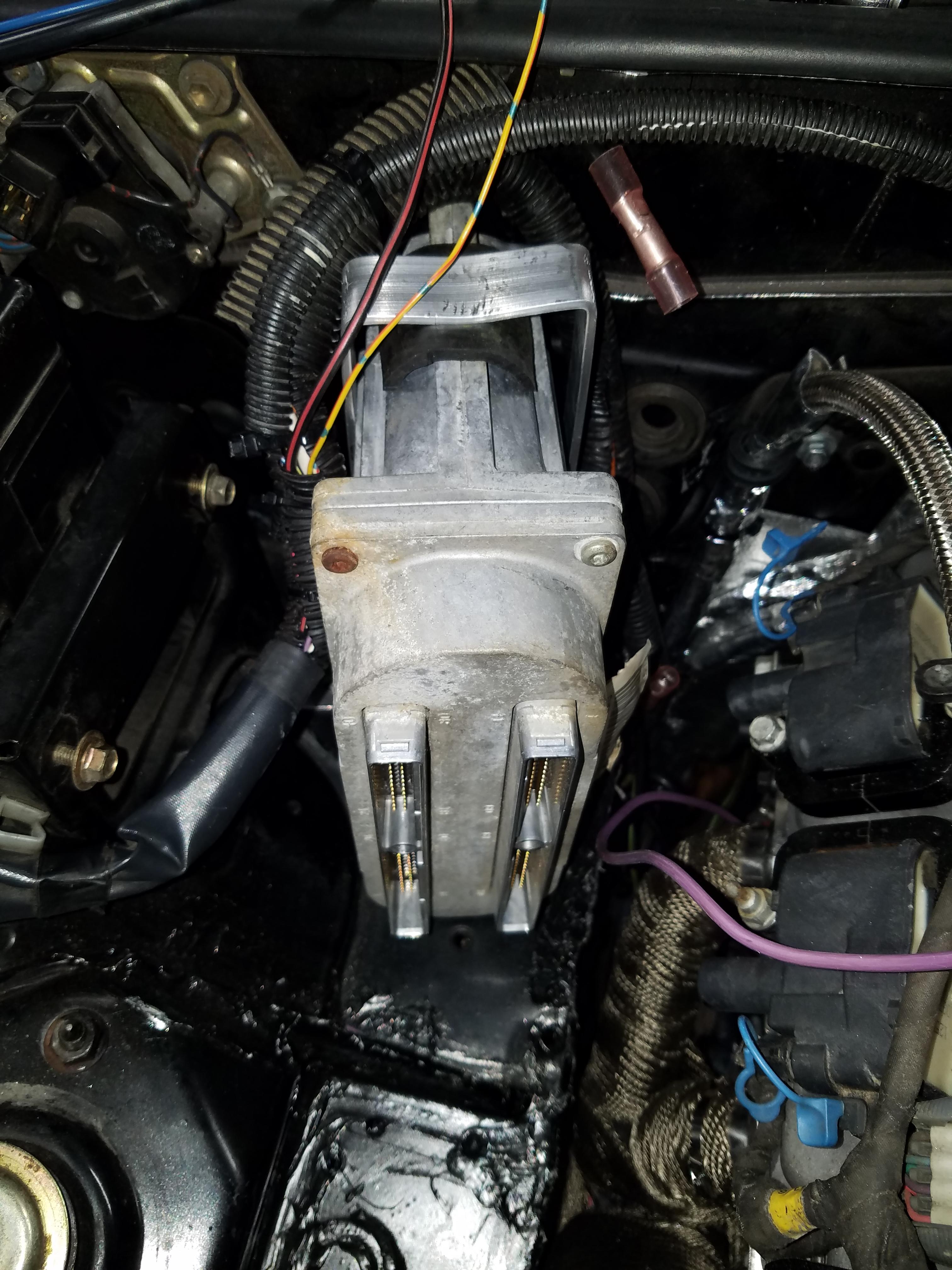
Bracket mounted tight. Squeeze the bracket a bit to bring it tight to the PCM, added a bit of old rubber hose as a cushion.
I ran the white wire up along the frame rail on the driver's side, and then along the firewall zip tied to where the brake lines run. Covered in plastic loom. Other alternator connections will come later.
Decided to go with mounting the PCM in the "engine room" vs the cabin. The 98 LS1 PCM is pretty bulky but there is room for it, and maybe some add'l room for me to hook up A/C lines at some point in the future. Takes up less room mounted this way.
There are two conveniently located threaded holes in the body (I've marked in white paint pen) that I used to mount my bracket.
Here's my aluminum strap bracket
Bracket mounted tight. Squeeze the bracket a bit to bring it tight to the PCM, added a bit of old rubber hose as a cushion.


