pj_mcgarvey's - LS1/T56 NB build thread

 10-25-2016, 04:37 PM
#51
V8 Miata Enthusiast
Thread Starter

Hehe, well, once you open the tube it's pretty quick setting stuff, so I figured use it or lose it!
Thank you for getting that joke. It means alot.
Test fitted and hope I'll be OK with headers fitted. I eyeballed everything with the just engine and bell installed and I think I should be good. The only thing I can't be too sure of is the gas pedal, but I can beat things back if I need to. I will likely know in a few days if things fit.
Thanks. Now where is that Ibuprofen...
Thank you for getting that joke. It means alot.
Did you do a test fit with engine/subframe, header etc before you finished up everything on the tunnel/firewall?? I know thats come back to bite some people in the *** later on. Gas pedal clearance on the drivers side, passengerside head to firewall clearance, and clearance of bellhousing bolts to trans tunnel are all important to look at.
Thanks. Now where is that Ibuprofen...
 10-26-2016, 08:13 AM
#52
V8 Miata Enthusiast
Thread Starter
***I found my part, so no need to contact me if you have one***
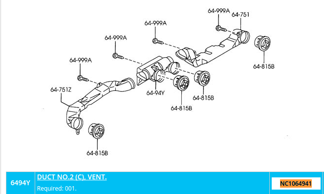
Turns out that Mazda no longer makes the dashboard duct/vent I was hoping to get a replacement for. This is part number NC1064941. Ebay has some but they're a little more than I'd like to pay.
I know some on this forum have parts cars they used to build their Miatas. Here's a pic of what I need, It's the 64-94Y pictured below
Last edited by pj_mcgarvey; 11-07-2016 at 09:56 AM.
 11-01-2016, 08:41 AM
#54
V8 Miata Enthusiast
Thread Starter
Alot of things needed to happen before I could actually proceed with mounting up the engine, but I've had time in the last couple weeks to get through some of it. I need to burn some PTO for work before EOY, so I've had the last two Mondays, and will have the next few Mondays off to dedicate to the project.
I actually want to thank Imgur.com - my new picture hosting site - for providing relief when Photobucket ***** the bed, and also as of this morning making my newly uploaded pictures NOT appear as I type up this post... they were there an hour ago... Hard to find good help these days... You're probably thinking to yourself I have no idea what I'm doing, but no... these sites actually suck for the most part it seems.
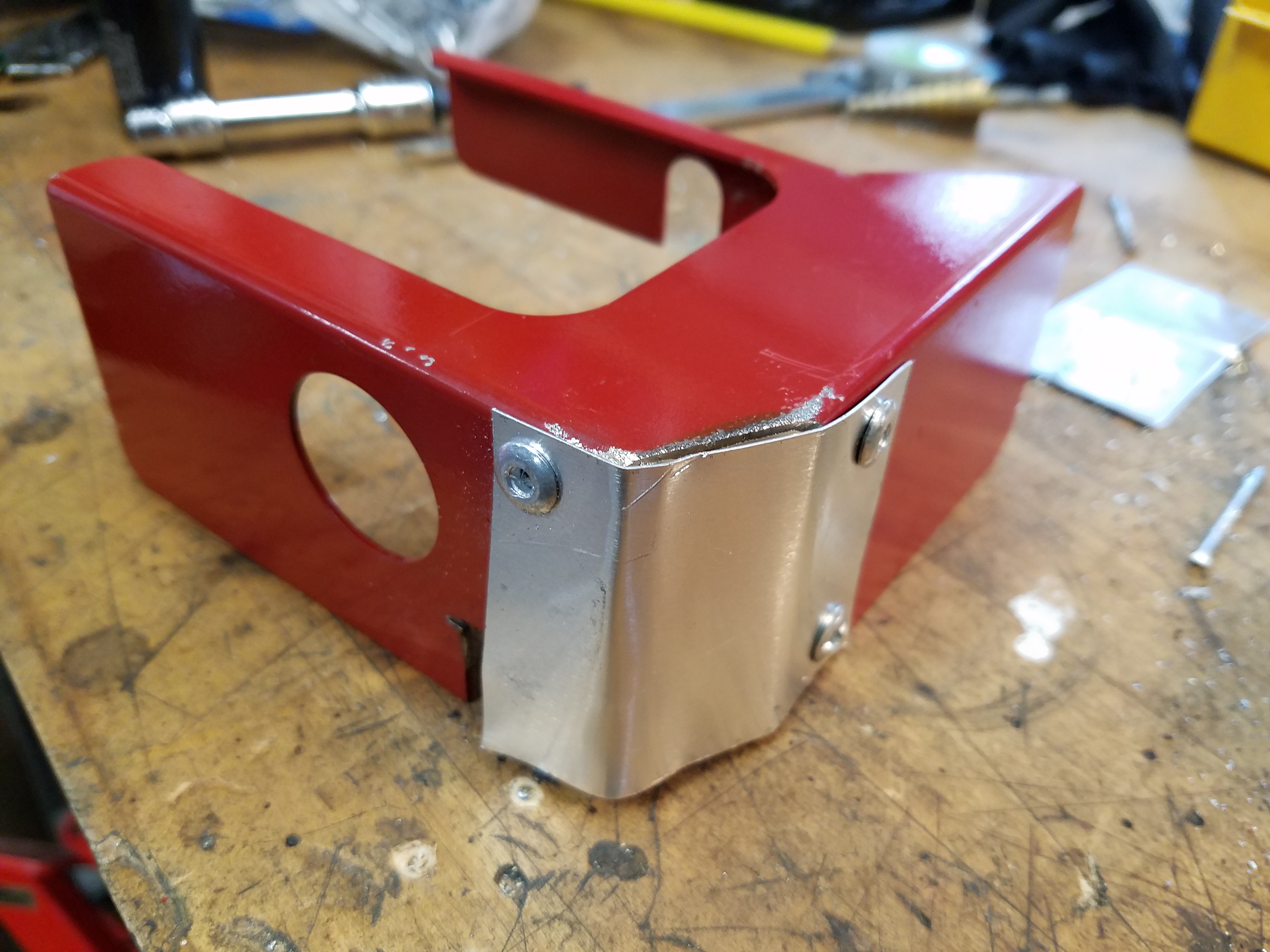
Hit another snag with these motor mounts when I went to mount up the headers. Again for whatever reason, I need to space my mounts away from the block in order to line up with the subframe. The extra 1/2" on each side directly interferes with the header, especially on the passenger side.
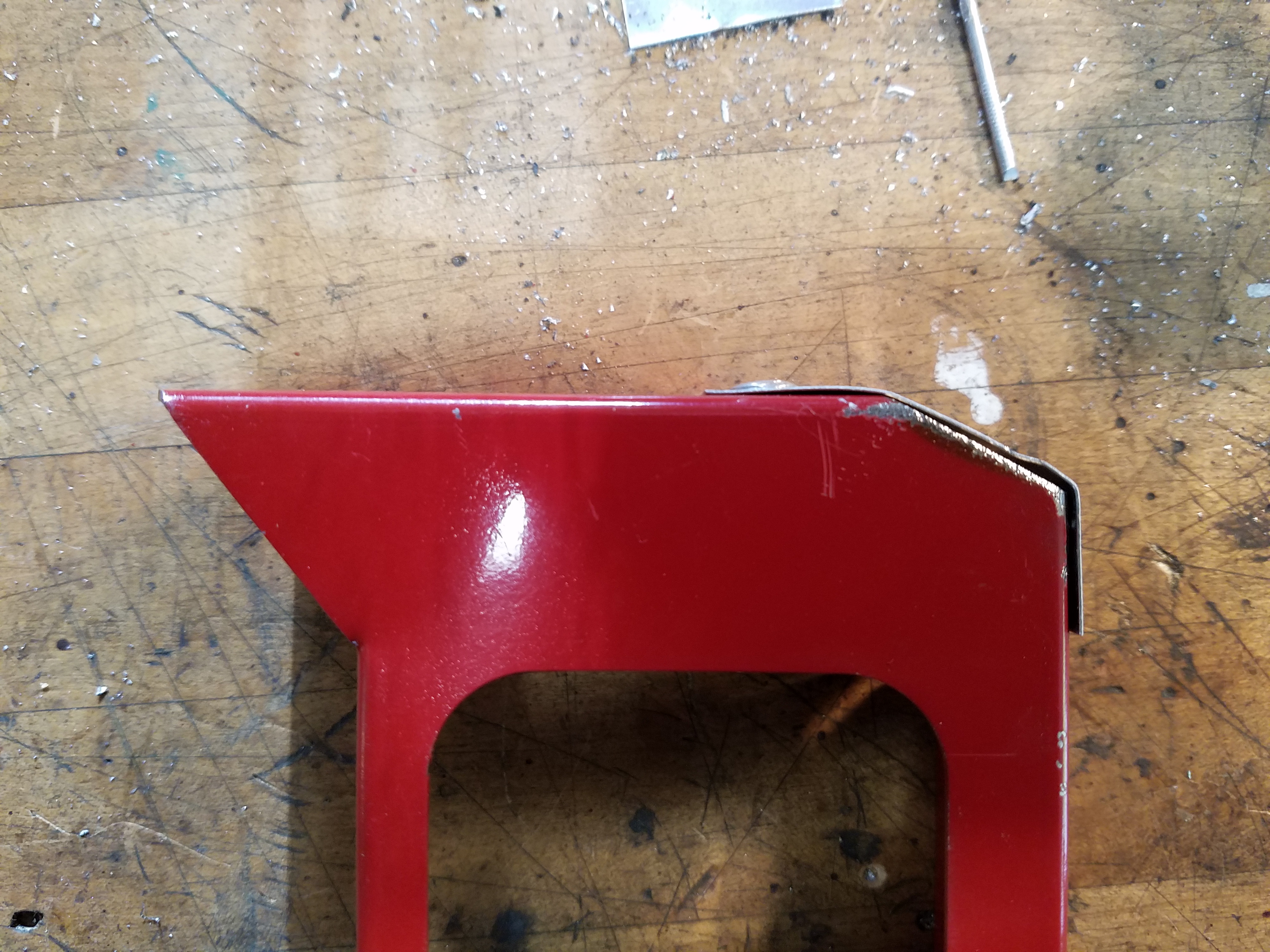
On the driver's side it wasn't too bad, so I cut some of the heat shield away and replaced with some aluminum sheet I riveted to the shield. Clearance is still tight, but I can't make much more without denting the header (no way).
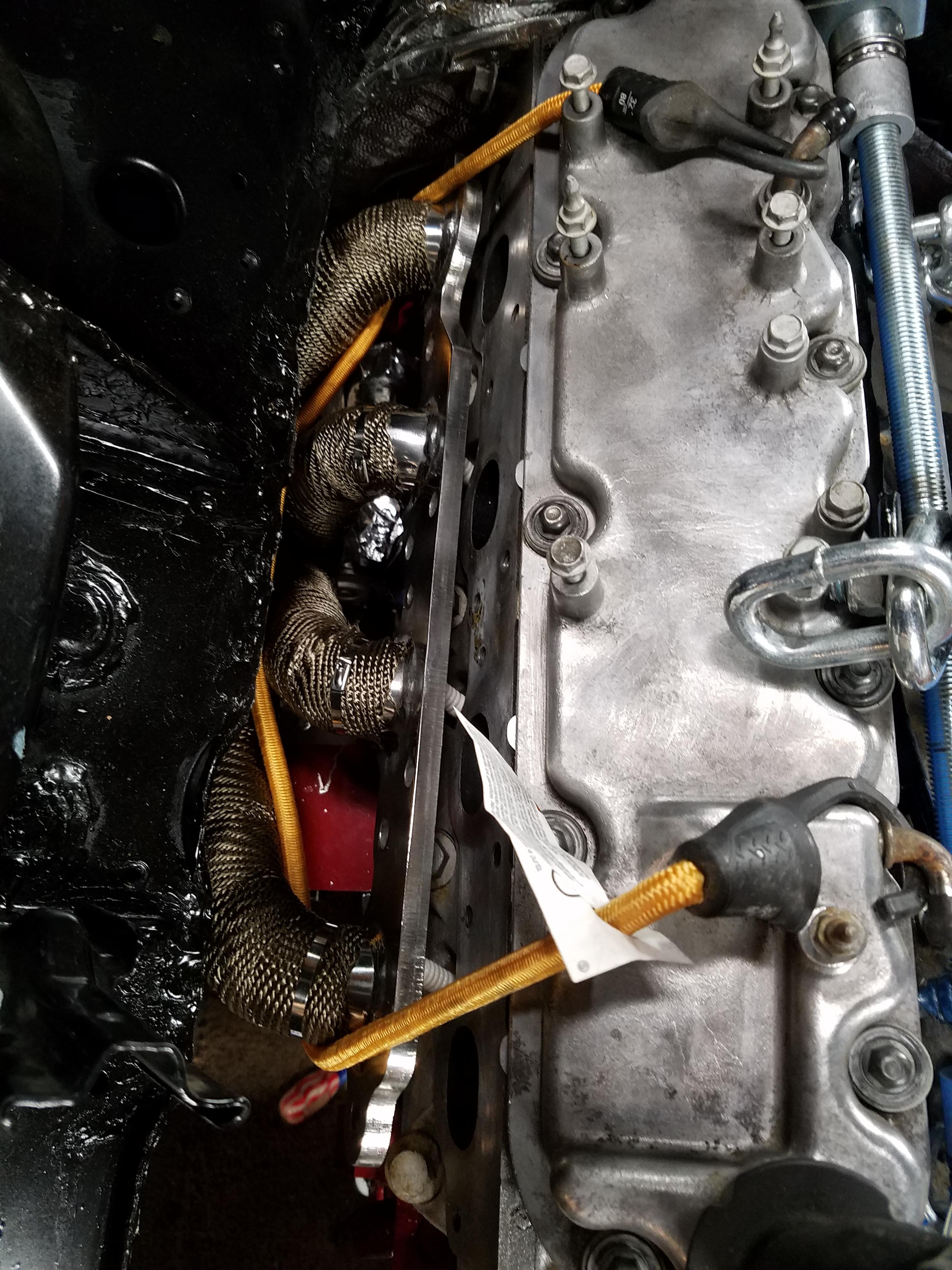
You don't want to see the passenger side mount, it's ugly, but you get the idea. I also applied some of the sticky backed reflective heat shield I used to make my brake line shields, directly to the motor mount itself, on the metal and poly parts. Then I have the motor mount heat shield and then the header wrap. So I think I'm going to be OK on that front. But frustrating nonetheless when you'd rather be bolting up the engine and getting on with it.
Since you install the heat shields after the engine is bolted to the subframe, I had to get creative. I dropped the engine in with headers installed. Then removed the pass. side header and held it place with a bungee so it would fall down and become impossible to get back in place. That gave me room to install the heat shield. The driver's side was tight but not too bad. I left it like this until I knew the engine was staying in place.
Quick link on the header bolts I used: https://www.amazon.com/gp/product/B00CYDLKBE
Installed my Ford 90 degree backup light switch.
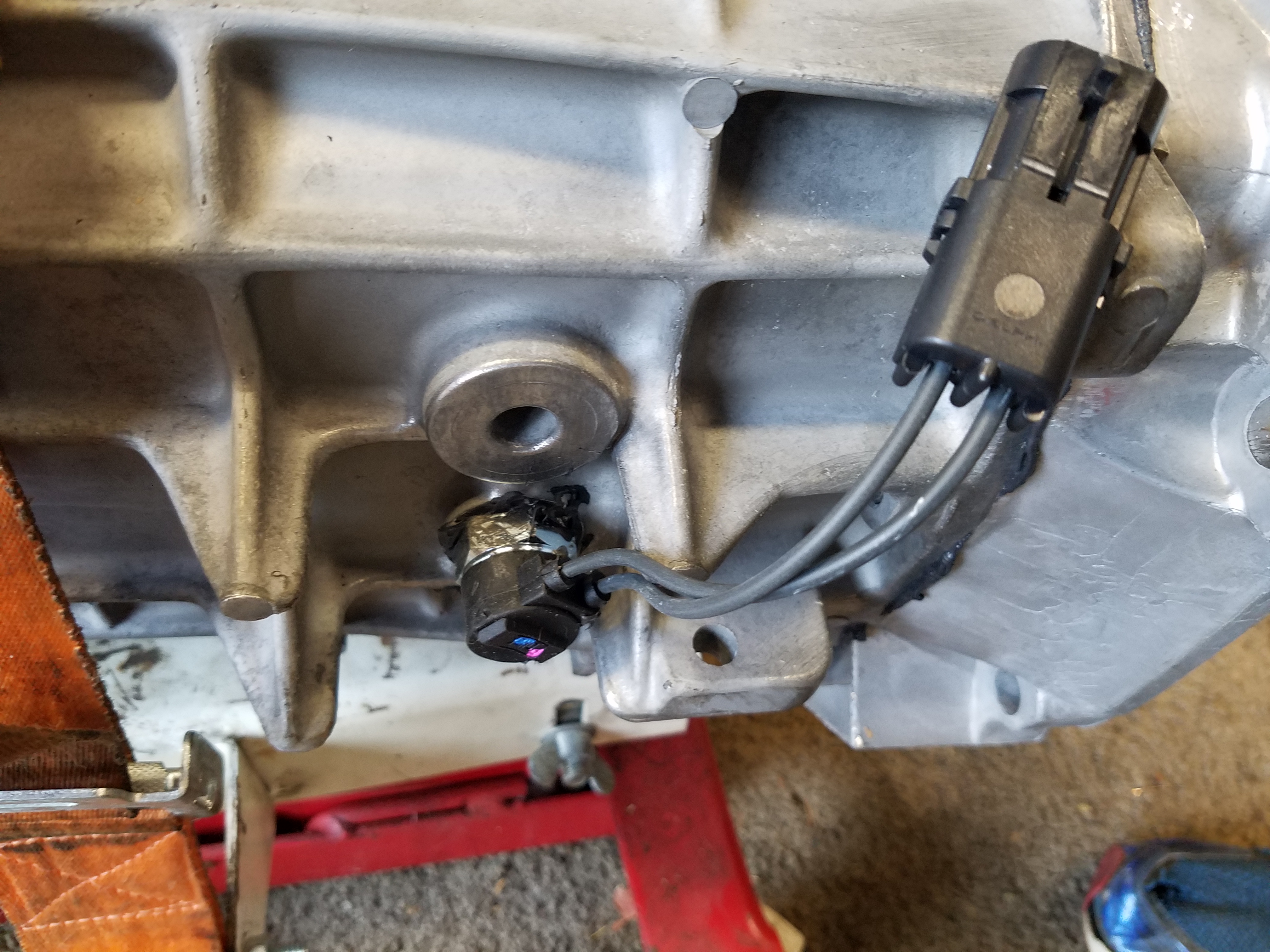
For those not aware this Ford switch has the pigtail at 90 degrees to the mounting hole so you have room in the tunnel to make the connection. Otherwise you may have to dent the tunnel and then worry about any rubbing or movement of the trans damaging the connector. Threads right in.
https://www.amazon.com/gp/product/B000C5DUI2
Mounted up the trans on the transmission jack that has been floating between my garage and my Dad's for a couple decades.
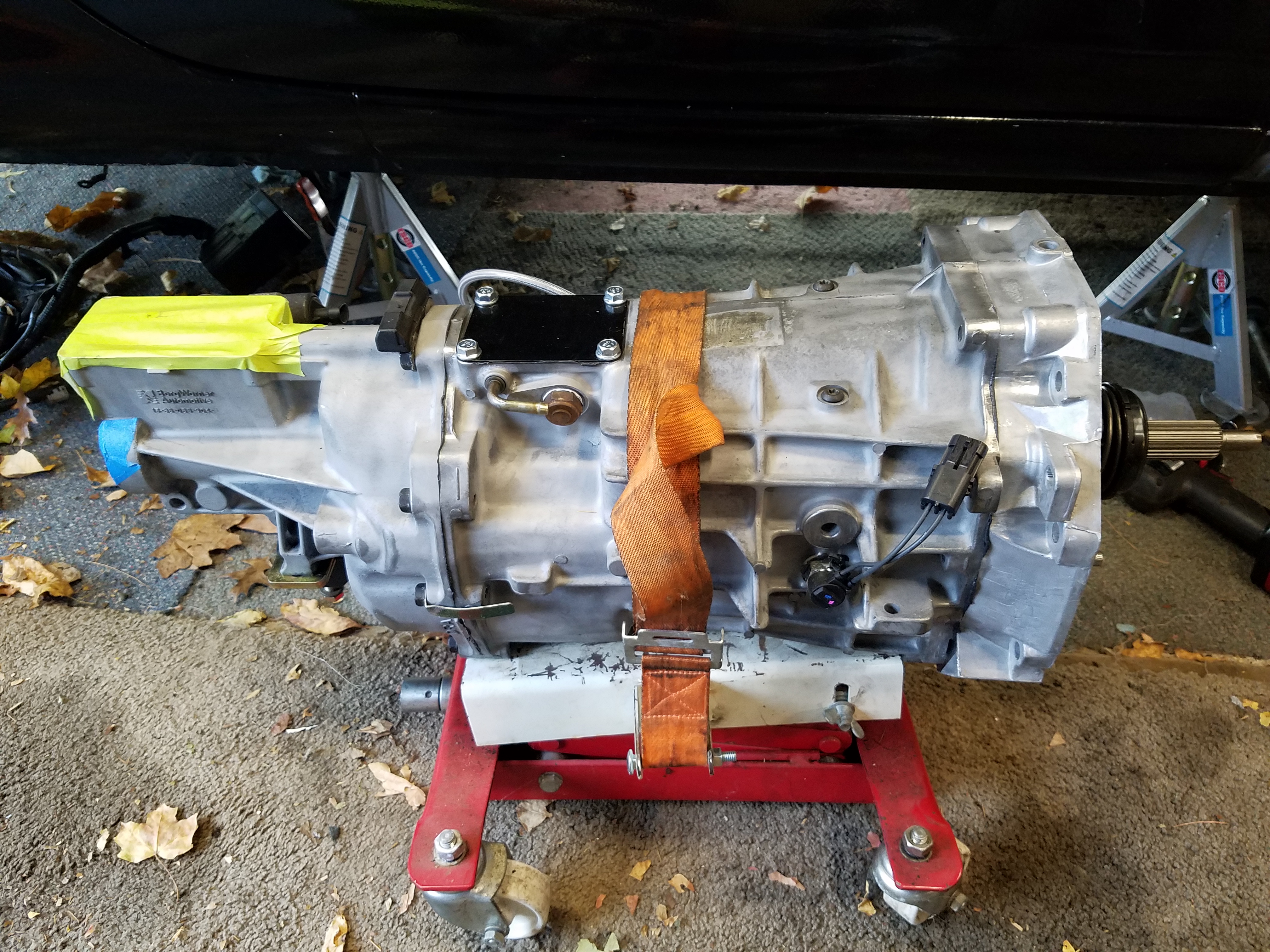
Make sure to install the vent tube on the trans before you mount it up. I had not done this, was afraid might get in the way, get snagged/torn, etc. At some point later when I went to install with the T56 installed, I found it a tight fit to reach up there. Took me a few minutes on my back, but if you have less room or less patience, you will not want to deal with this.
Hydraulic slave cylinder installed.
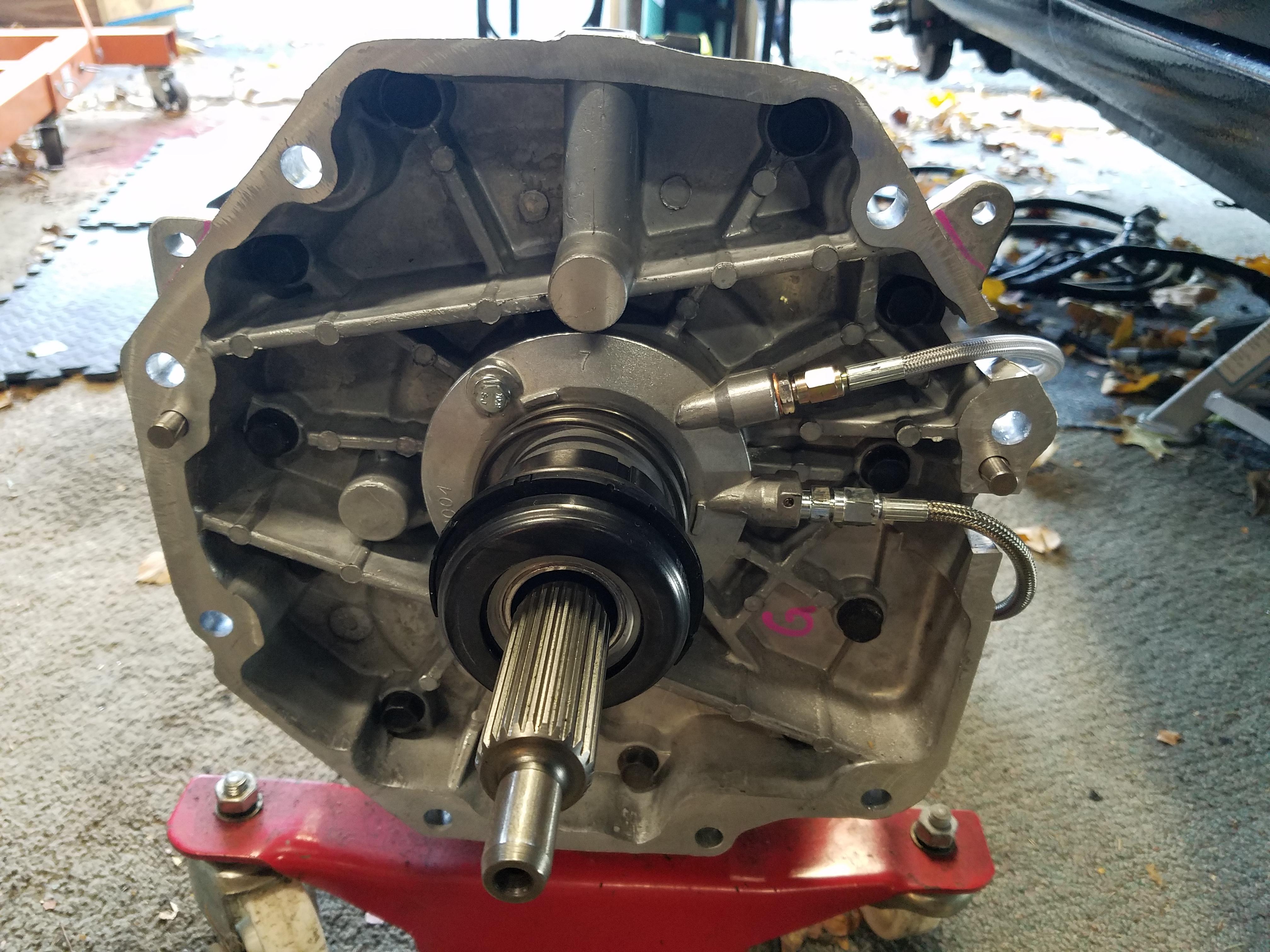
Got my adapter parts from Speedway Motors:
LS1 & LT1 T56 Clutch Line AN3 Banjo Bolt Kit 5151398 $24.99
LS1 & LT1 T56 Release Bearing to AN3 Line Fitting 5151396 $13.99
36 Inch Braided S.S. Brake Line - Straight AN3 91031846-3 $12.99
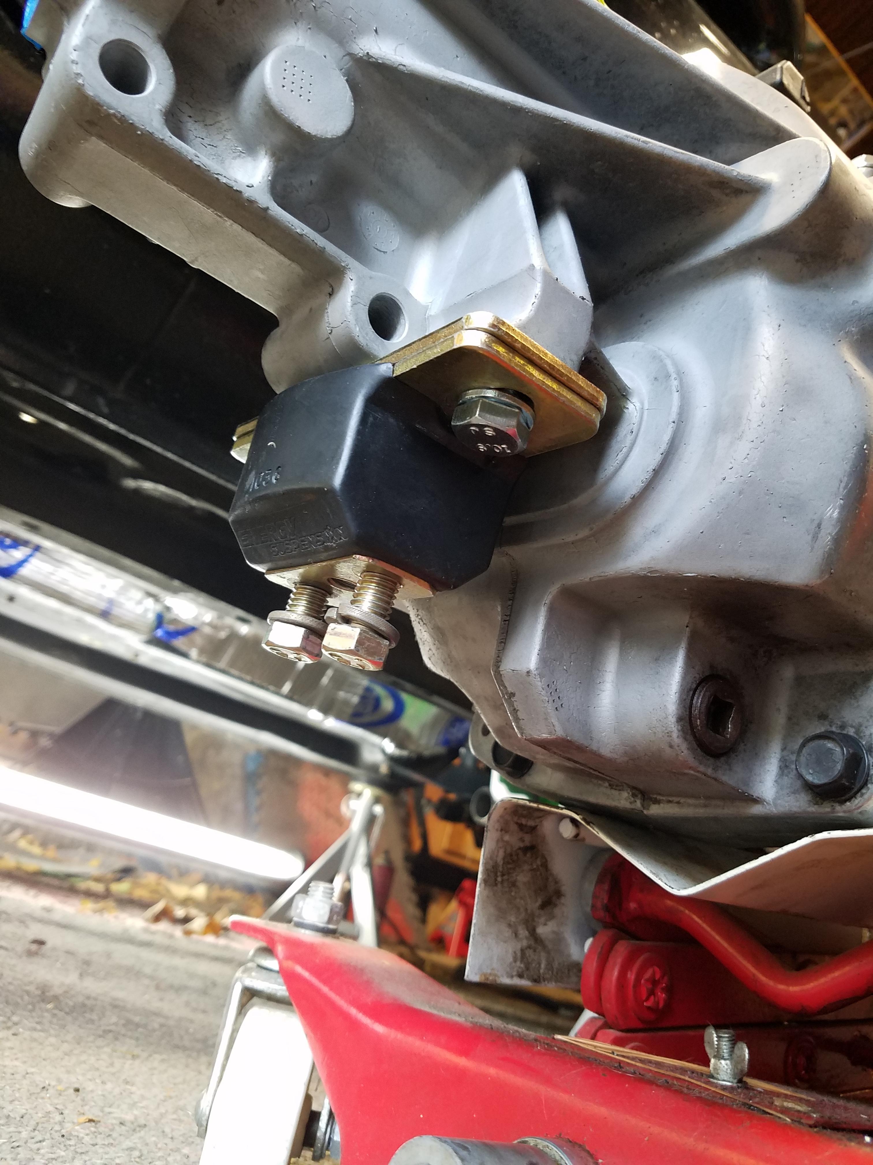
Poly trans mount installed - the rounded part faces the rear - and the "preload" plate is required
I actually want to thank Imgur.com - my new picture hosting site - for providing relief when Photobucket ***** the bed, and also as of this morning making my newly uploaded pictures NOT appear as I type up this post... they were there an hour ago... Hard to find good help these days... You're probably thinking to yourself I have no idea what I'm doing, but no... these sites actually suck for the most part it seems.
Hit another snag with these motor mounts when I went to mount up the headers. Again for whatever reason, I need to space my mounts away from the block in order to line up with the subframe. The extra 1/2" on each side directly interferes with the header, especially on the passenger side.
On the driver's side it wasn't too bad, so I cut some of the heat shield away and replaced with some aluminum sheet I riveted to the shield. Clearance is still tight, but I can't make much more without denting the header (no way).
You don't want to see the passenger side mount, it's ugly, but you get the idea. I also applied some of the sticky backed reflective heat shield I used to make my brake line shields, directly to the motor mount itself, on the metal and poly parts. Then I have the motor mount heat shield and then the header wrap. So I think I'm going to be OK on that front. But frustrating nonetheless when you'd rather be bolting up the engine and getting on with it.
Since you install the heat shields after the engine is bolted to the subframe, I had to get creative. I dropped the engine in with headers installed. Then removed the pass. side header and held it place with a bungee so it would fall down and become impossible to get back in place. That gave me room to install the heat shield. The driver's side was tight but not too bad. I left it like this until I knew the engine was staying in place.
Quick link on the header bolts I used: https://www.amazon.com/gp/product/B00CYDLKBE
Installed my Ford 90 degree backup light switch.
For those not aware this Ford switch has the pigtail at 90 degrees to the mounting hole so you have room in the tunnel to make the connection. Otherwise you may have to dent the tunnel and then worry about any rubbing or movement of the trans damaging the connector. Threads right in.
https://www.amazon.com/gp/product/B000C5DUI2
Mounted up the trans on the transmission jack that has been floating between my garage and my Dad's for a couple decades.
Make sure to install the vent tube on the trans before you mount it up. I had not done this, was afraid might get in the way, get snagged/torn, etc. At some point later when I went to install with the T56 installed, I found it a tight fit to reach up there. Took me a few minutes on my back, but if you have less room or less patience, you will not want to deal with this.
Hydraulic slave cylinder installed.
Got my adapter parts from Speedway Motors:
LS1 & LT1 T56 Clutch Line AN3 Banjo Bolt Kit 5151398 $24.99
LS1 & LT1 T56 Release Bearing to AN3 Line Fitting 5151396 $13.99
36 Inch Braided S.S. Brake Line - Straight AN3 91031846-3 $12.99
Poly trans mount installed - the rounded part faces the rear - and the "preload" plate is required
Last edited by pj_mcgarvey; 12-14-2016 at 08:17 PM.
11-01-2016, 09:41 AM
#55
V8 Miata Enthusiast
Thread Starter
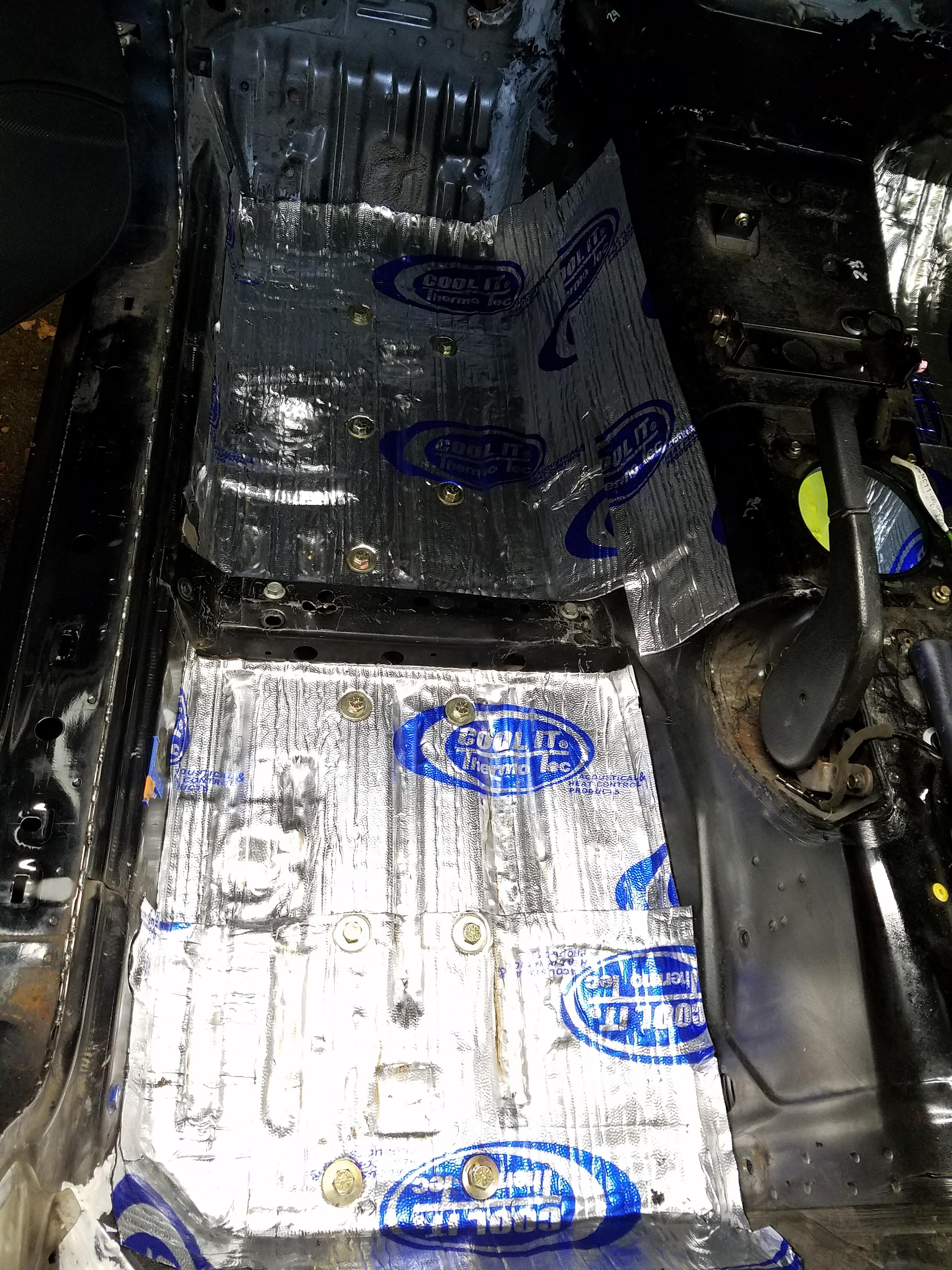
Applied some of the Heat and Sound suppressor to the tunnel area. I had 3 boxes of this, I used a whole box for the tunnel and the firewall where the engine is close to it.
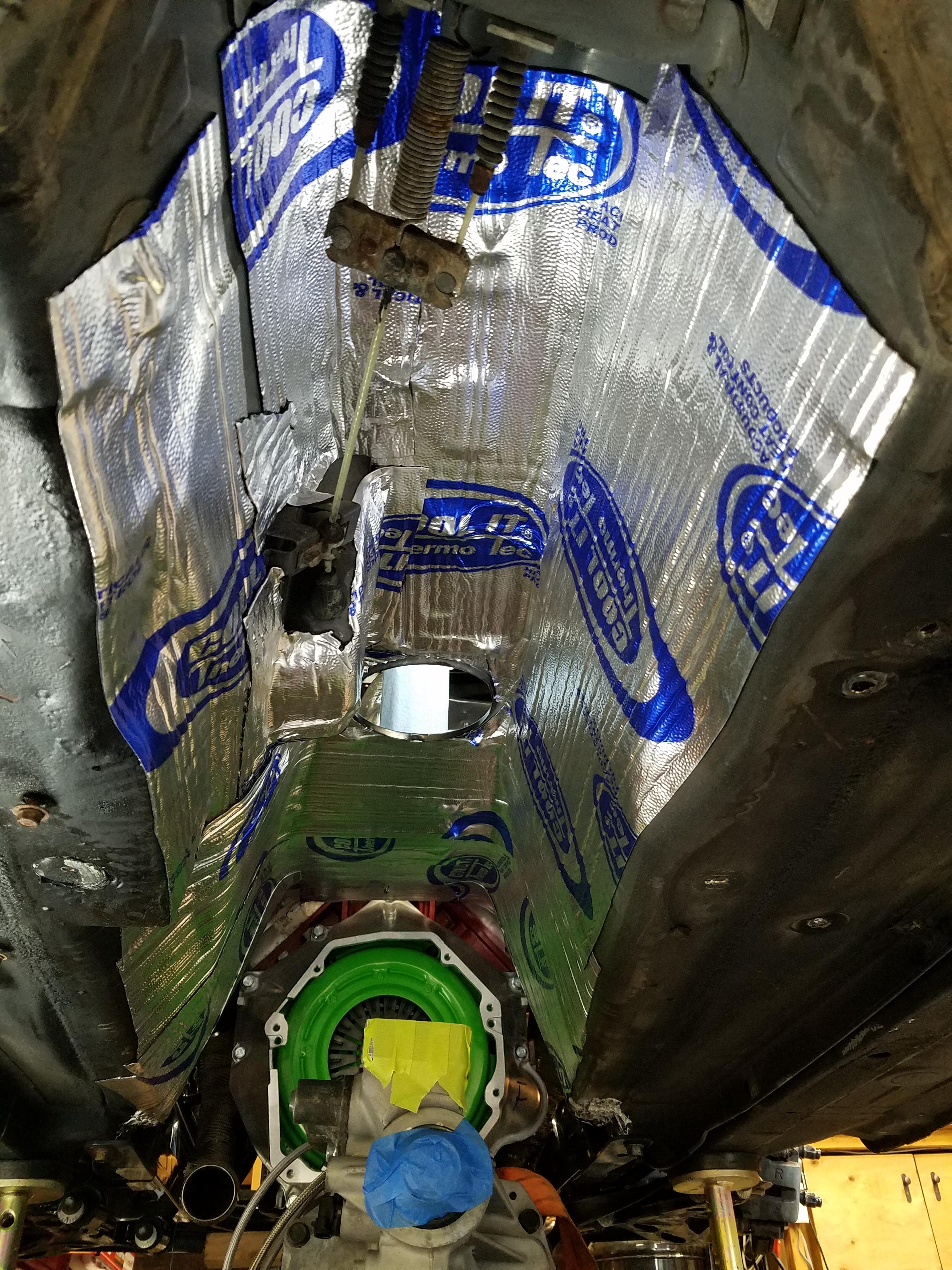
I used my Porter Cable heat gun to get the pieces warm so they could be handled easily. Then I used my J-roller to bed it into the tunnel, with some extra heat from the gun to make it adhere. Temps were in the mid 50s this day, so it needed the help. Used another box of the mat to get some down on the interior floor so I could mount the frame rails through the mat.
So the trans mounting... first I had to raise up the car a few inches so the trans on top of the jack would slide underneath. Since I had no rear subframe installed, this was a bit tricky. I was able to use some 2x4 bracing where the rear subframe normally mounts to lift it up higher. Luckily I was just able to sneak the trans under the car and into place.
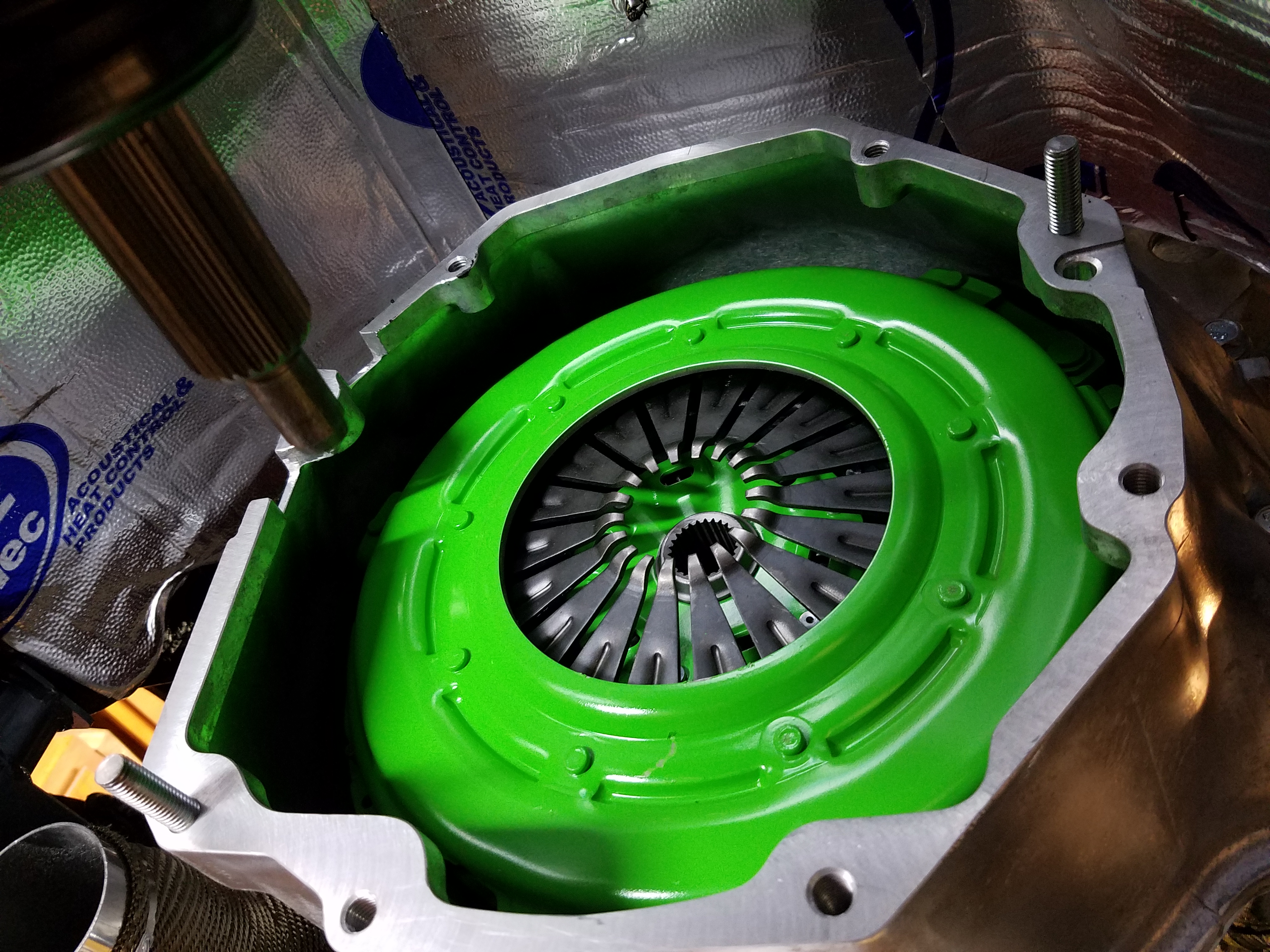
Once I had it in place I took a look at the mounting surface of the bellhousing (attached to the engine) and the trans mounting surface, and tried to get them as parallel as possible by jacking up the engine.
I also had to jack up the trans slowly b/c there is a clearance issue with the emergency brake bumpout on the Miata. So jack it up until the input shaft clears the bottom of the bell, then move it closer to the engine. Then up a bit more until the shaft clears the fingers on the clutch pressure plate, then in some more. Then once the shaft is near the mounting hole start to slide it in. Recheck if the trans and bell are still parallel.
Hello, this is me from the future... if you have issues mounting it up , make sure you check your slave cylinder to pressure plate clearance. The slave cylinder should not be contacting the clutch during the install. If it is, then check my post on addressing this (https://www.v8miata.net/general-moto...ge8/#post23276). Back to the current space in time....
I had some difficulty at first getting it to move into place the final inch or so. My suggestion would be to NOT force it in. Don't hammer at it. I saw similar issues from people on LS1Tech. I thought it was the spring on the slave cylinder at first on mine. I left the trans on the jack overnight and thought this over.
The next day I picked up some longer bolts in a 10mm x 1.5 and cut the heads off to make them into studs. I threaded the studs into the bell housing and installed the trans again getting the studs lined up into the mounting holes.You can see them threaded into the bell.
So far so good. Initially things were not mating up as closely as before. This time I tried to lower the engine a hair and magically with one push it clunked right in. I only had about 1/4" where I couldn't get it to fully slide in but I knew I was close.
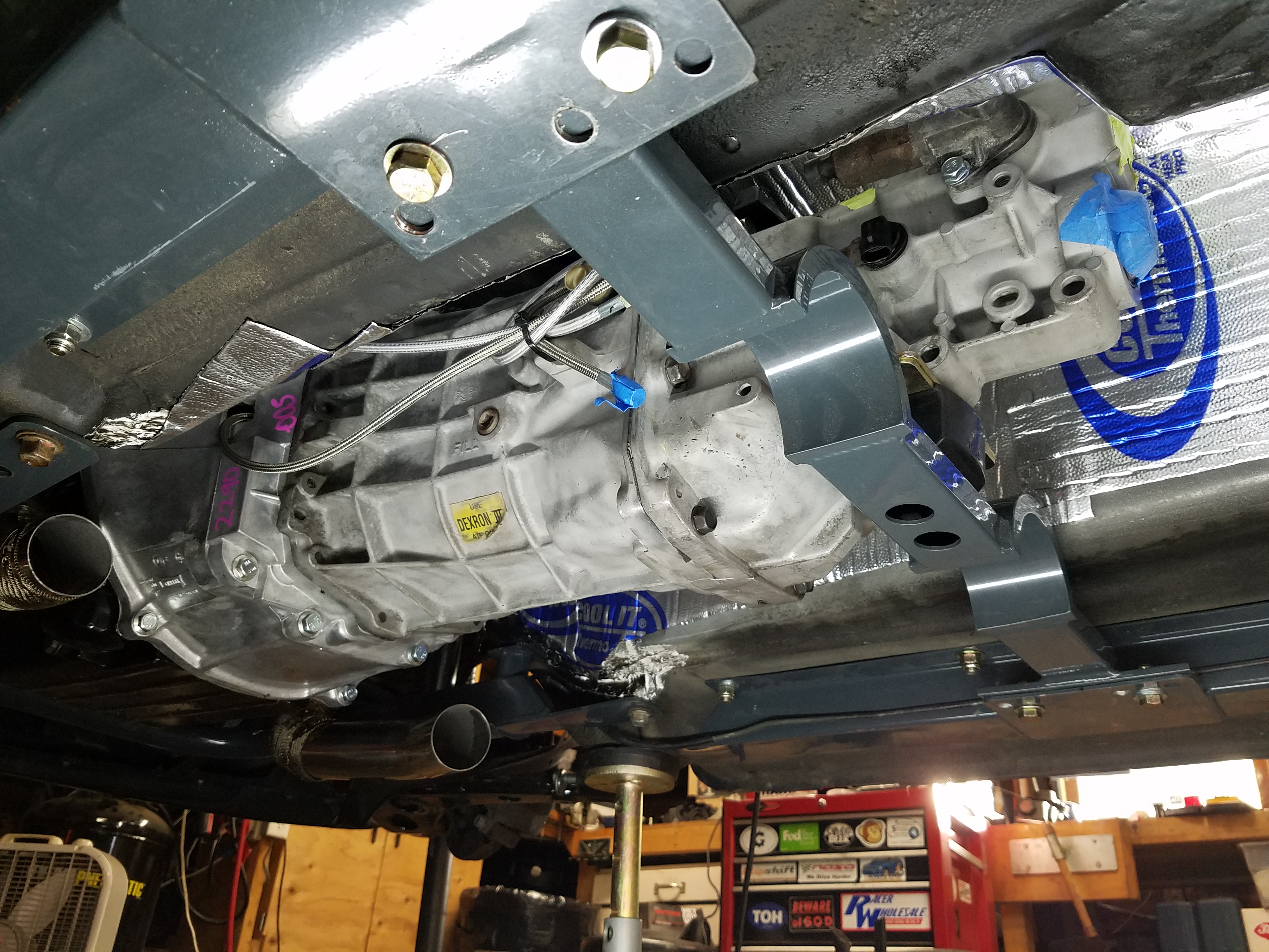
I used a bolt on the studs to pull it tight slowly, then threaded in the other install bolts to slowly tighten things up. Final torque at 37 ft. lbs. and I was good to go.
Finished the day by installing the trans cross member and then the frame rails so they lined up with the cross member. This part of the job flew by so that by end of a productive day I had a full installed trans and I could take a break from working on my back under the car.
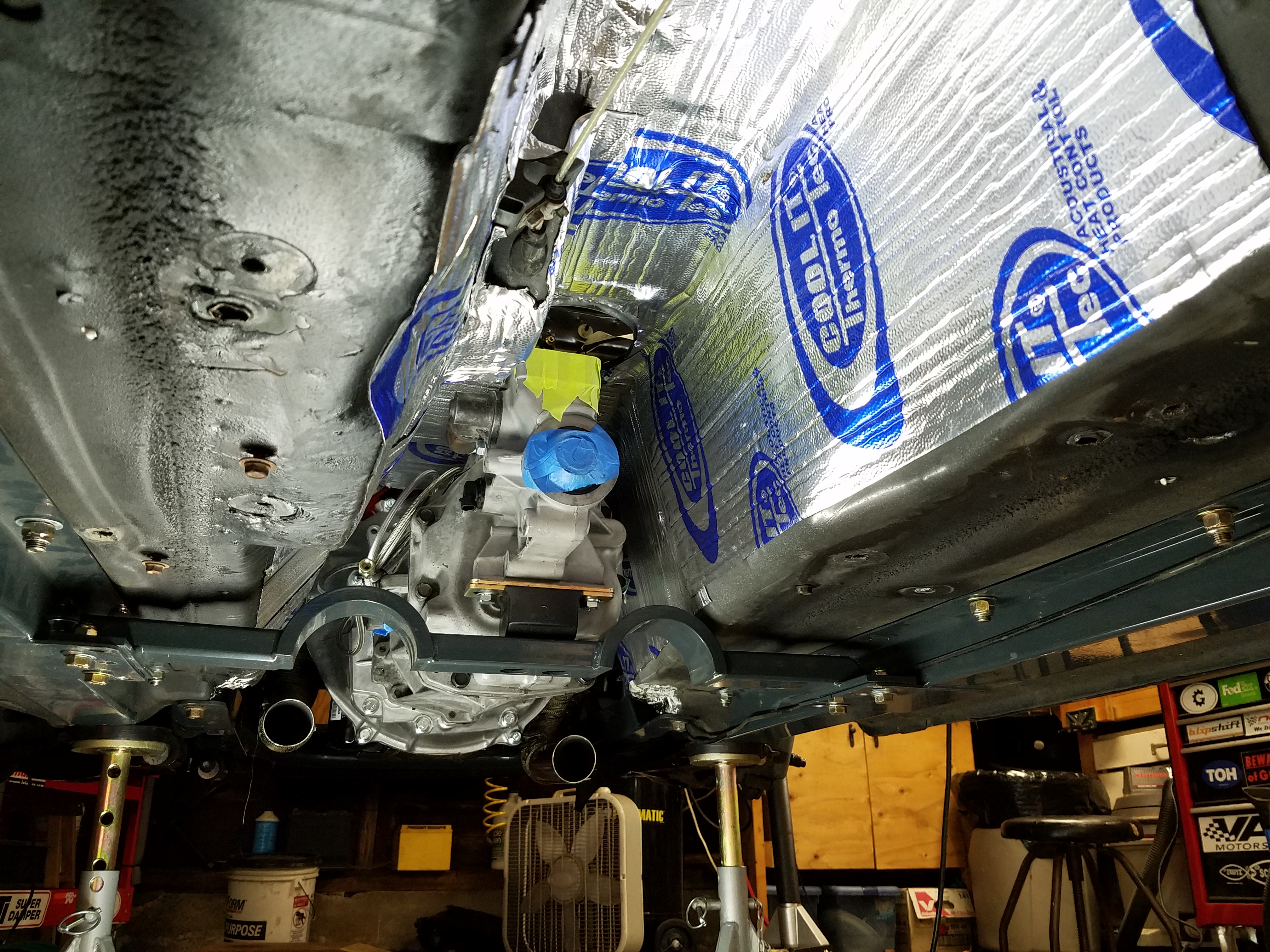
Pic of the interior sound/heat mat installed and frame rail bolts
Going to work on the clutch master install next, bolt up the loose header, and test fit the radiator with the Flyin Miata Stage 2 fan shroud and fans.
I'm loving the extra space on the garage floor now so may start to fab up the rear diff setup as well.
Also might have a buyer for the Miata engine/trans... let's hope!
I used my Porter Cable heat gun to get the pieces warm so they could be handled easily. Then I used my J-roller to bed it into the tunnel, with some extra heat from the gun to make it adhere. Temps were in the mid 50s this day, so it needed the help. Used another box of the mat to get some down on the interior floor so I could mount the frame rails through the mat.
So the trans mounting... first I had to raise up the car a few inches so the trans on top of the jack would slide underneath. Since I had no rear subframe installed, this was a bit tricky. I was able to use some 2x4 bracing where the rear subframe normally mounts to lift it up higher. Luckily I was just able to sneak the trans under the car and into place.
Once I had it in place I took a look at the mounting surface of the bellhousing (attached to the engine) and the trans mounting surface, and tried to get them as parallel as possible by jacking up the engine.
I also had to jack up the trans slowly b/c there is a clearance issue with the emergency brake bumpout on the Miata. So jack it up until the input shaft clears the bottom of the bell, then move it closer to the engine. Then up a bit more until the shaft clears the fingers on the clutch pressure plate, then in some more. Then once the shaft is near the mounting hole start to slide it in. Recheck if the trans and bell are still parallel.
Hello, this is me from the future... if you have issues mounting it up , make sure you check your slave cylinder to pressure plate clearance. The slave cylinder should not be contacting the clutch during the install. If it is, then check my post on addressing this (https://www.v8miata.net/general-moto...ge8/#post23276). Back to the current space in time....
I had some difficulty at first getting it to move into place the final inch or so. My suggestion would be to NOT force it in. Don't hammer at it. I saw similar issues from people on LS1Tech. I thought it was the spring on the slave cylinder at first on mine. I left the trans on the jack overnight and thought this over.
The next day I picked up some longer bolts in a 10mm x 1.5 and cut the heads off to make them into studs. I threaded the studs into the bell housing and installed the trans again getting the studs lined up into the mounting holes.You can see them threaded into the bell.
So far so good. Initially things were not mating up as closely as before. This time I tried to lower the engine a hair and magically with one push it clunked right in. I only had about 1/4" where I couldn't get it to fully slide in but I knew I was close.
I used a bolt on the studs to pull it tight slowly, then threaded in the other install bolts to slowly tighten things up. Final torque at 37 ft. lbs. and I was good to go.
Finished the day by installing the trans cross member and then the frame rails so they lined up with the cross member. This part of the job flew by so that by end of a productive day I had a full installed trans and I could take a break from working on my back under the car.
Pic of the interior sound/heat mat installed and frame rail bolts
Going to work on the clutch master install next, bolt up the loose header, and test fit the radiator with the Flyin Miata Stage 2 fan shroud and fans.
I'm loving the extra space on the garage floor now so may start to fab up the rear diff setup as well.
Also might have a buyer for the Miata engine/trans... let's hope!
Last edited by pj_mcgarvey; 07-31-2017 at 09:22 AM.
11-08-2016, 03:19 PM
#56
V8 Miata Enthusiast
Thread Starter
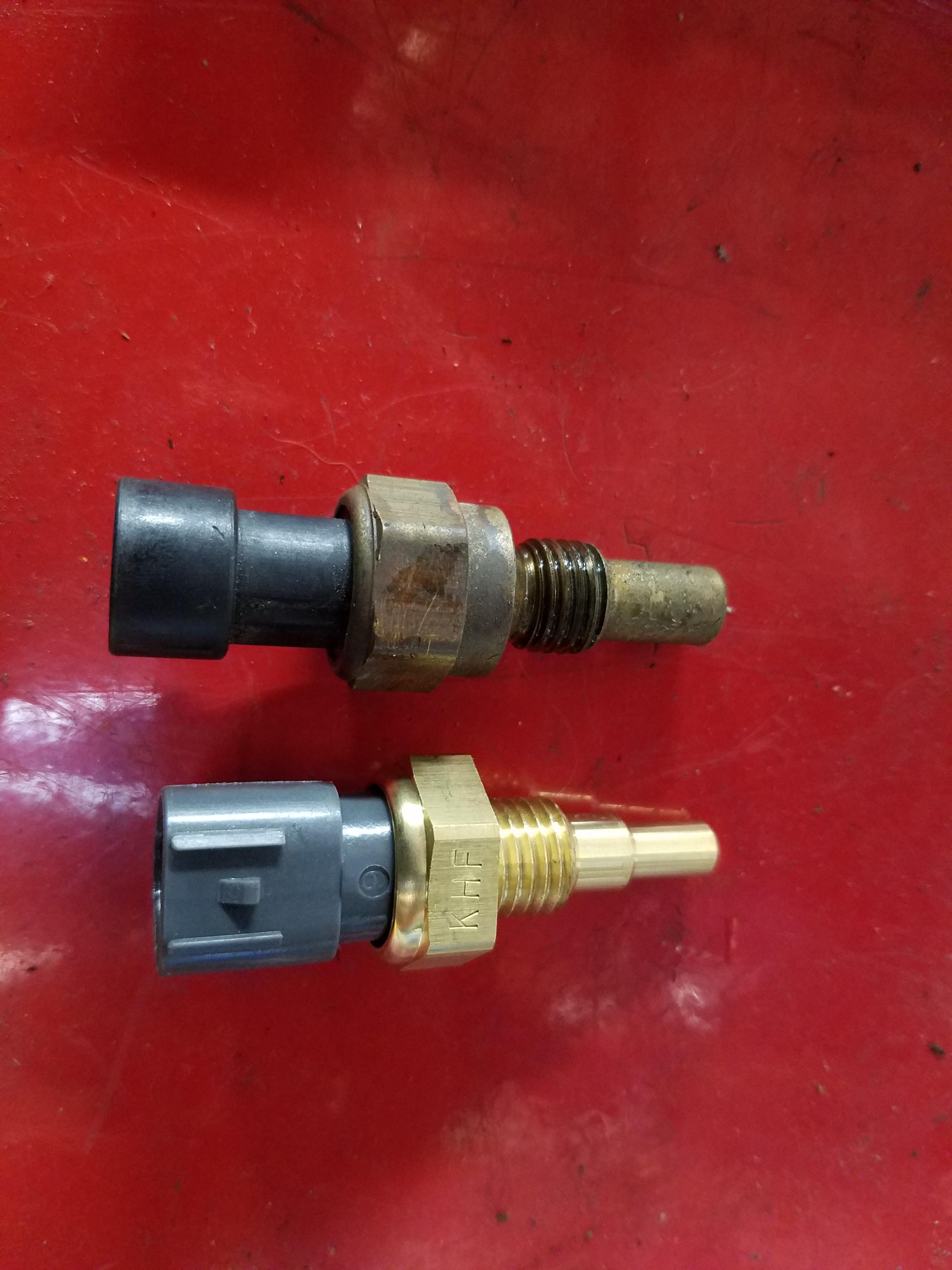
Installed a new Miata coolant sensor which conveniently threads right into the same port as the LS1 sensor. Here are the two side by side. I've been told (thanks wcw5023) you will still need to run the LS1 sensor for the PCM to be happy, but the Miata sensor will feed your dash gauge for the correct temp. There is another water temp port at the back of the passenger side head.
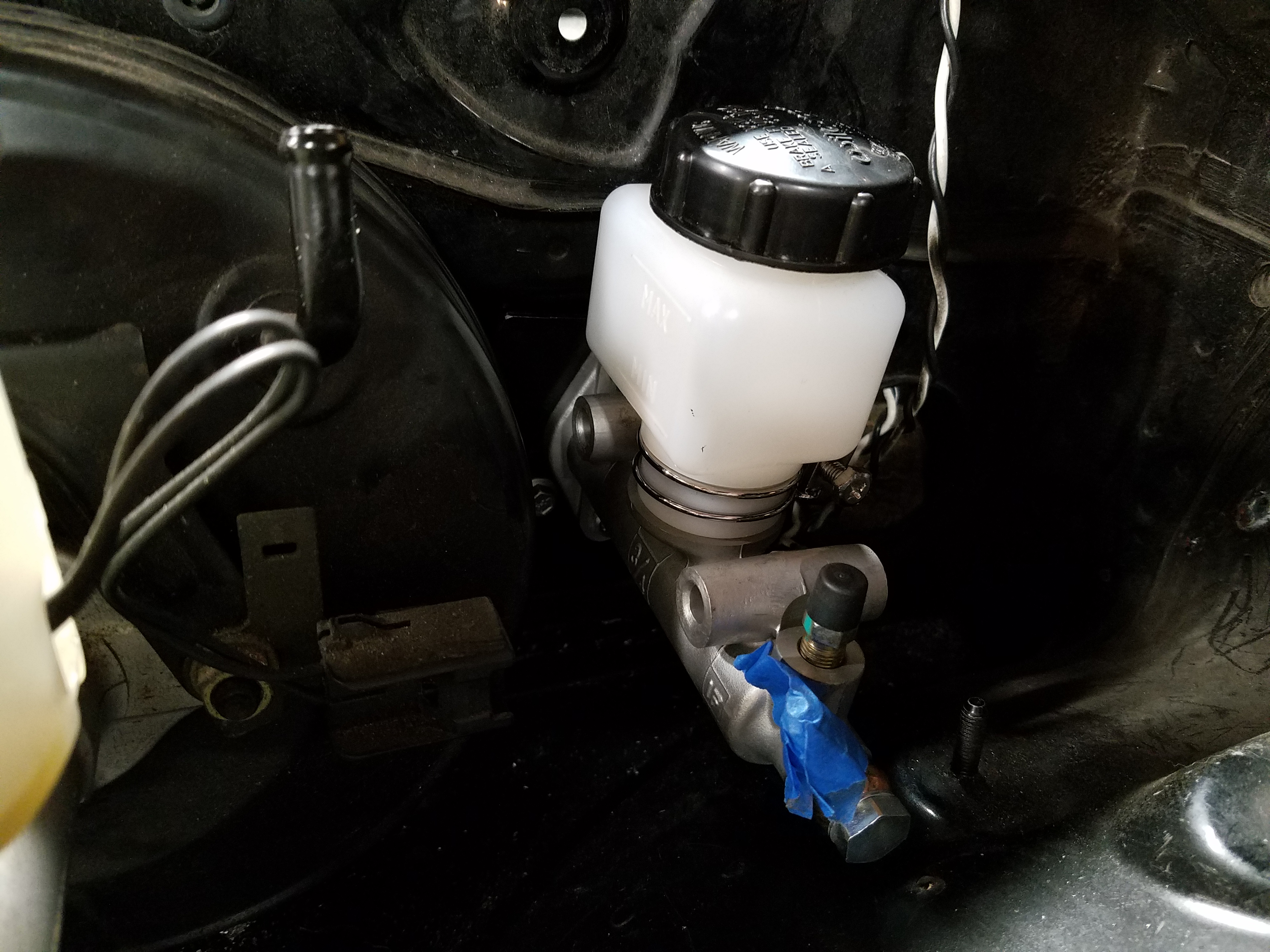
Clutch master cylinder adapter plate fitted up and held in place so I can mark the holes for the MC itself and the bolt holes.
Marked from the back.
Final install
Worked on getting the new rear hubs and wheel bearings installed. I bought the driveshafts and hubs from Driveshaft Shop, though actually through an online vendor that was about $100 less than DSS themselves, or other vendors I found. Woot.
DriveShaft MZFD25 600HP Axle/Hub Kit 89-05 Mazda Miata W/8.8 Rear Conversion
Yeah, that price stung a bit, but they are the 600hp version, so should be a set it and forget it affair. Hubs and lug bolts included.
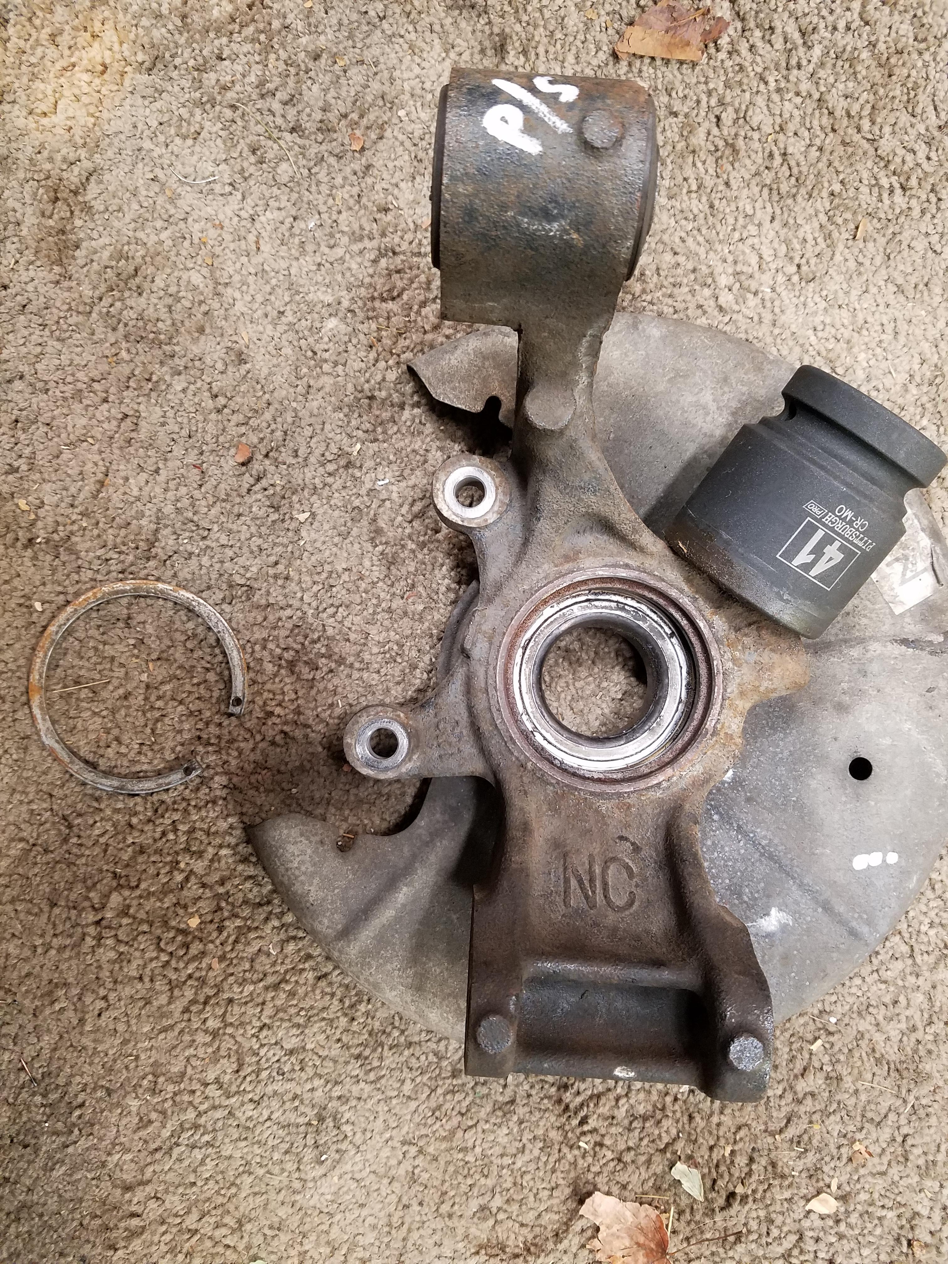
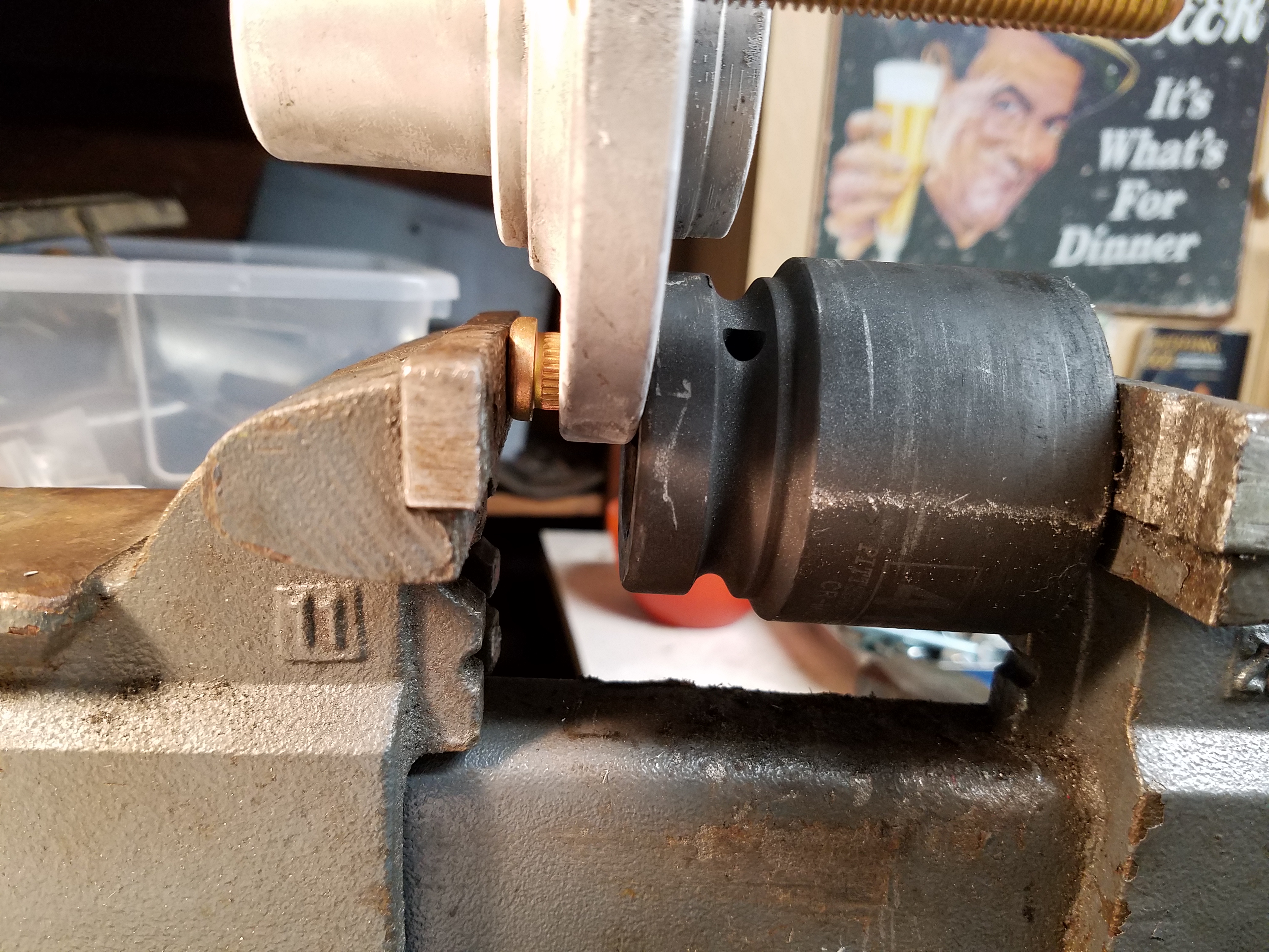
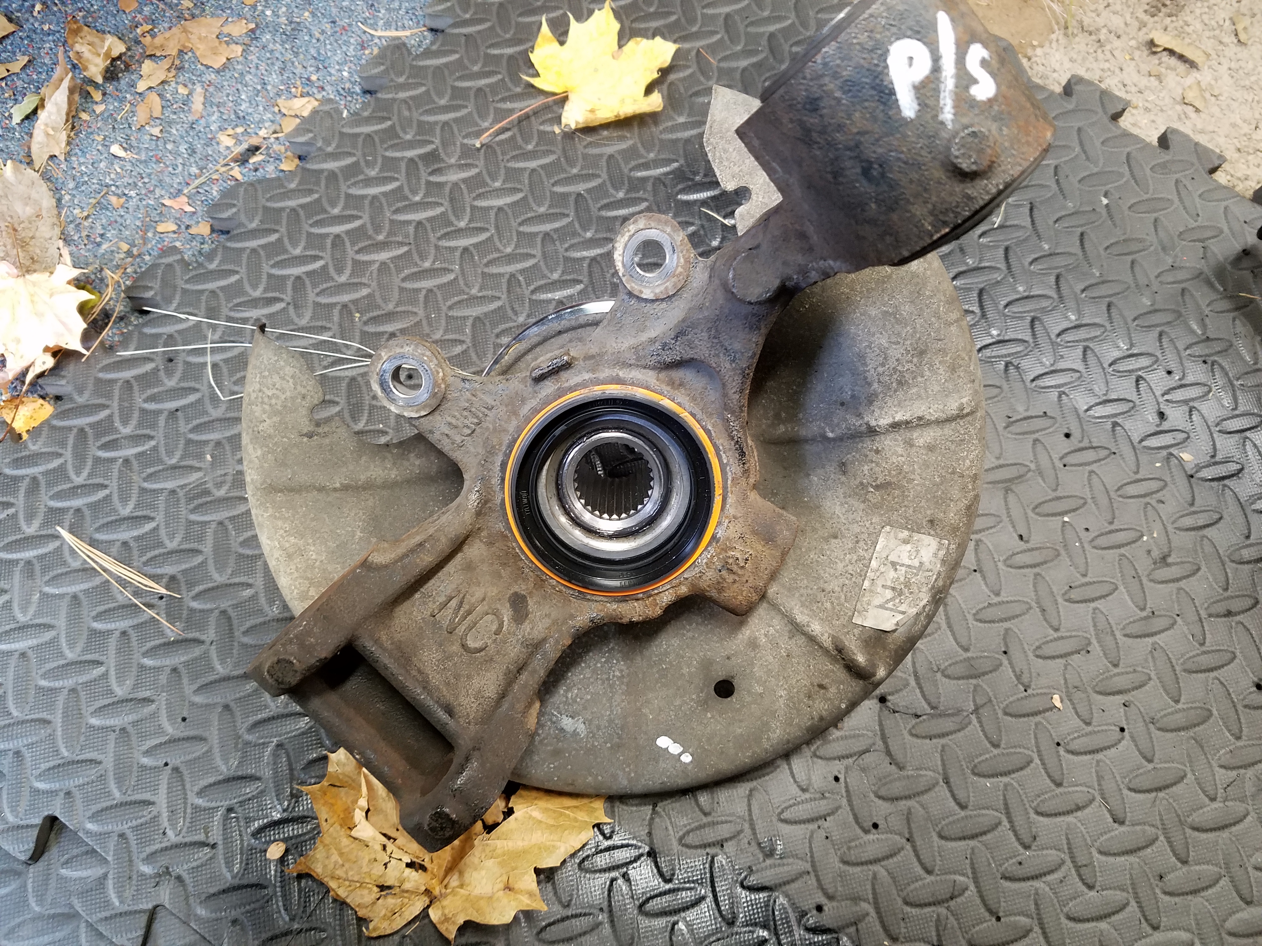
This is how I broke the spindles down. First tried with a slide hammer, but after awhile I realized that was going to be pointless. I'm not reusing these, so don't care how hard I beat on them. So the pic shows my drilling hammer hitting an appropriately sized impact socket. I hold the socket with a vise grip against the hub and wail away at it until it pops out.
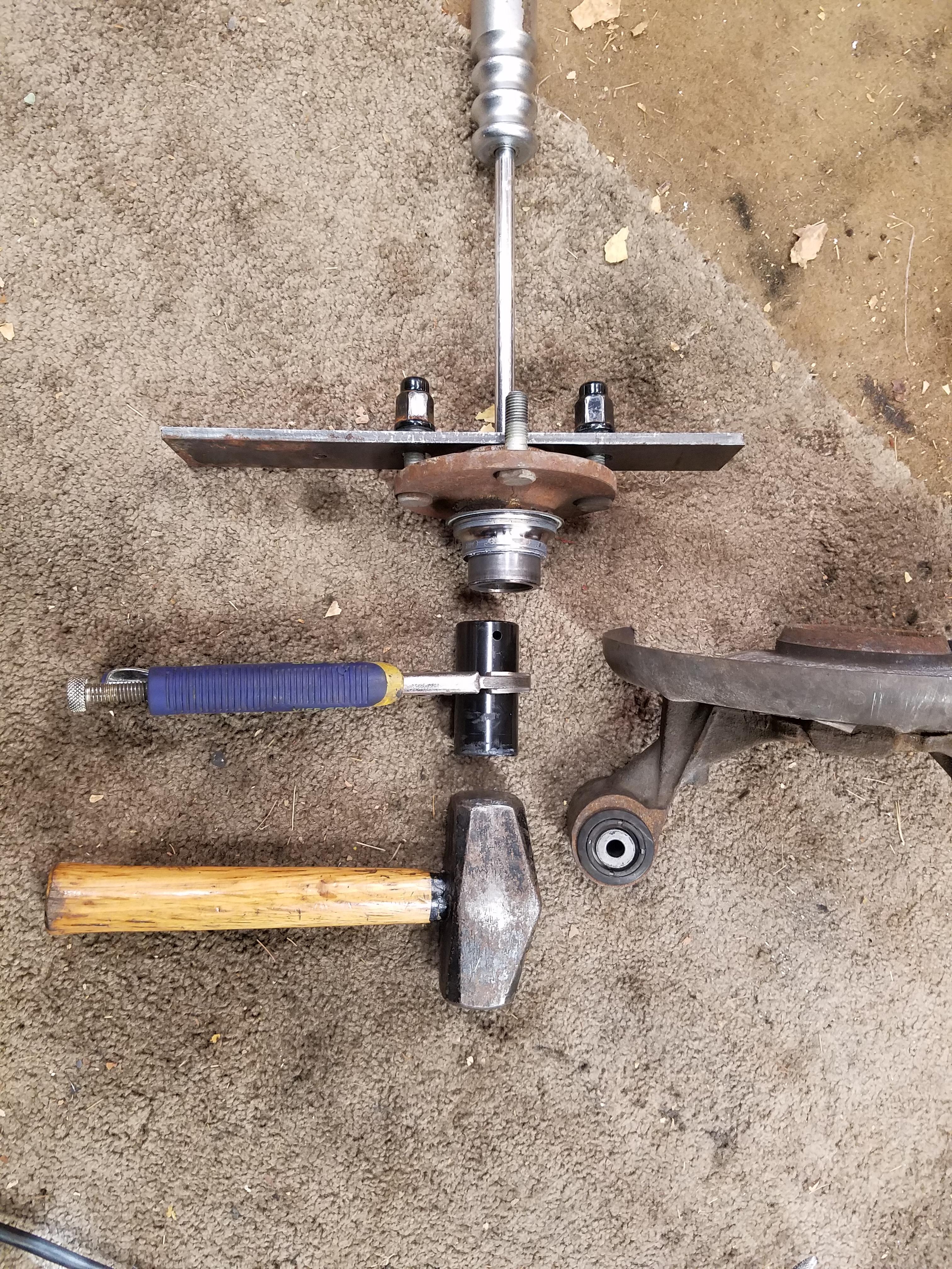
Next you need to remove the large circlip or that bearing isn't going anywhere. Right angle needle nose pliers worked fine for me. Then use another appropriately sized socket to pound out the bearing by trying to make contact with the outer race of the bearing. This socket is huge and came in a reasonably priced kit from Harbor Freight. They have 1" drive sizes which I don't even have a wrench for, but they are great for stuff like this.
You may find it helpful to use your vice and gravity
Once they're out, clean up the bore on the spindle and check for any damage. Save the old bearings b/c you can use them as install tools in the next step.
Clutch master cylinder adapter plate fitted up and held in place so I can mark the holes for the MC itself and the bolt holes.
Marked from the back.
Final install
Worked on getting the new rear hubs and wheel bearings installed. I bought the driveshafts and hubs from Driveshaft Shop, though actually through an online vendor that was about $100 less than DSS themselves, or other vendors I found. Woot.
DriveShaft MZFD25 600HP Axle/Hub Kit 89-05 Mazda Miata W/8.8 Rear Conversion
Yeah, that price stung a bit, but they are the 600hp version, so should be a set it and forget it affair. Hubs and lug bolts included.
This is how I broke the spindles down. First tried with a slide hammer, but after awhile I realized that was going to be pointless. I'm not reusing these, so don't care how hard I beat on them. So the pic shows my drilling hammer hitting an appropriately sized impact socket. I hold the socket with a vise grip against the hub and wail away at it until it pops out.
Next you need to remove the large circlip or that bearing isn't going anywhere. Right angle needle nose pliers worked fine for me. Then use another appropriately sized socket to pound out the bearing by trying to make contact with the outer race of the bearing. This socket is huge and came in a reasonably priced kit from Harbor Freight. They have 1" drive sizes which I don't even have a wrench for, but they are great for stuff like this.
You may find it helpful to use your vice and gravity
Once they're out, clean up the bore on the spindle and check for any damage. Save the old bearings b/c you can use them as install tools in the next step.
Last edited by pj_mcgarvey; 11-08-2016 at 04:35 PM.
11-08-2016, 03:24 PM
#57
V8 Miata Follower

Nice progress! Feels good to get a handful of these little projects out of the way doesnt it?
Did you remove the LS1 coolant sensor entirely? The PCM will still need to read from it, so typically most put the miata sensor into the plugged off port on the rear of the passenger side head.
Did you remove the LS1 coolant sensor entirely? The PCM will still need to read from it, so typically most put the miata sensor into the plugged off port on the rear of the passenger side head.
11-08-2016, 03:40 PM
#58
V8 Miata Enthusiast
Thread Starter
Before you start with the new hubs and bearings, it may help to freeze them overnight to shrink them a bit and help with fitting large pieces of metal into slightly larger holes.
Bury the hubs and bearings underneath the steak and chicken so your vegetarian wife will never notice.
I used a socket long enough to "catch" the lub bolt and pressed in like so
That is until your vice surrenders with a dull sounding crack
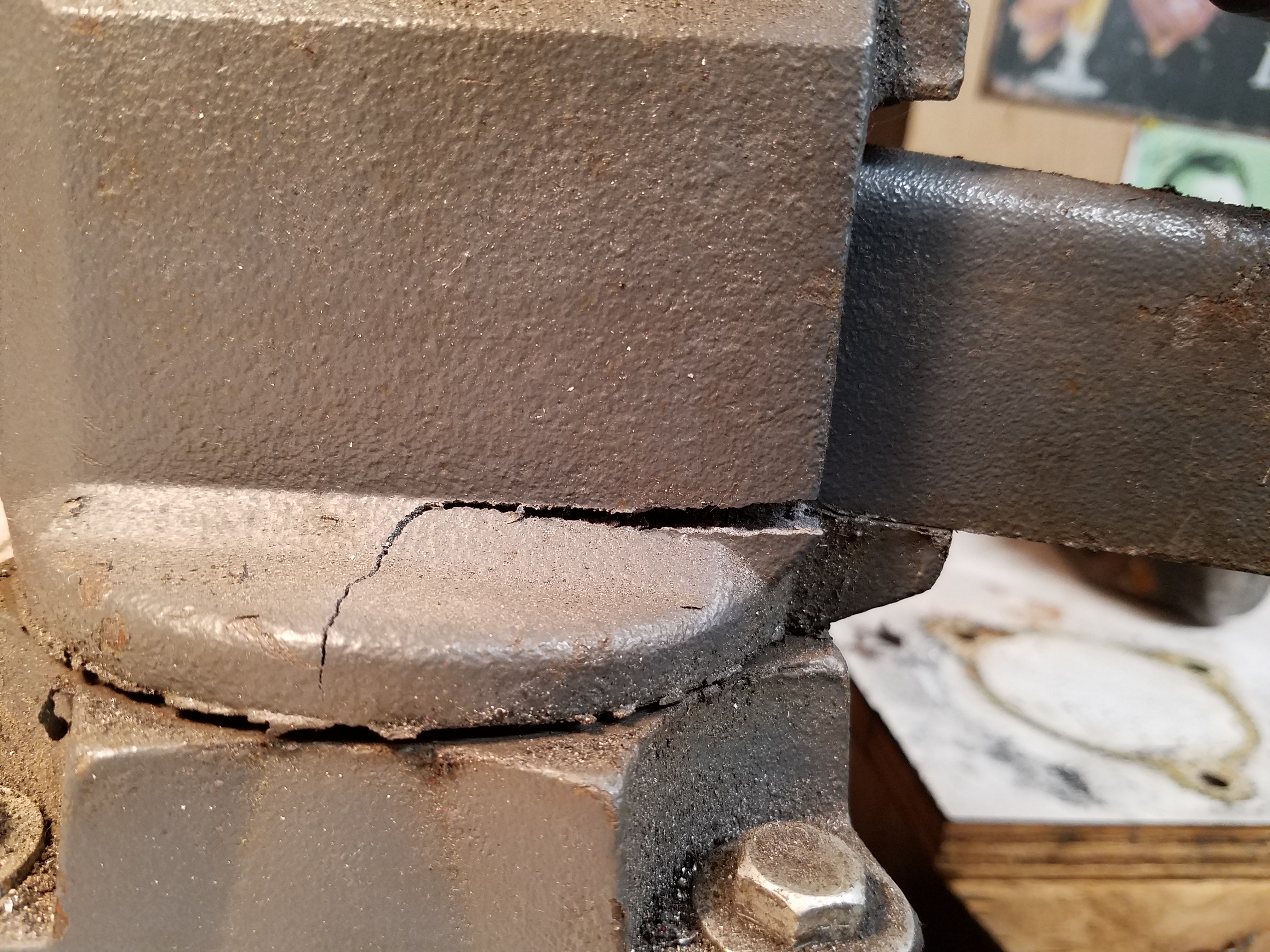
No big deal, that's what a BFH is for. Just make sure you seat the lug bolt head all the way and make sure the threaded part is 90 degrees to the hub face when done and you should be good. This was the easy part.
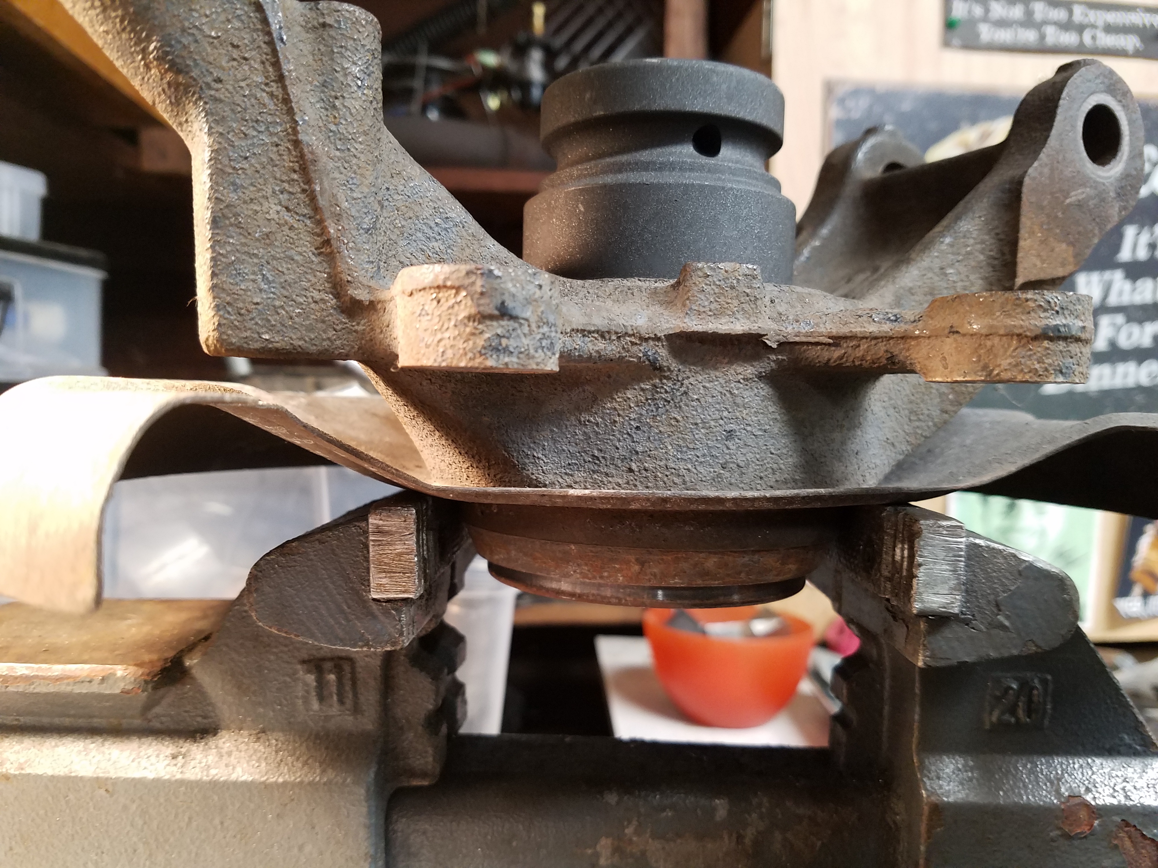
Use the old bearing (on top) to tap the new bearing into the spindle. I put some light moly grease on the spindle bore. I suppose you could also heat up the spindle with a torch or oven, that might really make it easy. I used a hose clamp to keep them perfectly aligned. If you don't you could nick the new bearing race making it harder to slide into place, or worse damage the rubber seal. Don't **** this up.
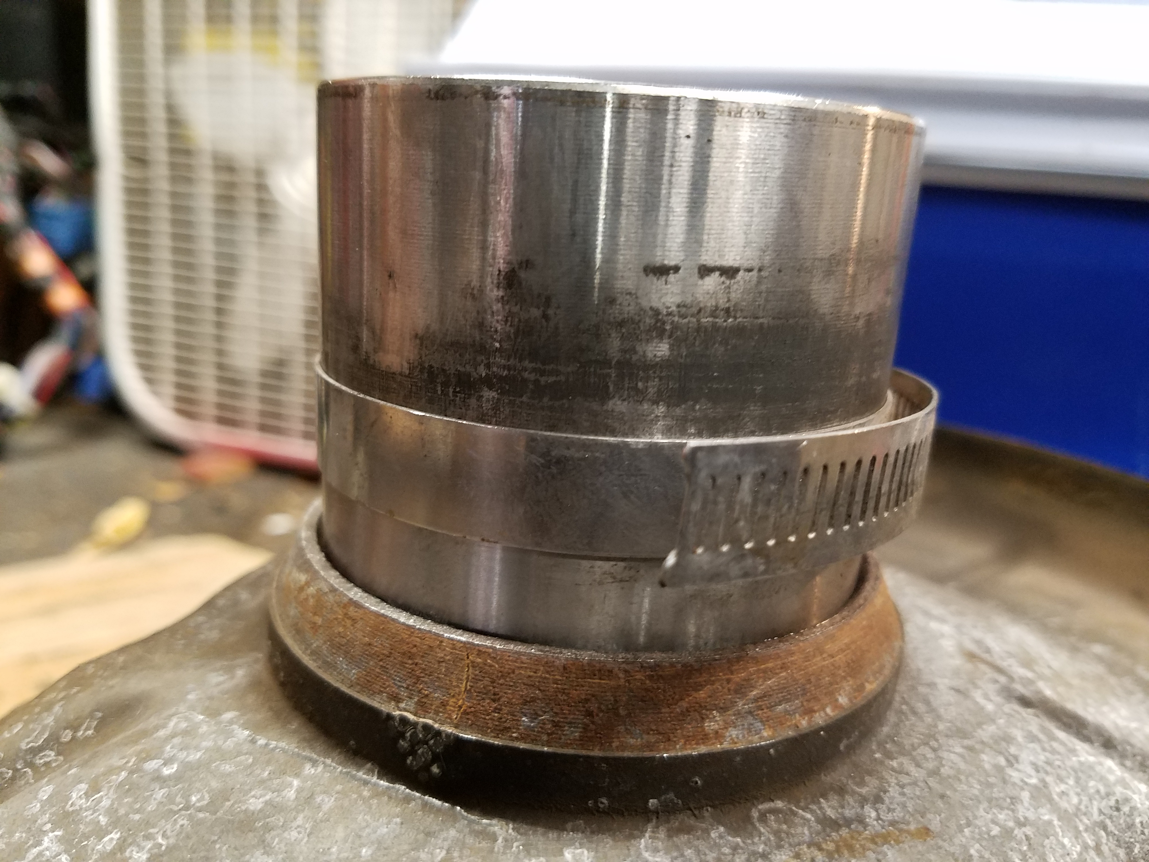
A block of wood on top of the old bearing will help tap it evenly but hard metal to metal contact is really what it needs to drive it in. I periodically checked the inner race to see if it spun normally. If it's going in straight you should have no problems. Once it's a 1/2" in, it should keep itself lined up.
Once it's in, I just reused the original circlip after a bit of wire wheeling to clean it up.
No pics of the last steps, but basically you are then doing the same thing with the hub into the bearing. The IMPORTANT thing to do here is to support the inner bearing race from below as you tap in the hub from above. If you don't, the pressure from hub slipping into the bearing will be put on the bearings themselves. This will probably not give you great life out of the bearings. Again, keep spinning the hub and bearing to ensure there is no resistance as you tap it in.
Final install of hub
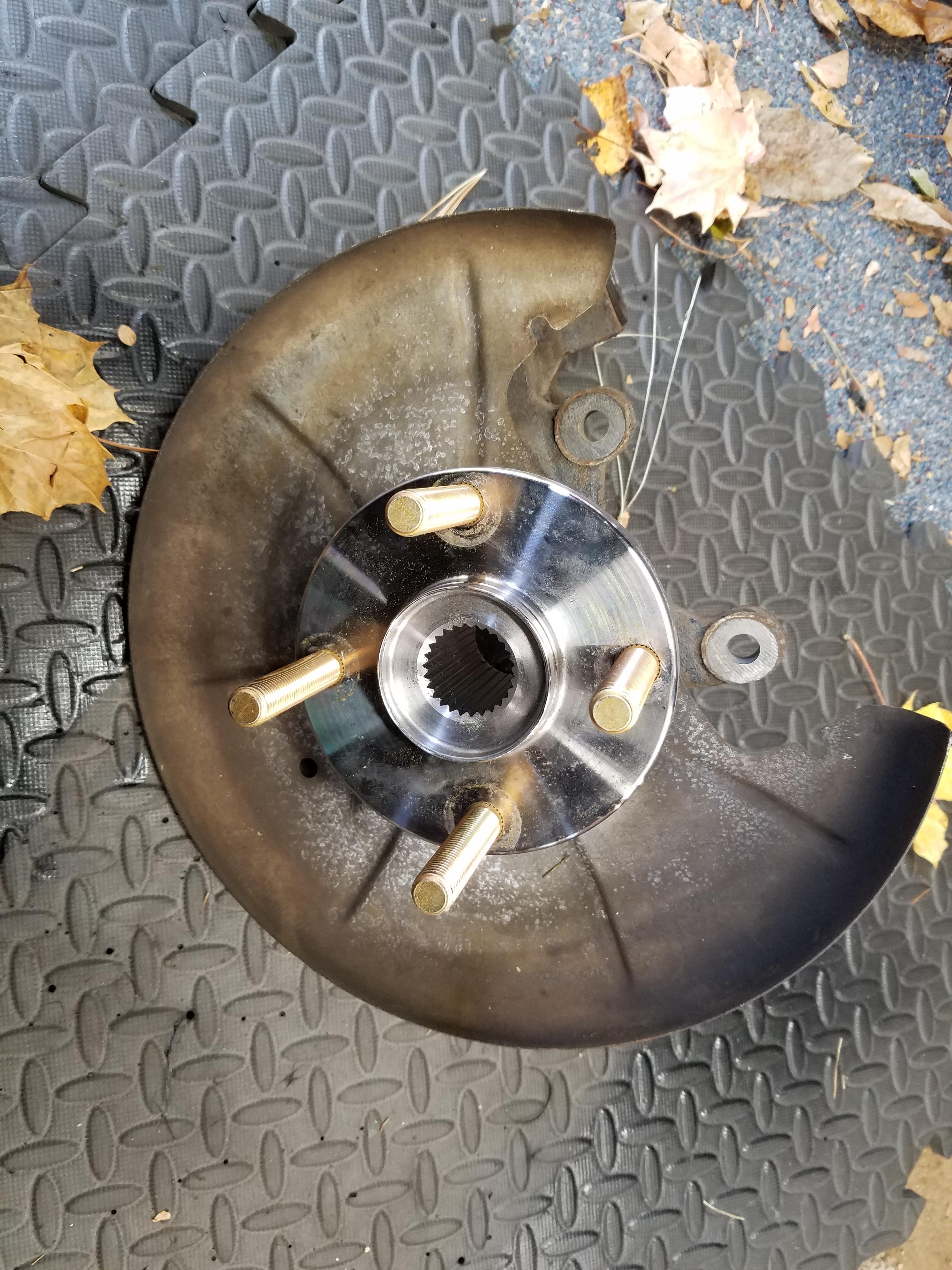
Don't forget to include the dust seal
Here are the parts I used
https://www.amazon.com/gp/product/B000BZ5144
https://www.amazon.com/gp/product/B001542MG0
Bury the hubs and bearings underneath the steak and chicken so your vegetarian wife will never notice.
I used a socket long enough to "catch" the lub bolt and pressed in like so
That is until your vice surrenders with a dull sounding crack
No big deal, that's what a BFH is for. Just make sure you seat the lug bolt head all the way and make sure the threaded part is 90 degrees to the hub face when done and you should be good. This was the easy part.
Use the old bearing (on top) to tap the new bearing into the spindle. I put some light moly grease on the spindle bore. I suppose you could also heat up the spindle with a torch or oven, that might really make it easy. I used a hose clamp to keep them perfectly aligned. If you don't you could nick the new bearing race making it harder to slide into place, or worse damage the rubber seal. Don't **** this up.
A block of wood on top of the old bearing will help tap it evenly but hard metal to metal contact is really what it needs to drive it in. I periodically checked the inner race to see if it spun normally. If it's going in straight you should have no problems. Once it's a 1/2" in, it should keep itself lined up.
Once it's in, I just reused the original circlip after a bit of wire wheeling to clean it up.
No pics of the last steps, but basically you are then doing the same thing with the hub into the bearing. The IMPORTANT thing to do here is to support the inner bearing race from below as you tap in the hub from above. If you don't, the pressure from hub slipping into the bearing will be put on the bearings themselves. This will probably not give you great life out of the bearings. Again, keep spinning the hub and bearing to ensure there is no resistance as you tap it in.
Final install of hub
Don't forget to include the dust seal
Here are the parts I used
https://www.amazon.com/gp/product/B000BZ5144
https://www.amazon.com/gp/product/B001542MG0
The following users liked this post:
Flavaquero (11-08-2016)
11-08-2016, 04:25 PM
#59
V8 Miata Enthusiast
Thread Starter
Started some work on the rear Ford 8.8" diff mount
I've been using this blog post as a guide, it's excellent: MiataV8 Conversion: Rear subframe
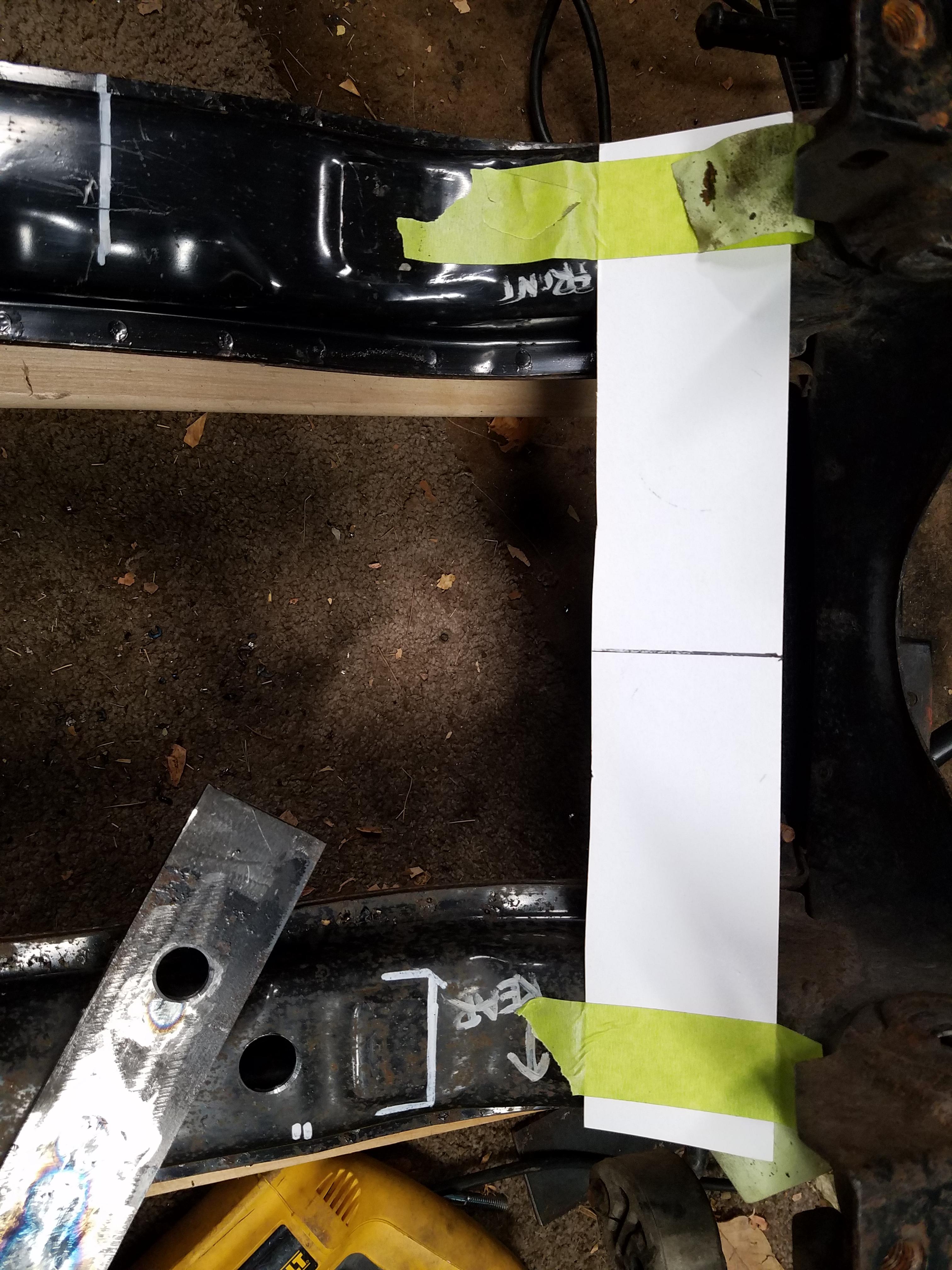
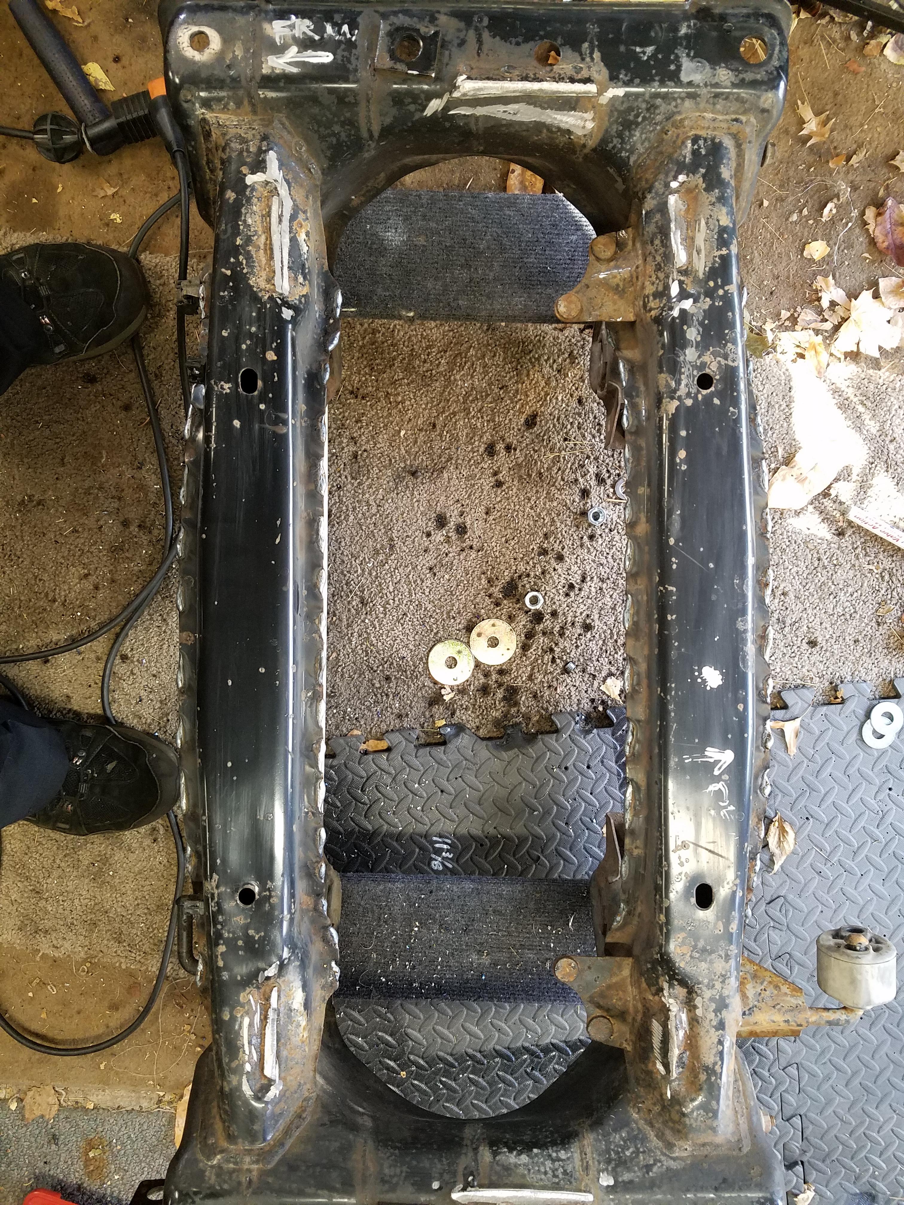
I created a centerline on the subframe by using the control arm mounting holes. Clamped a metal ruler in place, did some math and used a framing square to mark it off. White paint pens be the bomb.
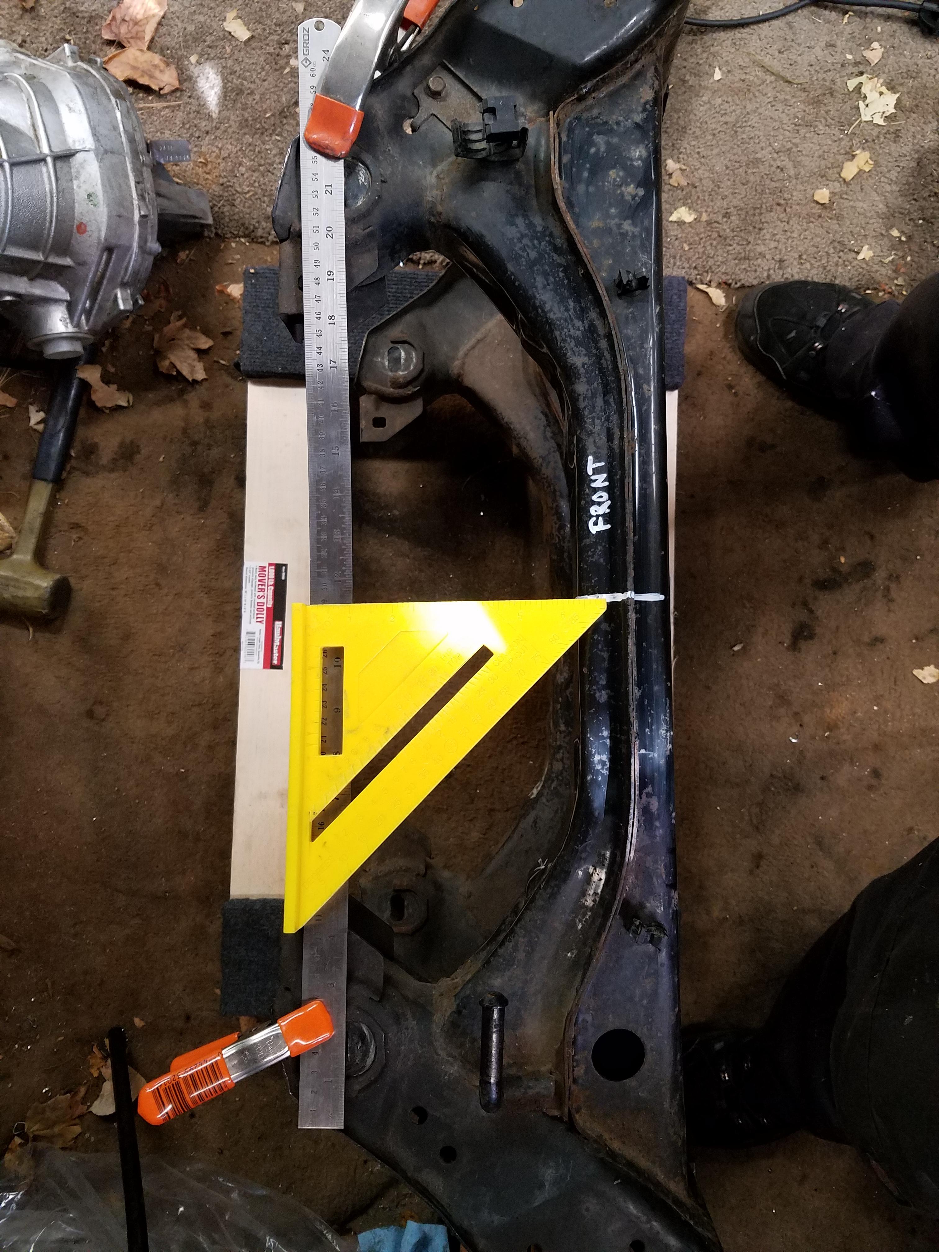
There is enough play in the CV joint that the centerline doesn't need to be exact. But the axles are equal length so you need to leave the same amount of room on either side of the diff for the axle. The pinion mount on the diff (where the driveshaft connects) is not on the centerline of the diff, so be aware of that.
Marked centerline in front and back of subframe
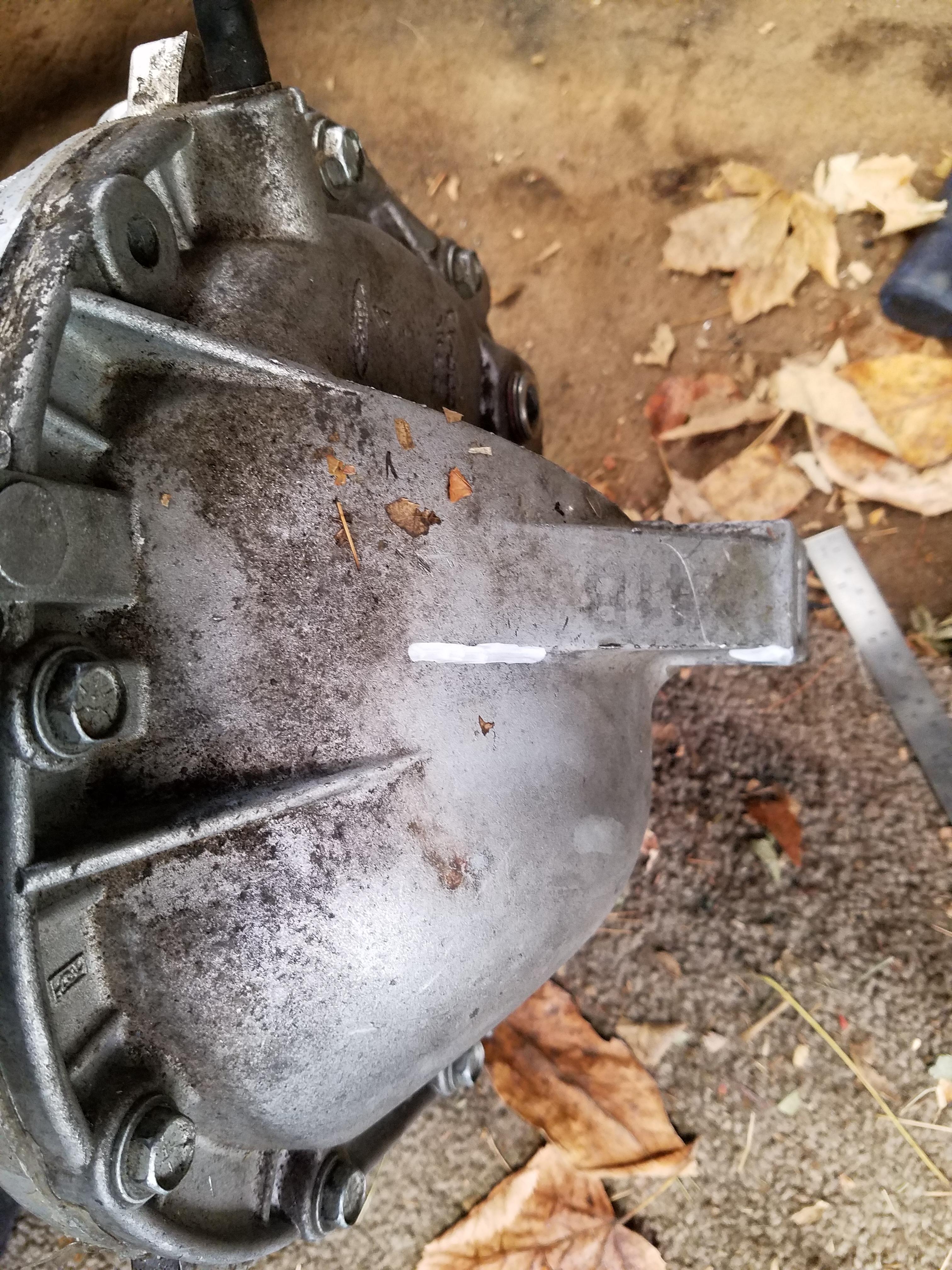
Then I marked a centerline on the diff by using the metal face of the axle holes and some metal straight edges/rulers. I think it was about 11.5" from face to face. Turns out the centerline is right near the rear mounting point on this diff. The diff is out of a 99 Ford Cobra Mustang with the Traction Lok LSD. All aluminum case with some ribbing for strength and the front and back mount points.
With this basic info I laid the diff in place on the subframe and lined up the centerlines on the diff and mount to get some rough ideas. Then I used some measurements I took from the original Miata diff to determine where the axles would fall, front to back, as they connect to the wheels. Turns out the axle centerline is pretty much in the middle of the subframe.
Once I lined those up I had a good idea of where it would sit in the subframe. The only detail would be how high or low it would sit and what the pinion angle would be. This can be adjusted with spacers or washers on either end of the diff once the mounts are created, but my rough measurements think the diff is pretty close to where it needs to be - in relation to the front of the engine. The angle of the trans output should be the same or very close (few degrees) to the diff's pinion flange angle.
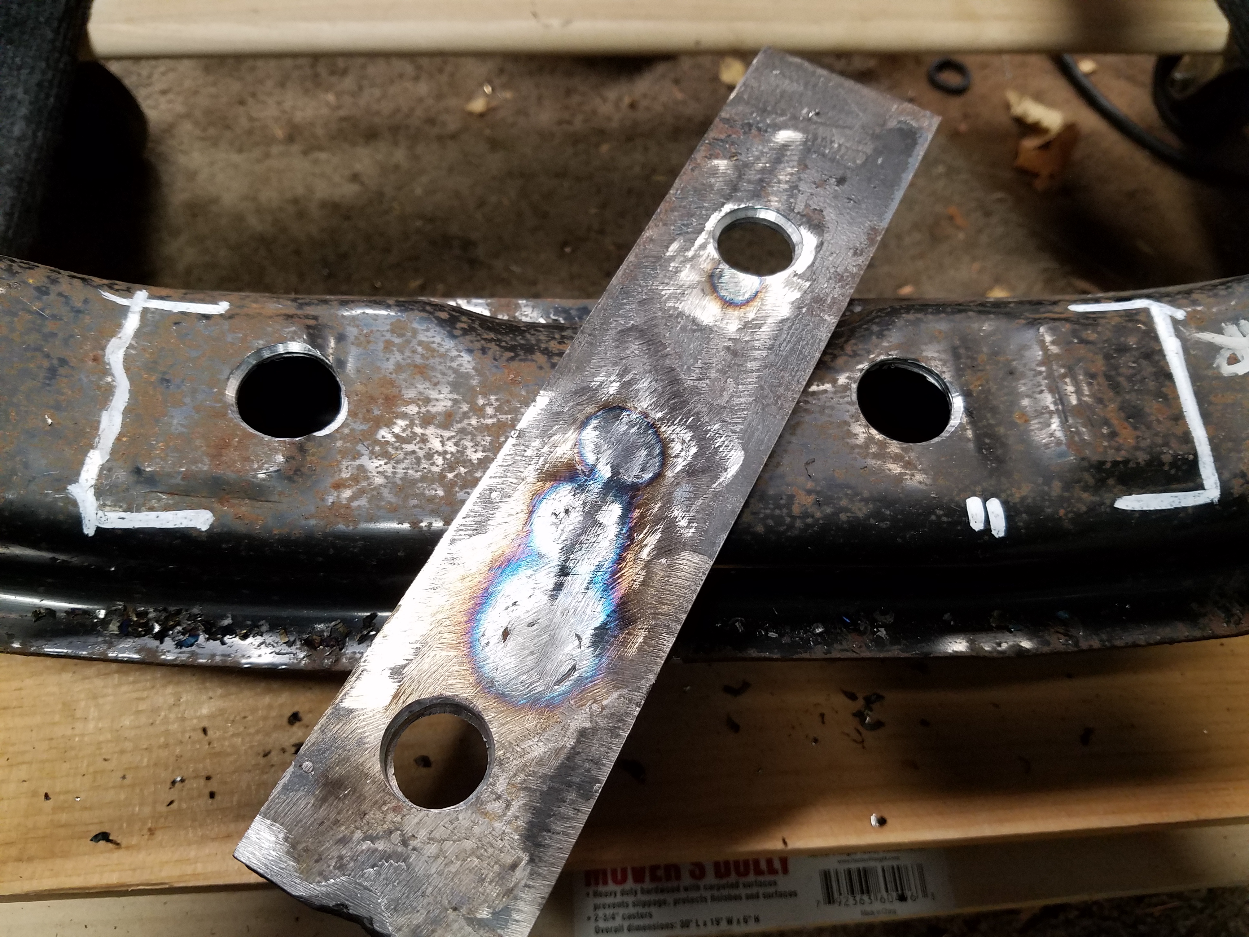
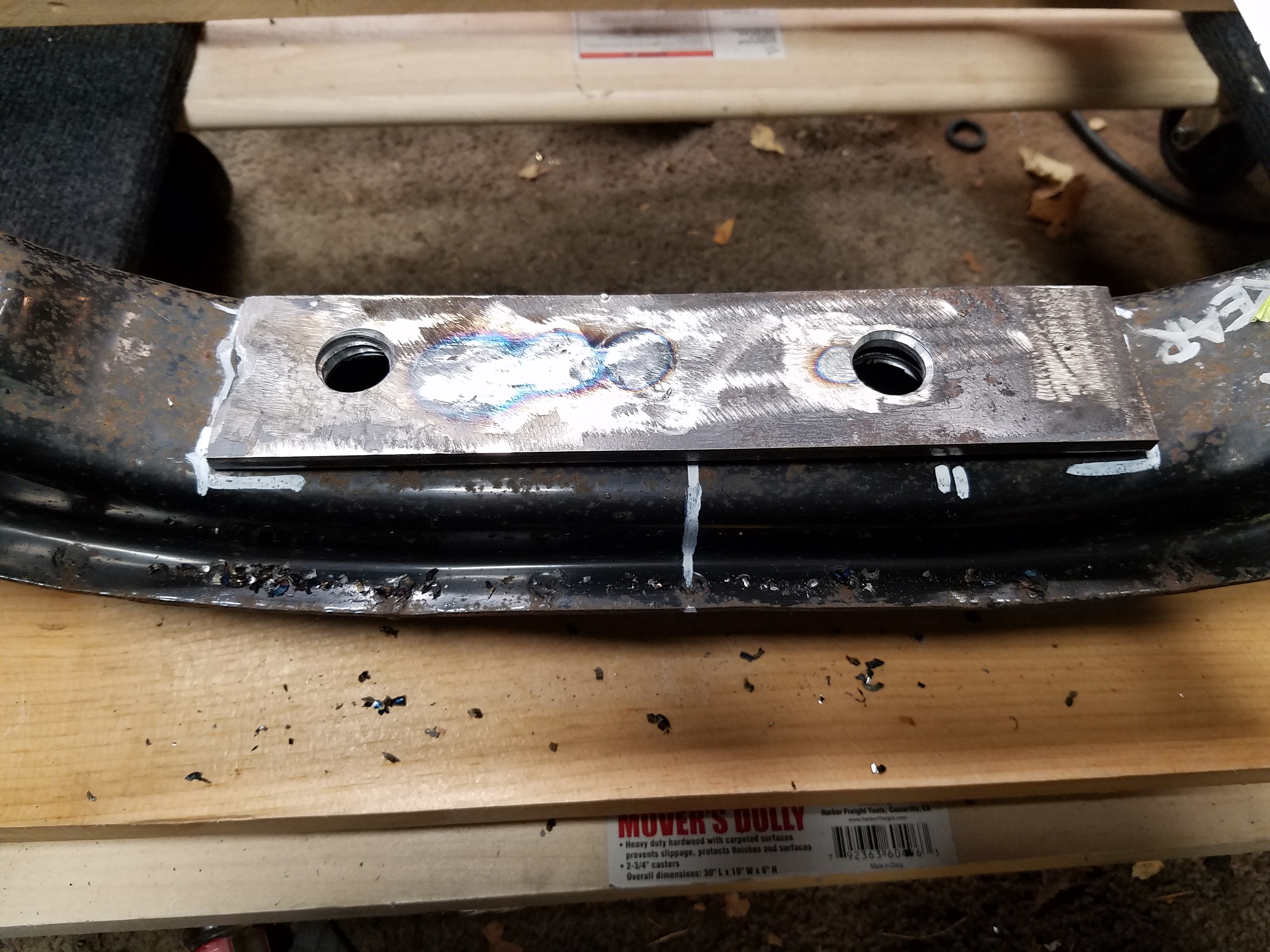
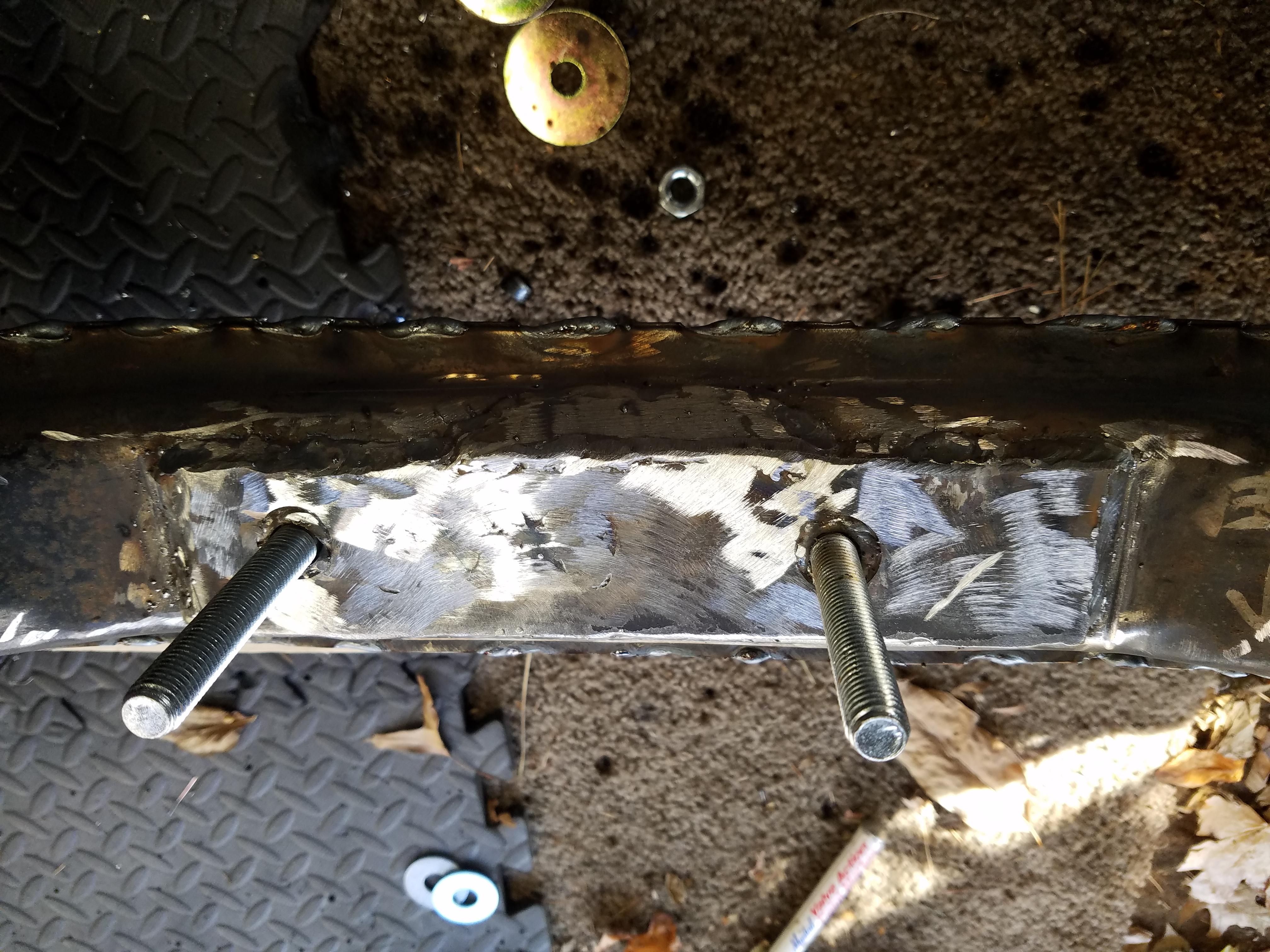
Once I knew this I created some mounts for the rear of the diff
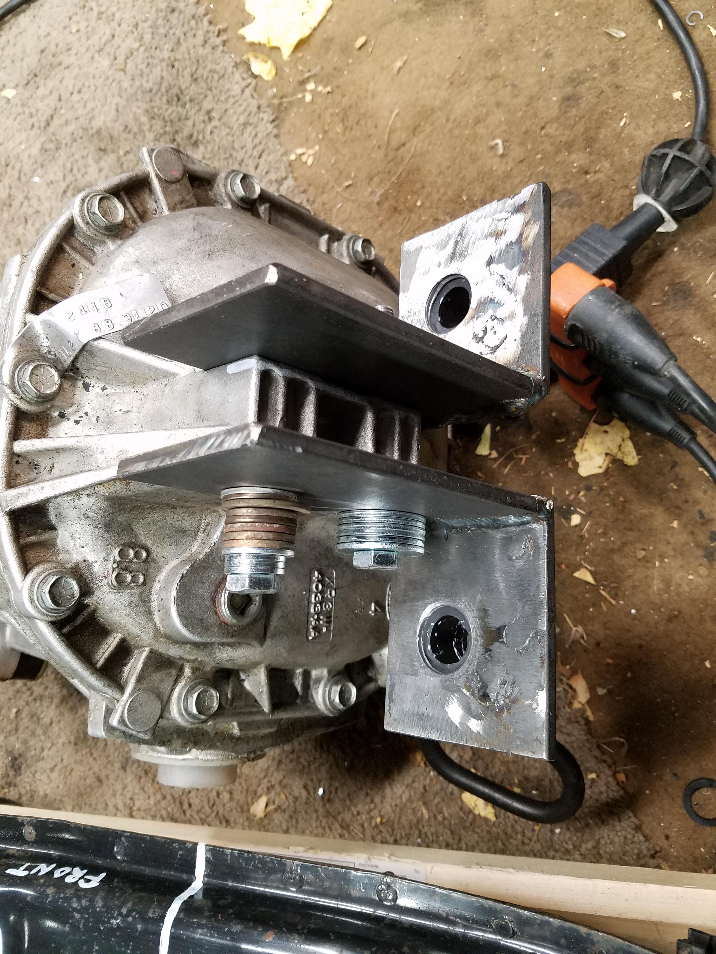
Worked on a strong/thick brace plate that will weld to the subframe where the rear of the diff will mount to. The holes in the subframe are to make room for long 10.9 grade bolt heads that will point up to received the diff mount. This might make more sense once it's all fitted together. I also plan to gusset the L-shaped mounts for strength. And also seam weld the entire subframe, then wire wheel it and POR15 it.
I've been using this blog post as a guide, it's excellent: MiataV8 Conversion: Rear subframe
I created a centerline on the subframe by using the control arm mounting holes. Clamped a metal ruler in place, did some math and used a framing square to mark it off. White paint pens be the bomb.
There is enough play in the CV joint that the centerline doesn't need to be exact. But the axles are equal length so you need to leave the same amount of room on either side of the diff for the axle. The pinion mount on the diff (where the driveshaft connects) is not on the centerline of the diff, so be aware of that.
Marked centerline in front and back of subframe
Then I marked a centerline on the diff by using the metal face of the axle holes and some metal straight edges/rulers. I think it was about 11.5" from face to face. Turns out the centerline is right near the rear mounting point on this diff. The diff is out of a 99 Ford Cobra Mustang with the Traction Lok LSD. All aluminum case with some ribbing for strength and the front and back mount points.
With this basic info I laid the diff in place on the subframe and lined up the centerlines on the diff and mount to get some rough ideas. Then I used some measurements I took from the original Miata diff to determine where the axles would fall, front to back, as they connect to the wheels. Turns out the axle centerline is pretty much in the middle of the subframe.
Once I lined those up I had a good idea of where it would sit in the subframe. The only detail would be how high or low it would sit and what the pinion angle would be. This can be adjusted with spacers or washers on either end of the diff once the mounts are created, but my rough measurements think the diff is pretty close to where it needs to be - in relation to the front of the engine. The angle of the trans output should be the same or very close (few degrees) to the diff's pinion flange angle.
Once I knew this I created some mounts for the rear of the diff
Worked on a strong/thick brace plate that will weld to the subframe where the rear of the diff will mount to. The holes in the subframe are to make room for long 10.9 grade bolt heads that will point up to received the diff mount. This might make more sense once it's all fitted together. I also plan to gusset the L-shaped mounts for strength. And also seam weld the entire subframe, then wire wheel it and POR15 it.
Last edited by pj_mcgarvey; 03-29-2017 at 07:57 PM.
11-08-2016, 04:33 PM
#60
V8 Miata Enthusiast
Thread Starter
Nice progress! Feels good to get a handful of these little projects out of the way doesnt it?
Did you remove the LS1 coolant sensor entirely? The PCM will still need to read from it, so typically most put the miata sensor into the plugged off port on the rear of the passenger side head.
Did you remove the LS1 coolant sensor entirely? The PCM will still need to read from it, so typically most put the miata sensor into the plugged off port on the rear of the passenger side head.
Hmm, I didn't know that about the temp sensor. Just got the PCM back from being modded but haven't looked into that kind of stuff yet. So the PCM still needs the LS1 sensor signal, but the Miata sensor will feed the water temp gauge... makes sense. Thanks!!
Last edited by pj_mcgarvey; 03-29-2017 at 07:57 PM.
11-08-2016, 04:55 PM
#61
V8 Miata Follower

Thanks for the info on the axles. I wonder if anyone has used the 900 hp version and are they worth the extra money. I am looking at 600hp at the flywheel. It is always about the trade off between money and piece of mind. I intend to use the coilovers from V8 Roadsters and do not know if there will be interference issues?
11-08-2016, 06:02 PM
#62
V8 Miata Enthusiast
Thread Starter
Thanks for the info on the axles. I wonder if anyone has used the 900 hp version and are they worth the extra money. I am looking at 600hp at the flywheel. It is always about the trade off between money and piece of mind. I intend to use the coilovers from V8 Roadsters and do not know if there will be interference issues?
11-12-2016, 10:49 PM
#63
V8 Miata Fanatic


PJ - You're making some great progress! Great detail on rear hub work. I now know where to come to if and when I need to revisit my rear axles in the future!
You also have a pretty unique M3/4/5... Like those as well.
You also have a pretty unique M3/4/5... Like those as well.
11-13-2016, 02:46 PM
#64
V8 Miata Enthusiast
Thread Starter
The M3 is one of my favorite cars. It's a great example in very nice shape for almost 160k miles, and with any luck will increase in value during my ownership. Though I think it's jealous of all the time I'm spending on the Miata - lol.
11-13-2016, 03:11 PM
#65
V8 Miata Enthusiast
Thread Starter
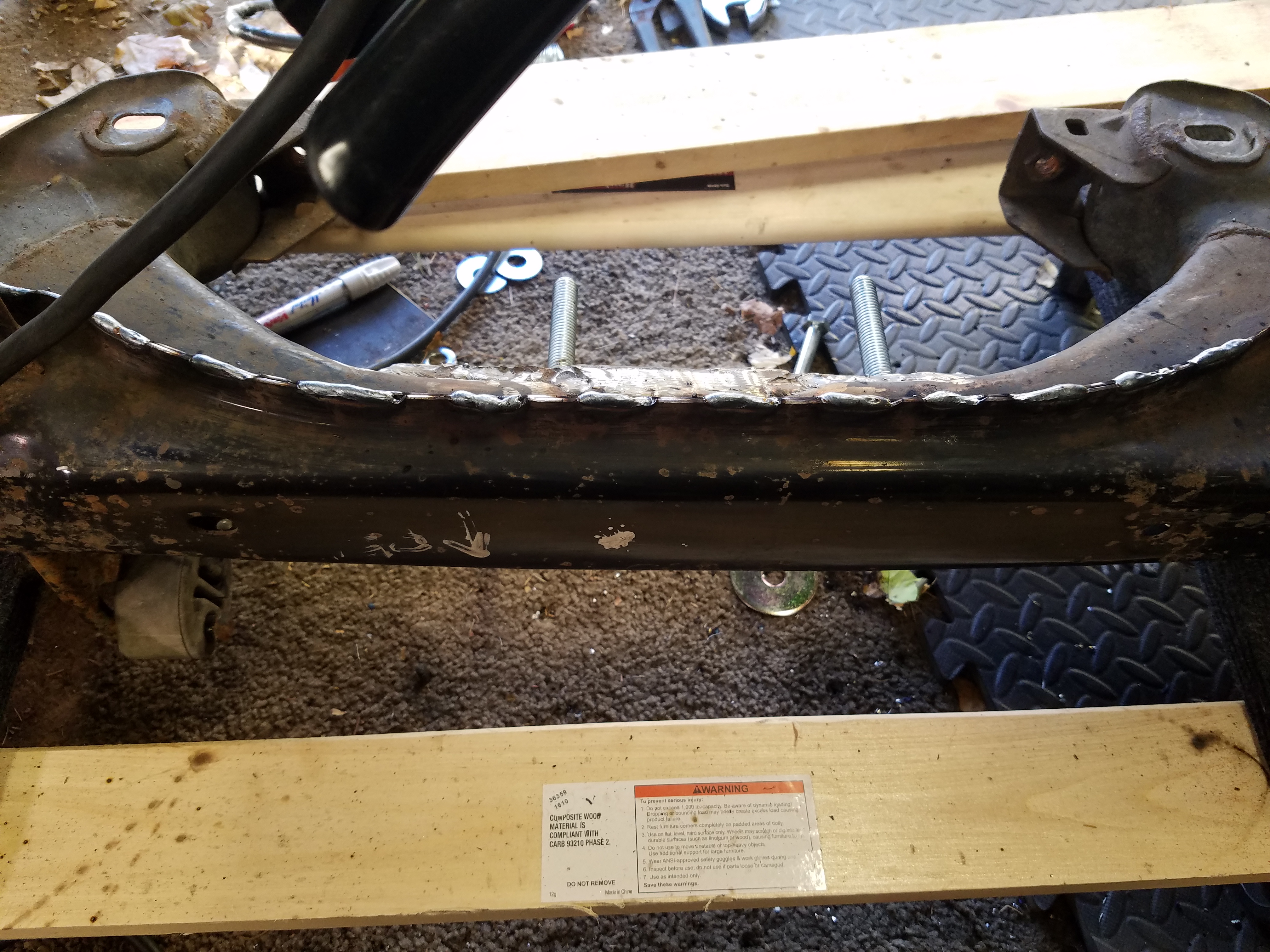
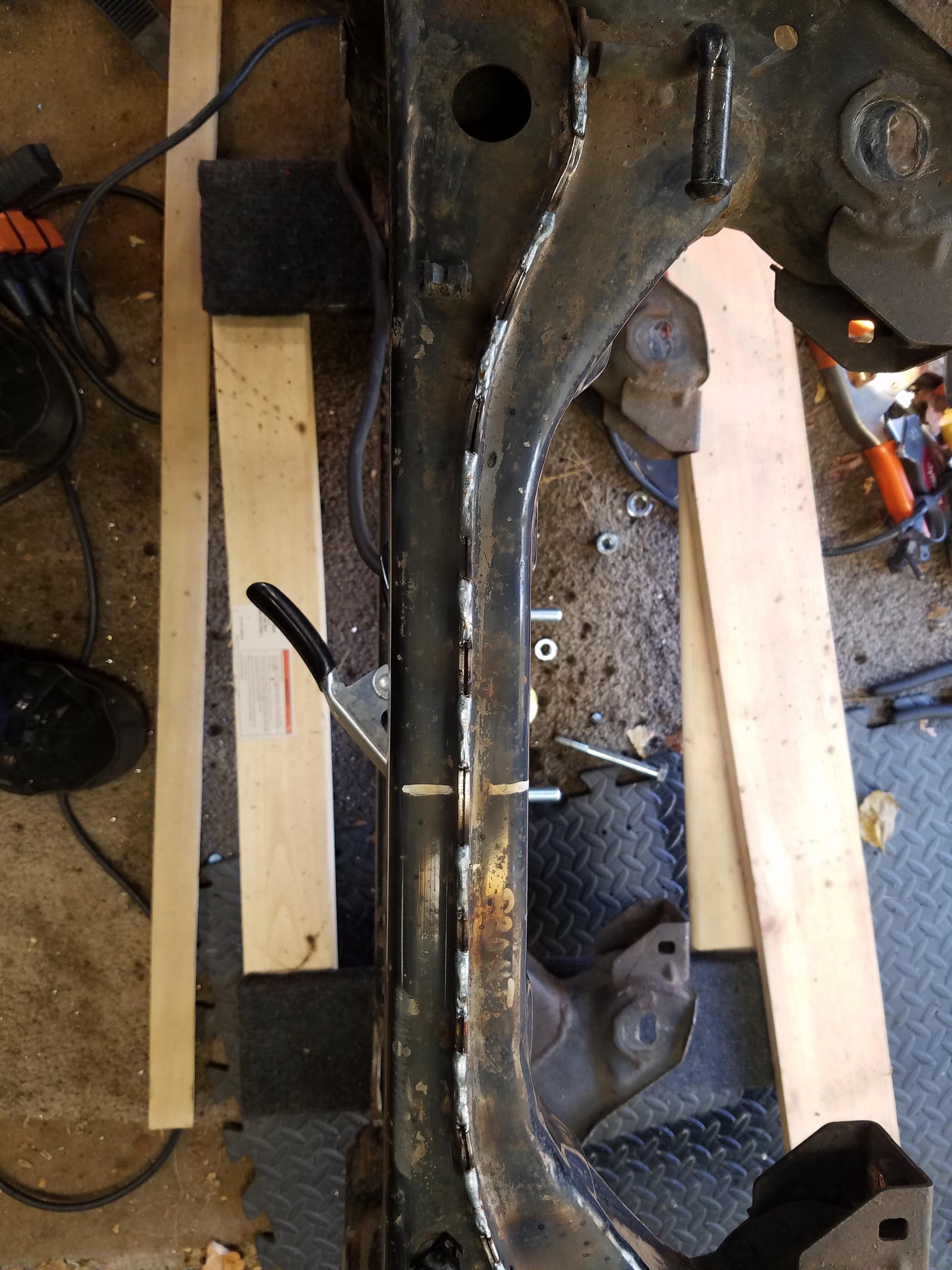
Picking up where I left off on the subframe work. After getting the large bolts tacked to the plate in the right place for the diff brackets, I welded the large plate to the subframe. Now I can drop in the diff and bolt it (nut it?) down.
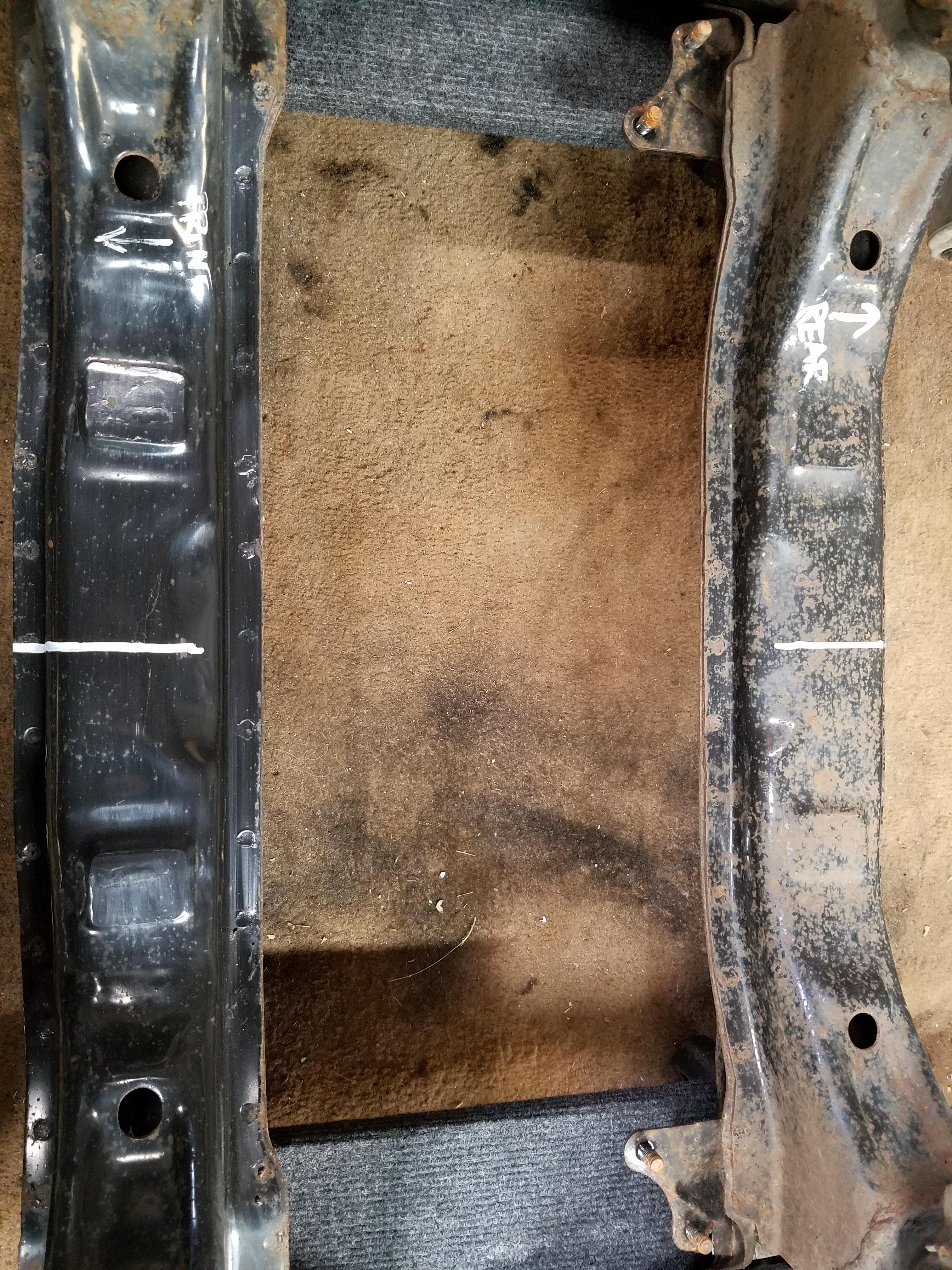
Before that I did some seam welding of the rear subframe where there are pinch welds along the length of the two "beams" which will be carrying alot of the torque load as the diff wants to twist under power. All of the other connections in the subframe appear to be fully welded
I will be wire wheeling the whole subframe and doing POR 15 on the whole thing once all the welding and fabrication are done.
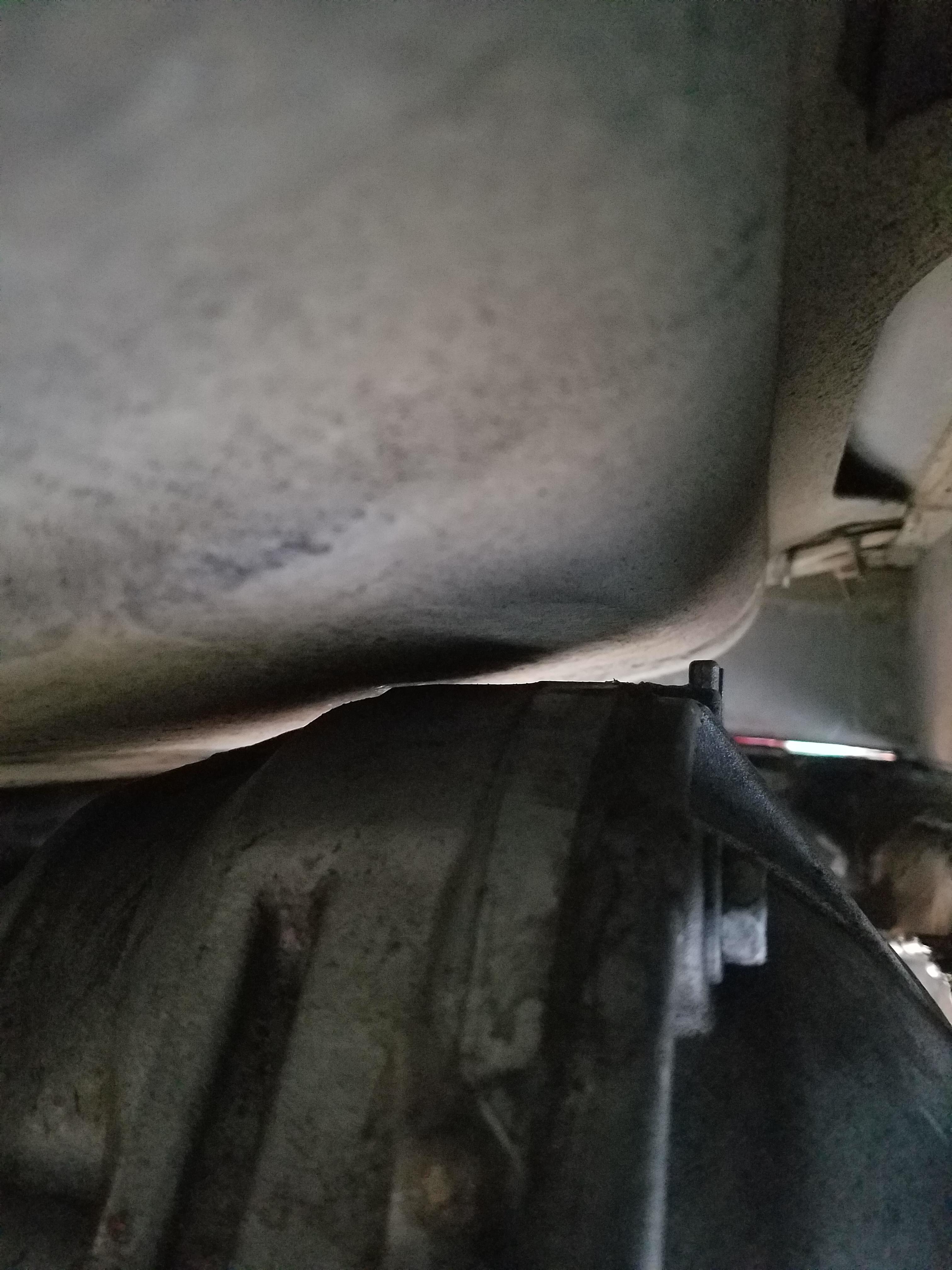
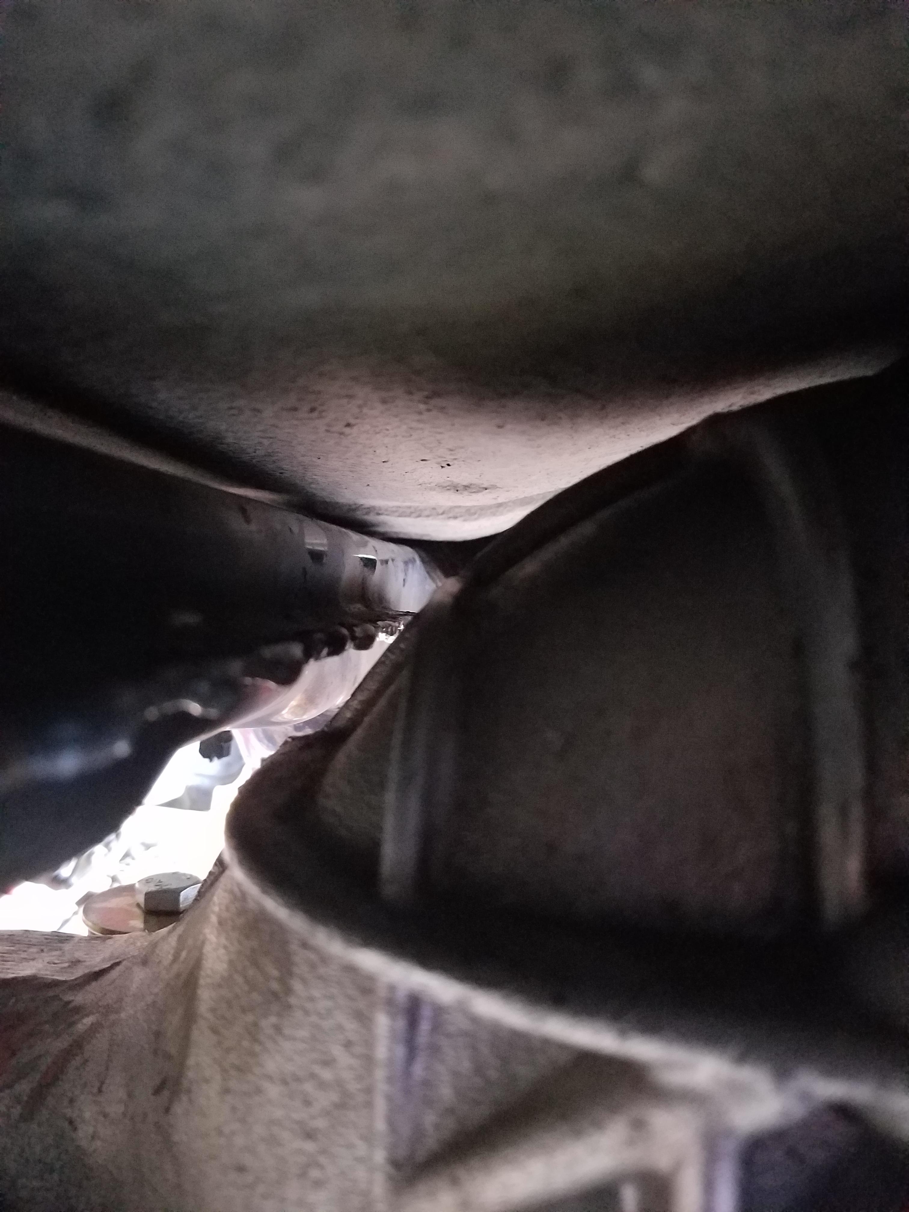
Big moment seeing the pumpkin up in there.
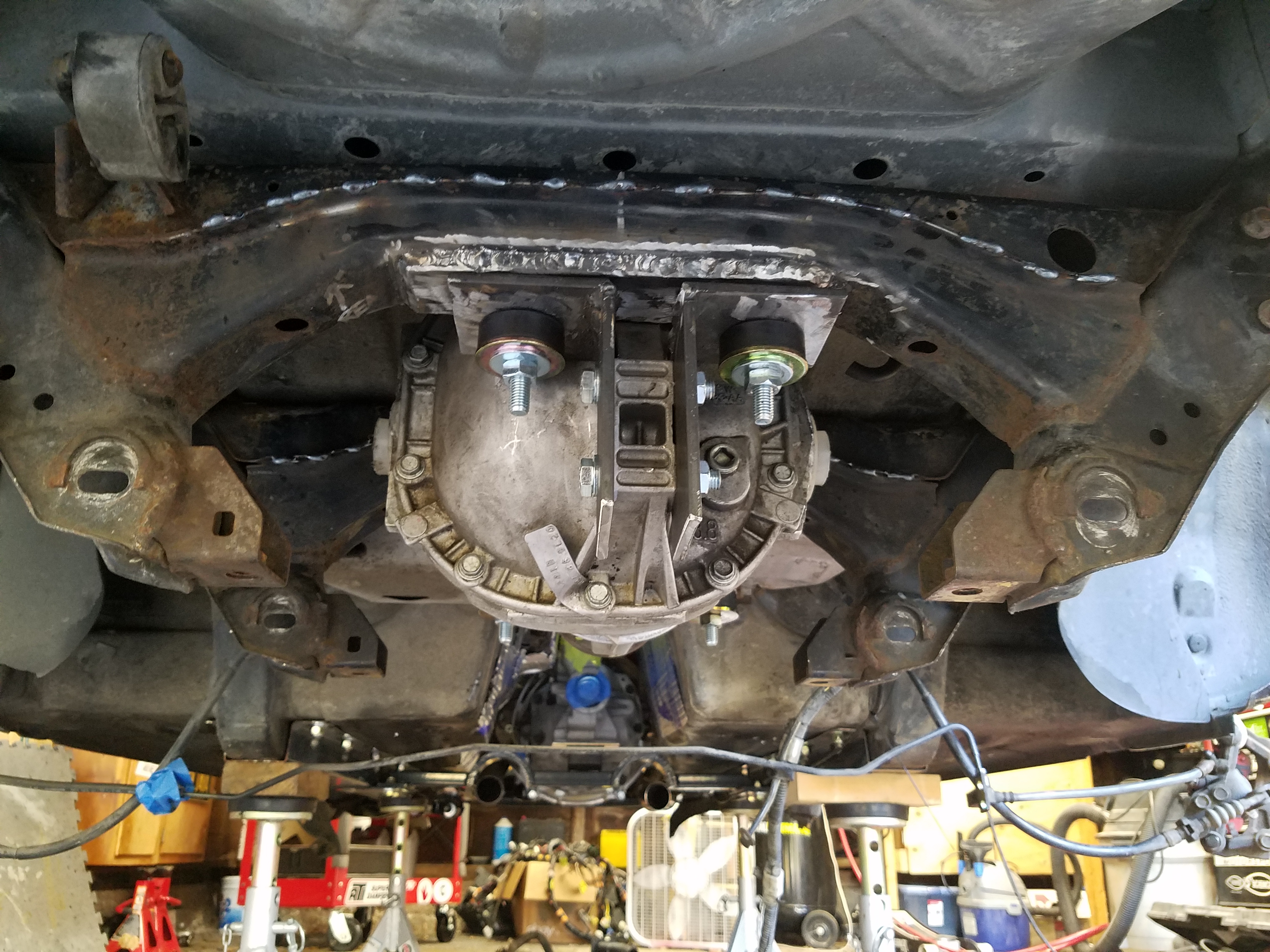
Some shots of the fitment. Looks like I nailed the clearance on the underside of the car. This is with no mounts on the front of the diff yet so I can move the front of the diff up and down to get my pinion angle and clearances right.
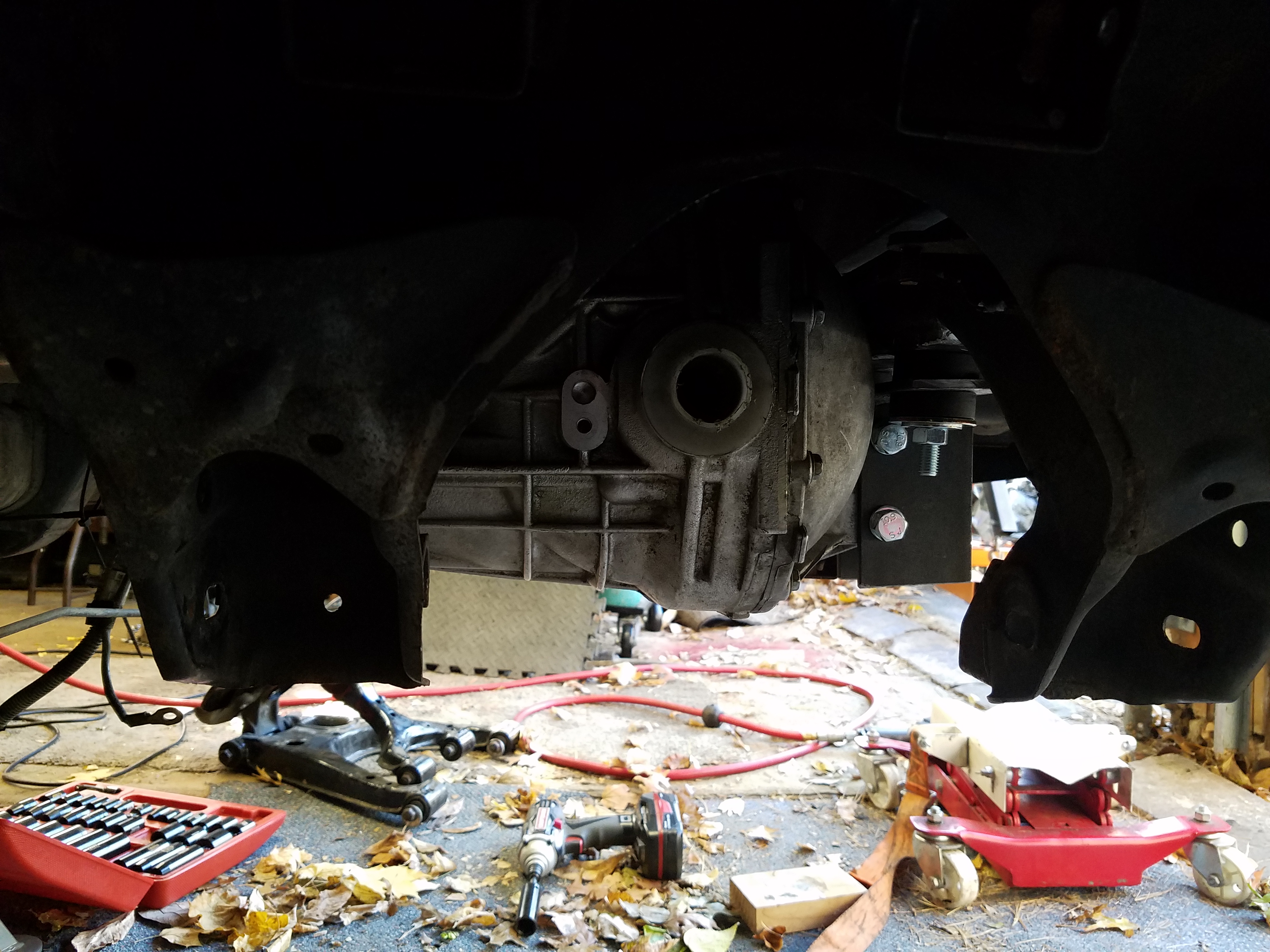
There is plenty of information regarding pinion angle such as Pinion Angle - Wolfe Race Craft. Sites like this and other info all seem to recommend keeping it under 3 degrees. You can take the measurement of the front of the engine on the flats of the crank damper, or at the rear of the trans housing where the output shaft is. I would recommend the the furthest rear point b/c I saw a difference of about 1-2 degrees between the damper and rear of the trans.
I seem to have a downward angle at the trans of 1 degree, and 3 degrees upward at the diff, so I should be in a safe zone right now with my rough setup. At this point I took some measurements for my driveshaft which I will order on Monday from DriveShaft Shop. I want to make sure the driveshaft to Diff adapter won't have any clearance issues with the underside of the fuel tank where there is a bumpout.
Anyone have other suggestions on custom driveshaft options they've used?
Before that I did some seam welding of the rear subframe where there are pinch welds along the length of the two "beams" which will be carrying alot of the torque load as the diff wants to twist under power. All of the other connections in the subframe appear to be fully welded
I will be wire wheeling the whole subframe and doing POR 15 on the whole thing once all the welding and fabrication are done.
Big moment seeing the pumpkin up in there.
Some shots of the fitment. Looks like I nailed the clearance on the underside of the car. This is with no mounts on the front of the diff yet so I can move the front of the diff up and down to get my pinion angle and clearances right.
There is plenty of information regarding pinion angle such as Pinion Angle - Wolfe Race Craft. Sites like this and other info all seem to recommend keeping it under 3 degrees. You can take the measurement of the front of the engine on the flats of the crank damper, or at the rear of the trans housing where the output shaft is. I would recommend the the furthest rear point b/c I saw a difference of about 1-2 degrees between the damper and rear of the trans.
I seem to have a downward angle at the trans of 1 degree, and 3 degrees upward at the diff, so I should be in a safe zone right now with my rough setup. At this point I took some measurements for my driveshaft which I will order on Monday from DriveShaft Shop. I want to make sure the driveshaft to Diff adapter won't have any clearance issues with the underside of the fuel tank where there is a bumpout.
Anyone have other suggestions on custom driveshaft options they've used?
11-13-2016, 03:40 PM
#66
V8 Miata Enthusiast
Thread Starter
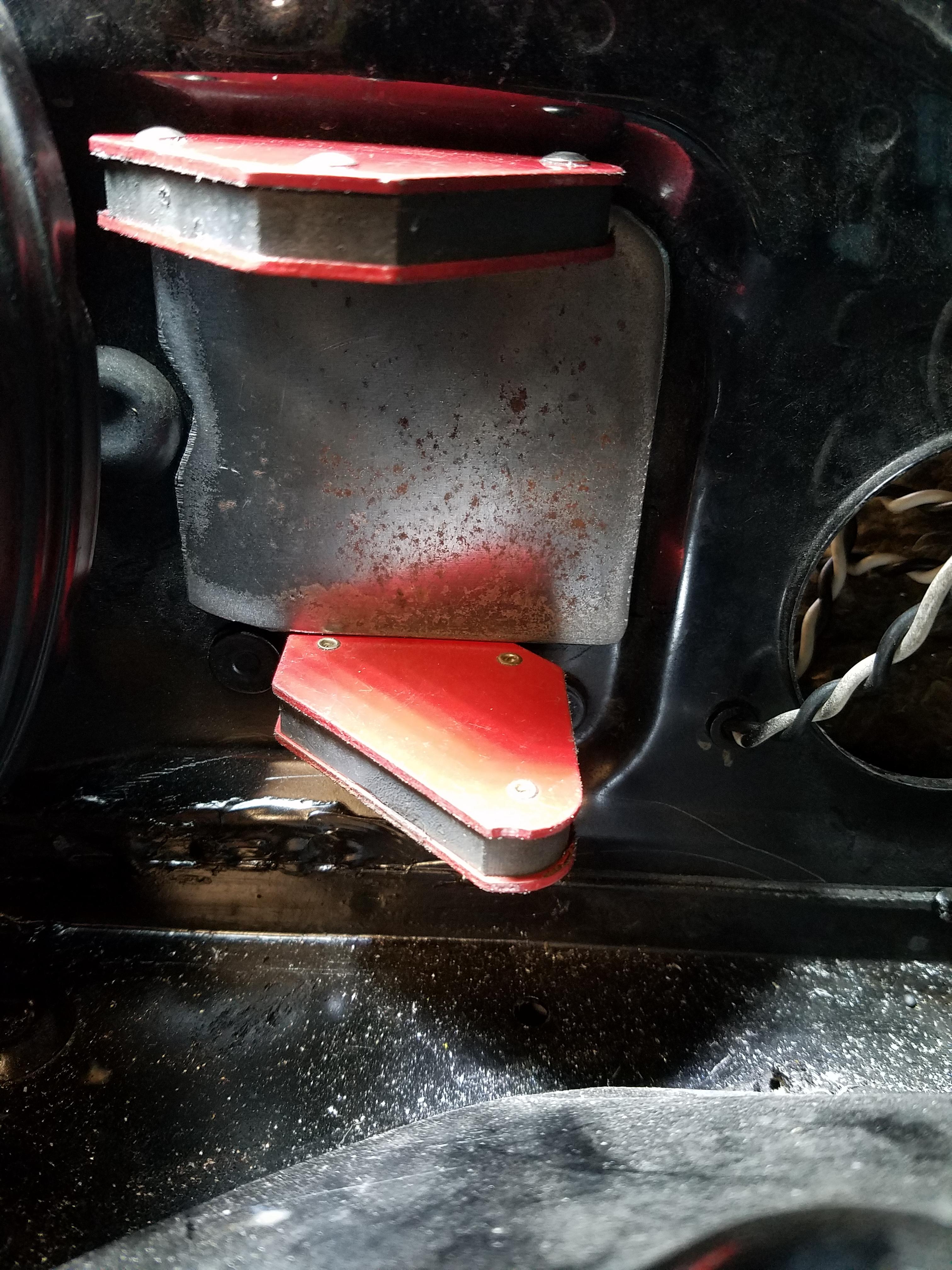
Started some work on the fuel system by installing the upgraded Deatschworks DW200 pump. No pics of the pump installed, but this is it
Install was pretty straight forwrard, it includes everything you need for install into the Miata. One thing I was unsure about was how to make the wiring harness connection. Where I splice the new pump wiring harness into the old wiring, I wasn't sure if I should use any heat shrink tubing or anything non-metal for fear the rubber or insulation might not be made for contact with fuel and degrades and ends up as junk in your fuel tank. The instructions with the pump quickly glossed over this so I made a phone call to them, which has not been returned yet.
I made the connections with bare metal butt connectors (insulation removed) and staggered them so they won't make contact with each other once they are bundled back together. Since there other connectors in the tank that are exposed to fuel without insulation, I feel confident this will be fine.
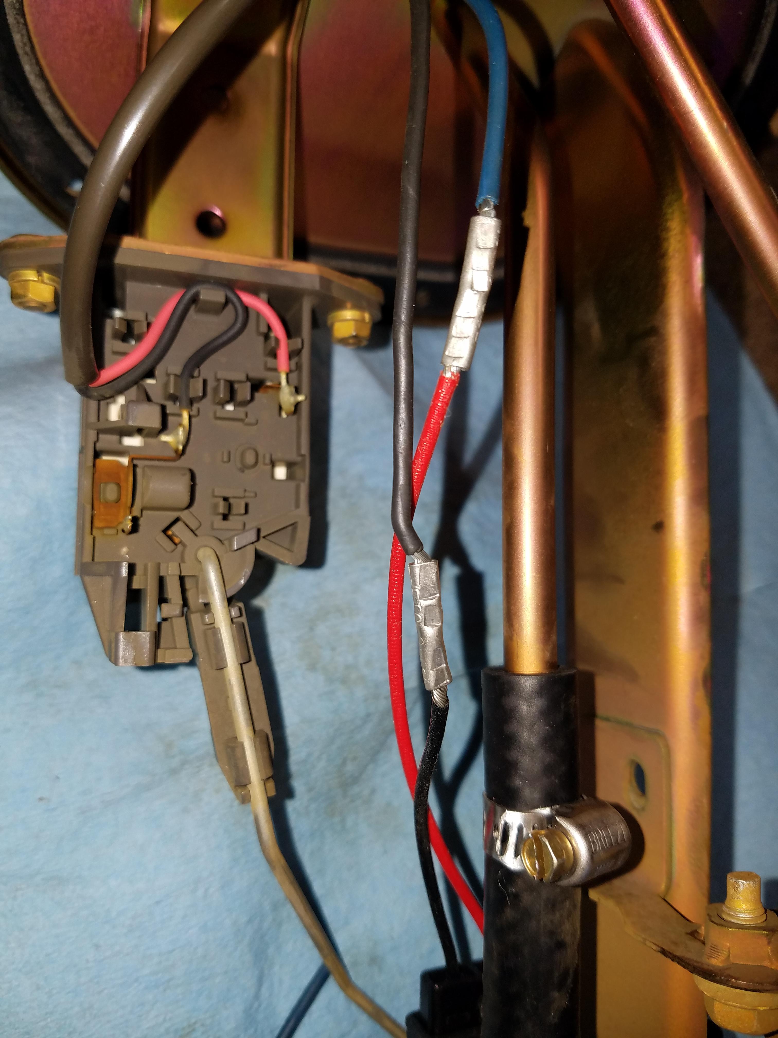
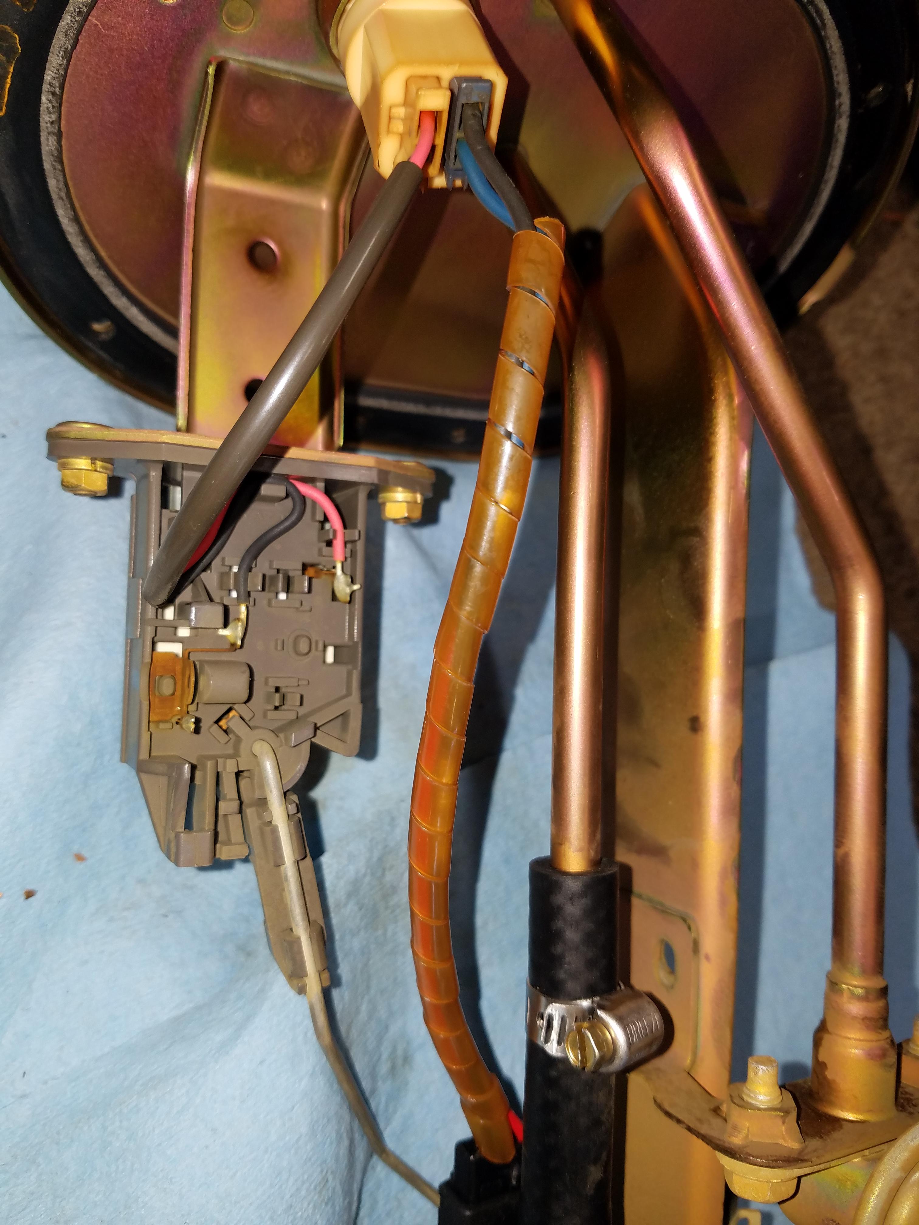
This is the rubber covering that goes back over the wires to keep them together and from chafing on any of the other parts.
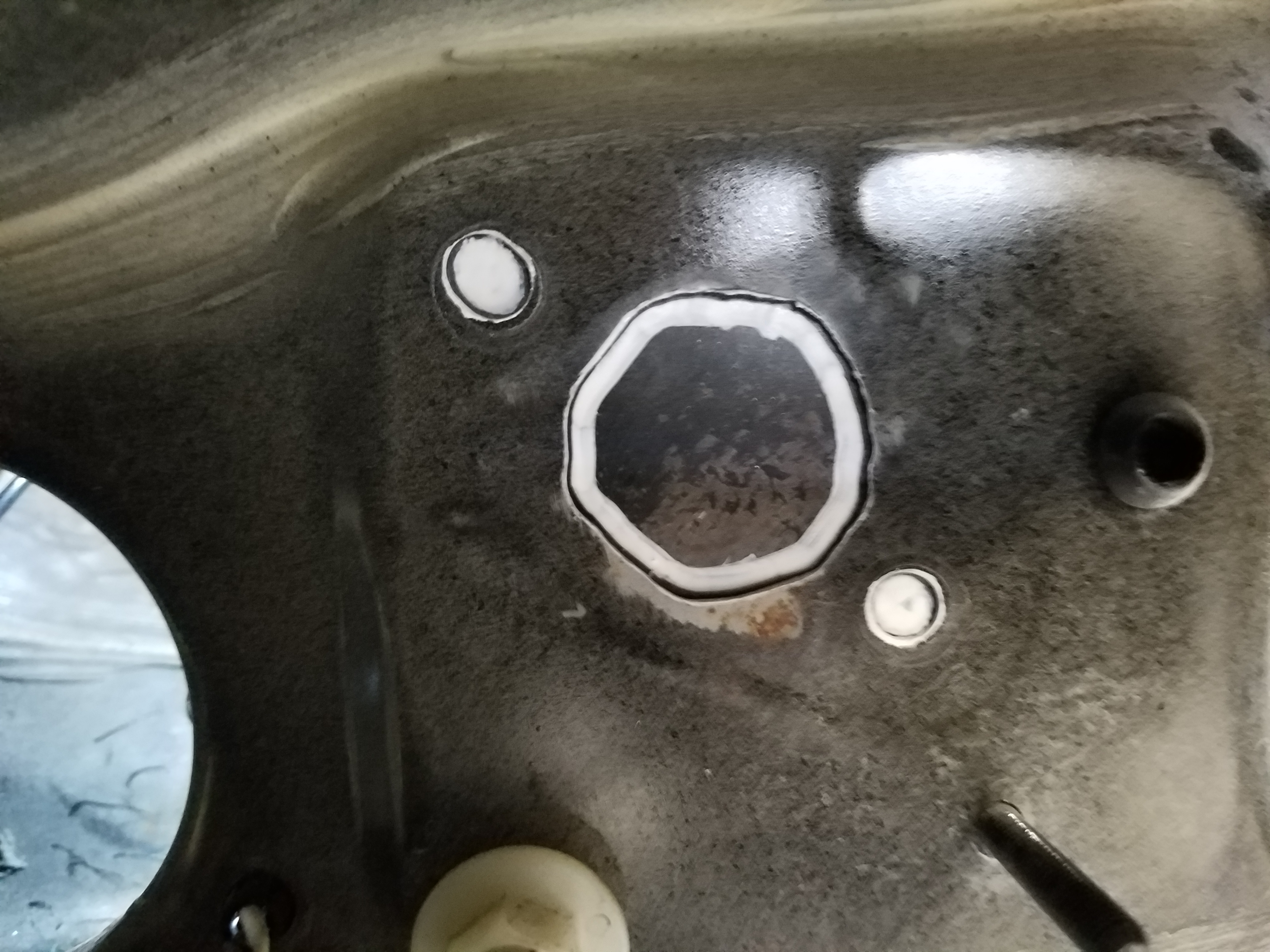
Since I'll be adding the Corvette fuel filter/regulator combo everyone else uses, we don't need to regulating fuel pressure in the tank. I think I read this somewhere, but may need to double check my research.
One concern is what do with the disconnected line that removes about 6" of the return line.
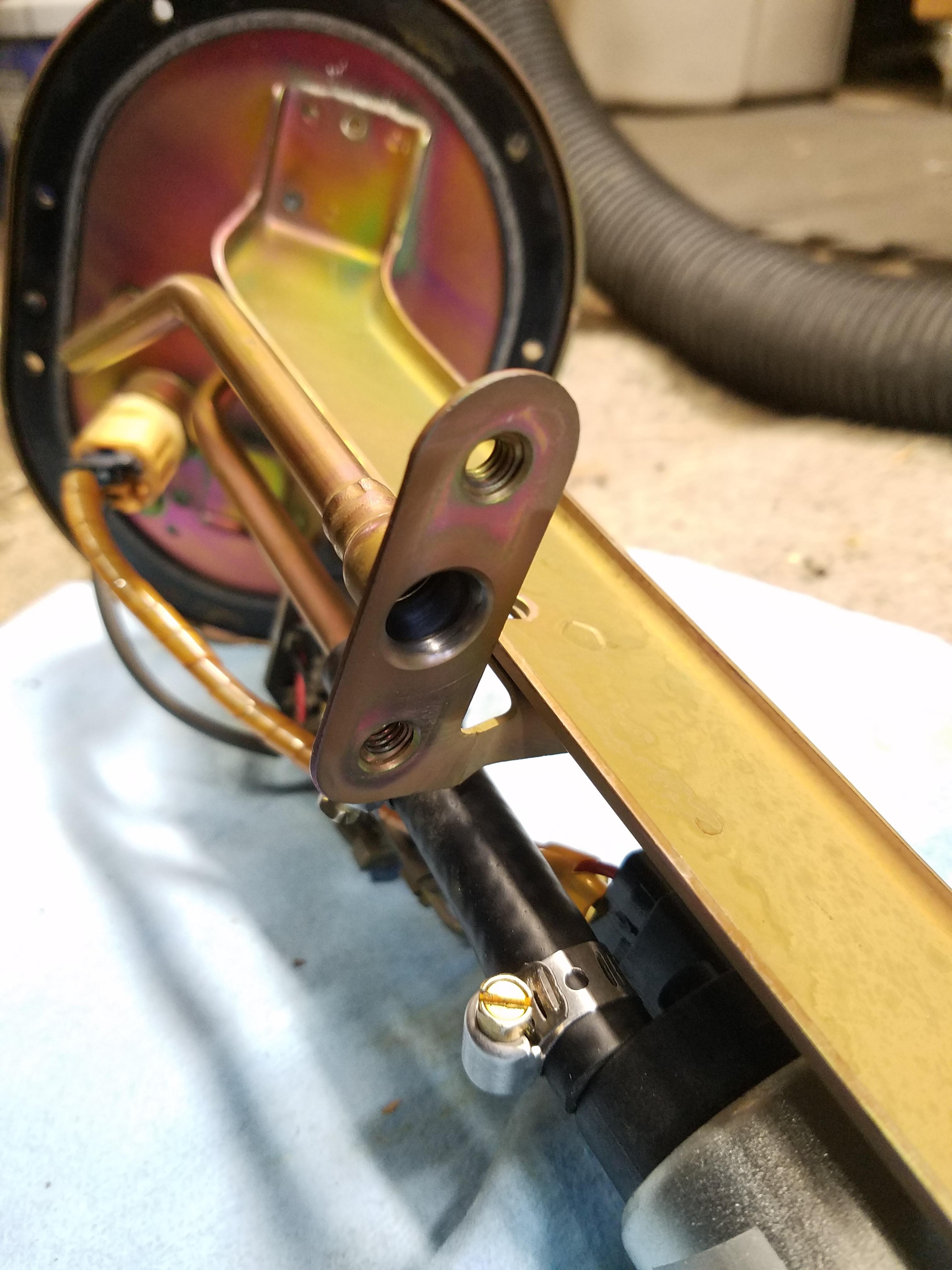
The fuel will make its way back to the tank, but my guess is that you want the return to end near the bottom of the tank - maybe to prevent extra fuel sloshing? I double checked the Flyin Miata swap instructions, and they do not seem to make any concern about removing the fuel regulator hole open: "On NBs only, remove the FPR on the fuel pump assembly (4) and leave the resulting hole open."
Put the assembly back in the tank and attached the blue fuel adapter fittings you see to make them into a -6 AN connection.
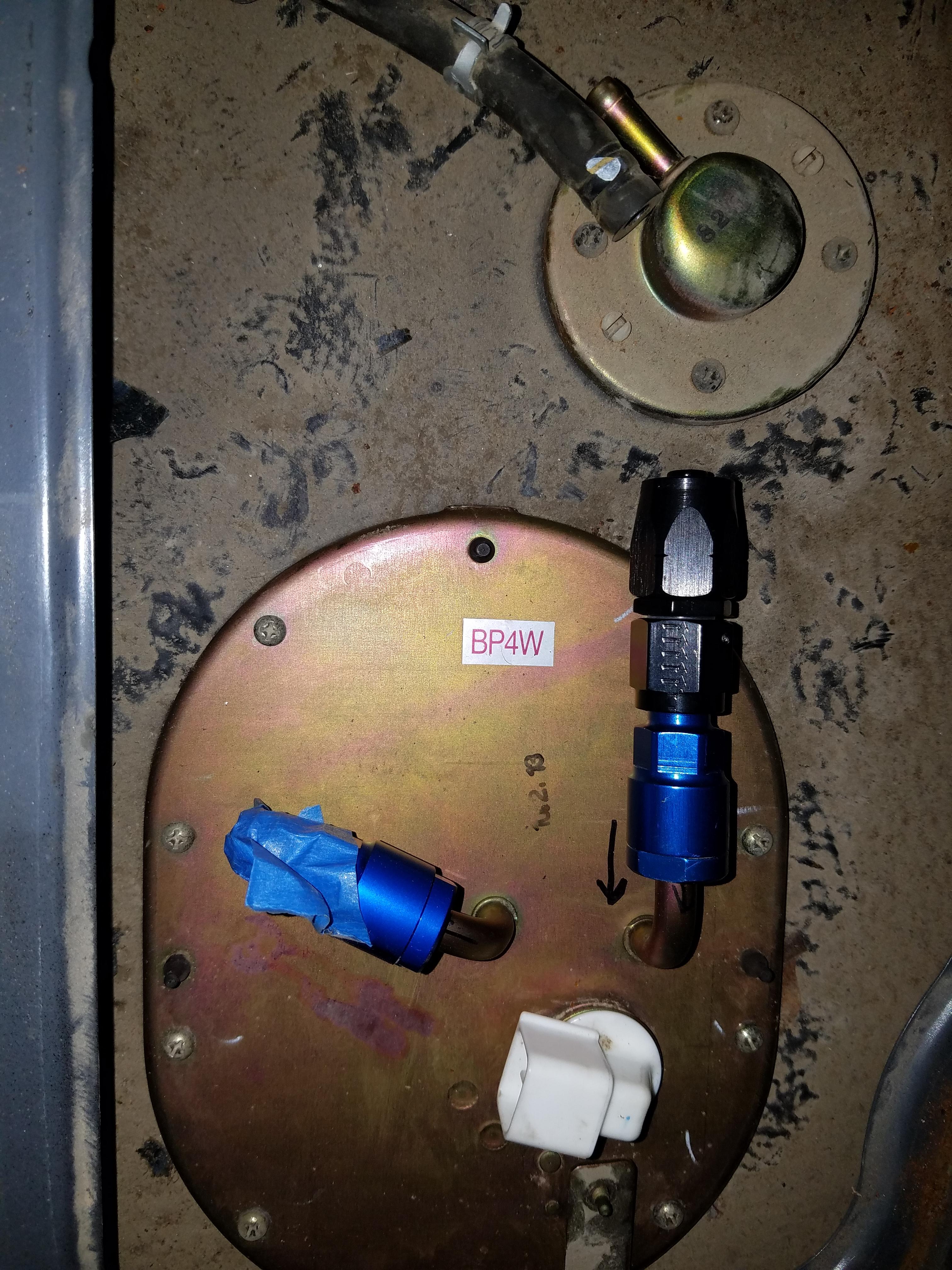
Going to pick up some 45 degree hose ends to work around the other stuff on top of the fuel tank you see.
Install was pretty straight forwrard, it includes everything you need for install into the Miata. One thing I was unsure about was how to make the wiring harness connection. Where I splice the new pump wiring harness into the old wiring, I wasn't sure if I should use any heat shrink tubing or anything non-metal for fear the rubber or insulation might not be made for contact with fuel and degrades and ends up as junk in your fuel tank. The instructions with the pump quickly glossed over this so I made a phone call to them, which has not been returned yet.
I made the connections with bare metal butt connectors (insulation removed) and staggered them so they won't make contact with each other once they are bundled back together. Since there other connectors in the tank that are exposed to fuel without insulation, I feel confident this will be fine.
This is the rubber covering that goes back over the wires to keep them together and from chafing on any of the other parts.
Since I'll be adding the Corvette fuel filter/regulator combo everyone else uses, we don't need to regulating fuel pressure in the tank. I think I read this somewhere, but may need to double check my research.
One concern is what do with the disconnected line that removes about 6" of the return line.
The fuel will make its way back to the tank, but my guess is that you want the return to end near the bottom of the tank - maybe to prevent extra fuel sloshing? I double checked the Flyin Miata swap instructions, and they do not seem to make any concern about removing the fuel regulator hole open: "On NBs only, remove the FPR on the fuel pump assembly (4) and leave the resulting hole open."
Put the assembly back in the tank and attached the blue fuel adapter fittings you see to make them into a -6 AN connection.
Going to pick up some 45 degree hose ends to work around the other stuff on top of the fuel tank you see.
Last edited by pj_mcgarvey; 03-29-2017 at 08:01 PM.
11-13-2016, 03:51 PM
#67
V8 Miata Enthusiast
Thread Starter
Finished up the power steering pump bracket. I just hit it with some matching red spray paint the day before and bolted it up. It's not the prettiest thing but seems to very solidly mount the pump where I need it.
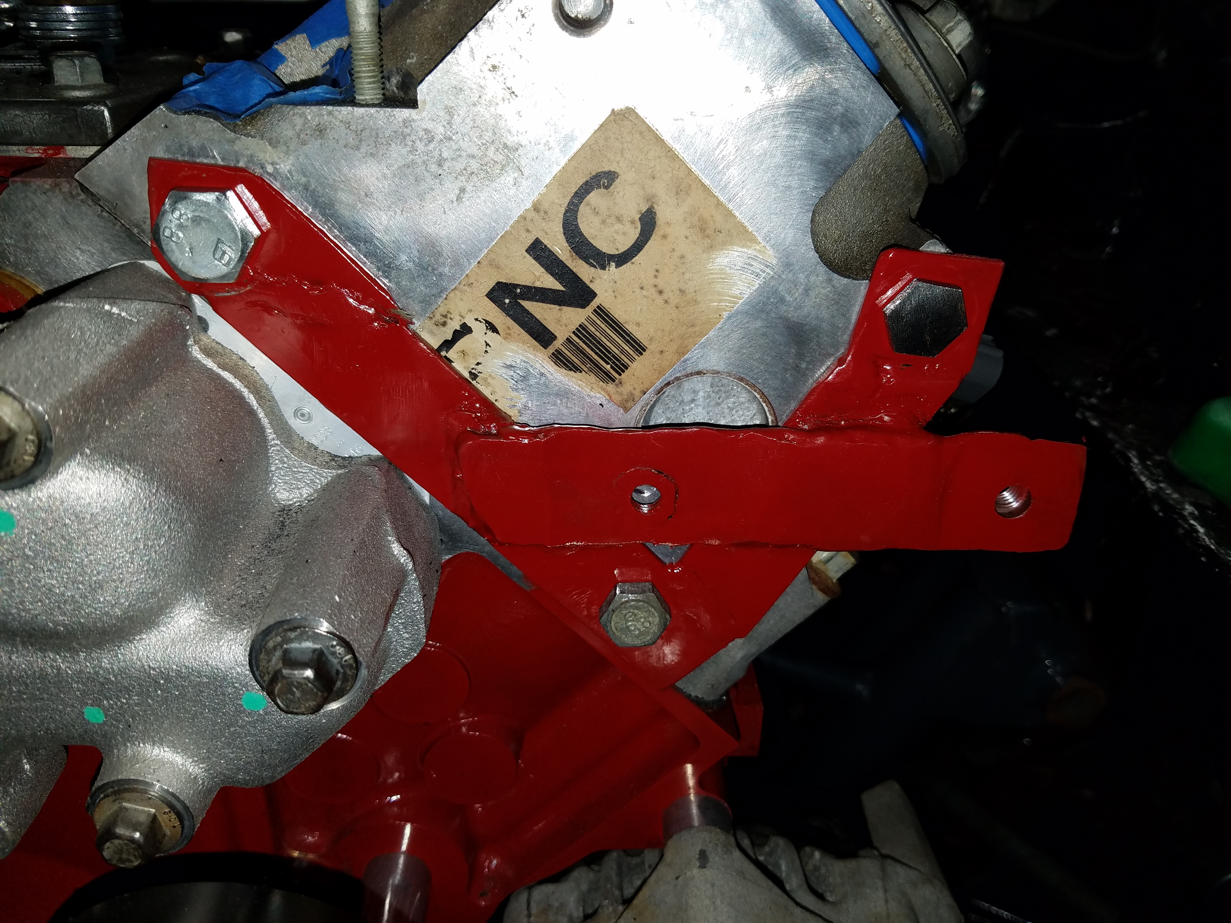
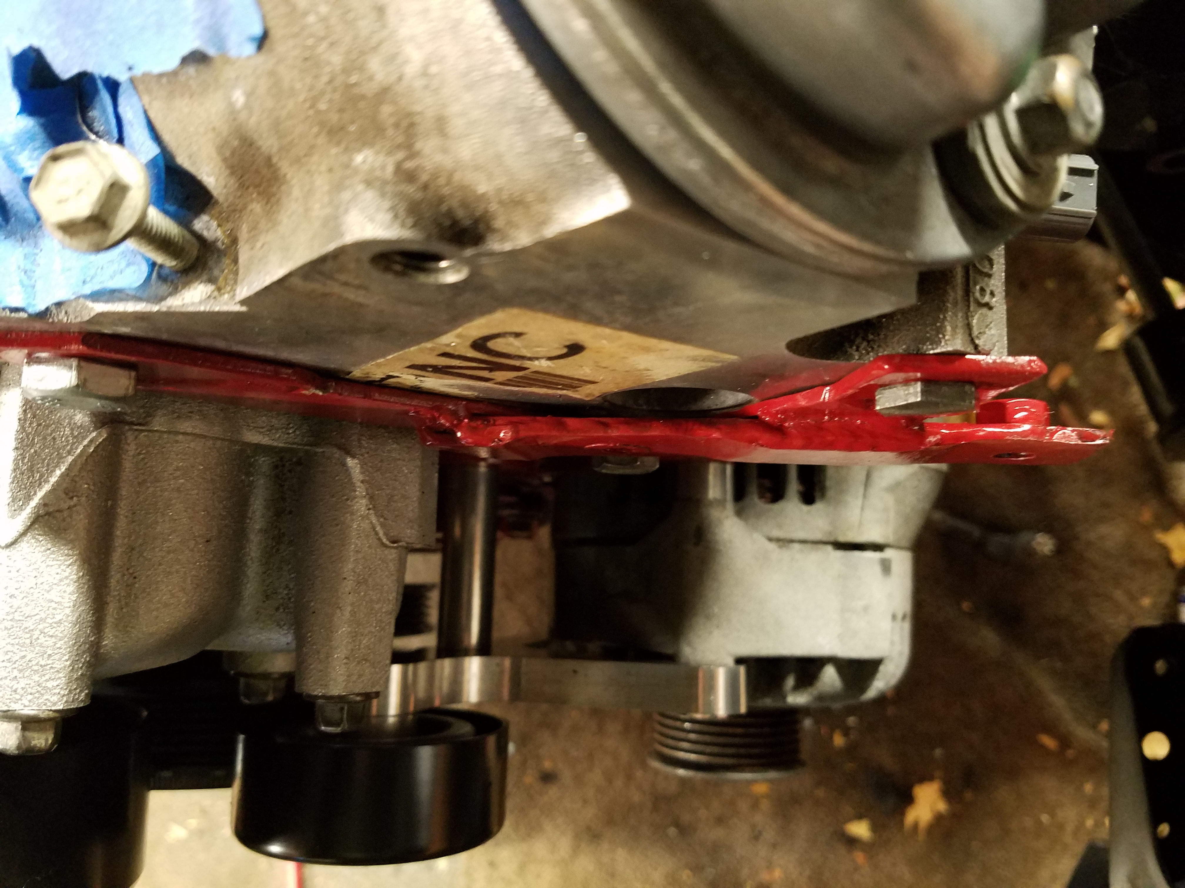
Also made a rear alternator bracket
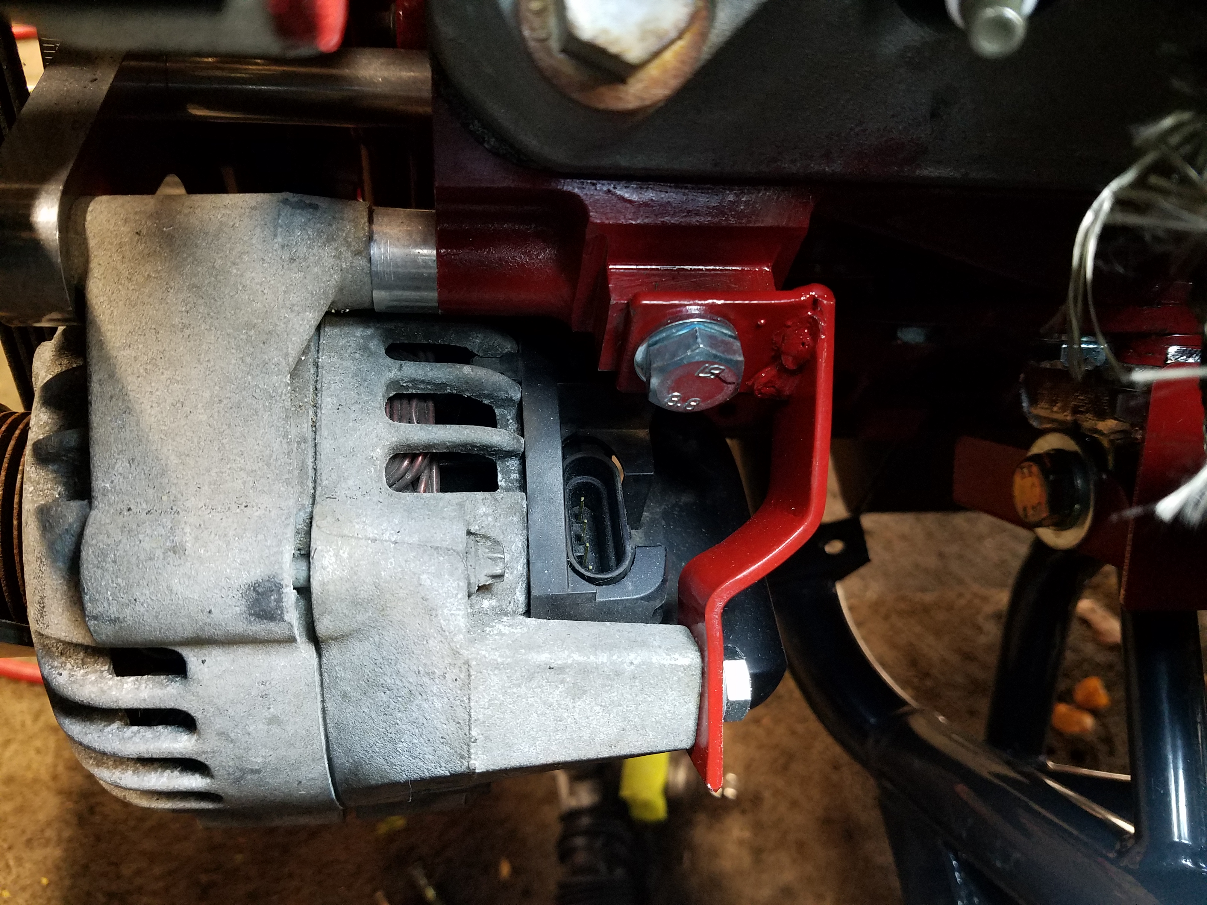
Also made a rear alternator bracket
11-13-2016, 08:15 PM
#69
V8 Miata Enthusiast
Thread Starter
Good eye, I think I forgot the top bushing in that picture during initial fitment. In the last pic of the diff from the side, you can see there are top and bottom bushings. So no, I would not run w/out both of those bushings.
11-16-2016, 03:29 PM
#71
V8 Miata Participant

Just a thought on the rear. If you're using the same bushings on the rear bracket as those used on the front, did you adjust the length of the steel bushing that runs through the rubber bushings? The bushing assembly is designed for the front casting ears that are approximately 1/2" and needs to be shortened if you're not using 1/2" plate.
Looks good, Mike
Looks good, Mike
11-16-2016, 03:42 PM
#72
V8 Miata Enthusiast
Thread Starter
Just a thought on the rear. If you're using the same bushings on the rear bracket as those used on the front, did you adjust the length of the steel bushing that runs through the rubber bushings? The bushing assembly is designed for the front casting ears that are approximately 1/2" and needs to be shortened if you're not using 1/2" plate.
Looks good, Mike
Looks good, Mike
11-16-2016, 03:54 PM
#73
V8 Miata Enthusiast
Thread Starter
Ordered my aluminum driveshaft from Drive Shaft Shop, may be 1-2 weeks for delivery. Once it's fitted I can fine tune the pinion angle and complete the front mounts on the diff.
Realized that I have a V8 Roadsters subframe with the brackets for a NA Miata steering rack, not an NB. If you've compared them before, the passenger side rack mount has a divot for the rubber bushing on the NB, and the bolt holes don't line up. After a bit of cursing I cut off the driver's side mount and will be DIYing a mount but need to spend some time getting it in the right position so the rack is where it should be before welding it in.
Wish this was something I'd checked on while I had the subframe on the ground Needed to walk away from that one for awhile.
Realized that I have a V8 Roadsters subframe with the brackets for a NA Miata steering rack, not an NB. If you've compared them before, the passenger side rack mount has a divot for the rubber bushing on the NB, and the bolt holes don't line up. After a bit of cursing I cut off the driver's side mount and will be DIYing a mount but need to spend some time getting it in the right position so the rack is where it should be before welding it in.
Wish this was something I'd checked on while I had the subframe on the ground
Needed to walk away from that one for awhile.
 11-22-2016, 03:13 PM
#75
V8 Miata Enthusiast
Thread Starter


