5.0L Megasquirt DIYPNP "How-To" - Step-By-Step Instructions
 03-09-2011, 11:34 AM
#1
Administrator
Thread Starter

Join Date: Oct 2009
Posts: 33
Likes: 0
Received 0 Likes
on
0 Posts
The DIYPNP board lets you build your own plug and play engine management systems. The core of the DIYPNP kit is a MicroSquirt module that plugs into an expansion 'mainboard' with on board circuits for many features, including direct coil control, boost control, knock control, and several general purpose inputs and outputs. You assemble this board and jumper it to a 'connector board' which includes a connector to plug into your existing wiring harness. Now you no longer have to solder together awkward adapter harnesses, or hack up a factory ECU case to get a build-it-yourself, plug and play MegaSquirt ECU.
What to buy:
DIYPNP Ford 60 pin EEC-IV Unassembled Kit
http://www.diyautotune.com/catalog/u...Serial Adapter - There are cheaper cables out there, but this is known good on 98, XP, Vista, and Win7. If you buy a different one, make sure the drivers will work for your OS.
That's it! But here are some other recommendations:
MSPNP and DIYPNP IAT Sensor Kit - Aluminum Bung - This Air Intake Temp Sensor allows you to remove the MAF from the intake path. IIRC, the '93 motor has the factory AIT sensor mounted on the intake manifold, so if you have that motor, you can remove the MAF without purchasing a new sensor. The AIT sensor resides within the MAF otherwise. You will have to mount the bung onto your intake plumbing and you can wire it back through the MAF plug/connector (wire is included for this).
Innovate MTX-L powersports gauge - sensor - controller - 3845 - I personally wouldn't install an EMS without a wideband, I like the one linked. Installing a wideband o2 sensor to use with the MS makes fine tuning your fuel tables & enrichments a lot easier, and you get a real picture of your AFR mixture that the narrowband simply cannot output.
What you get in your package:
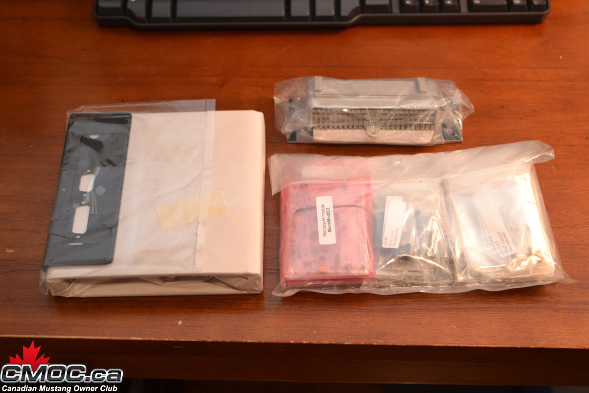
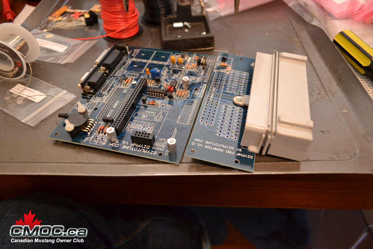
This is the contents of your package. Shown in the case & components you will receive. Each package is clearly marked of its contents.
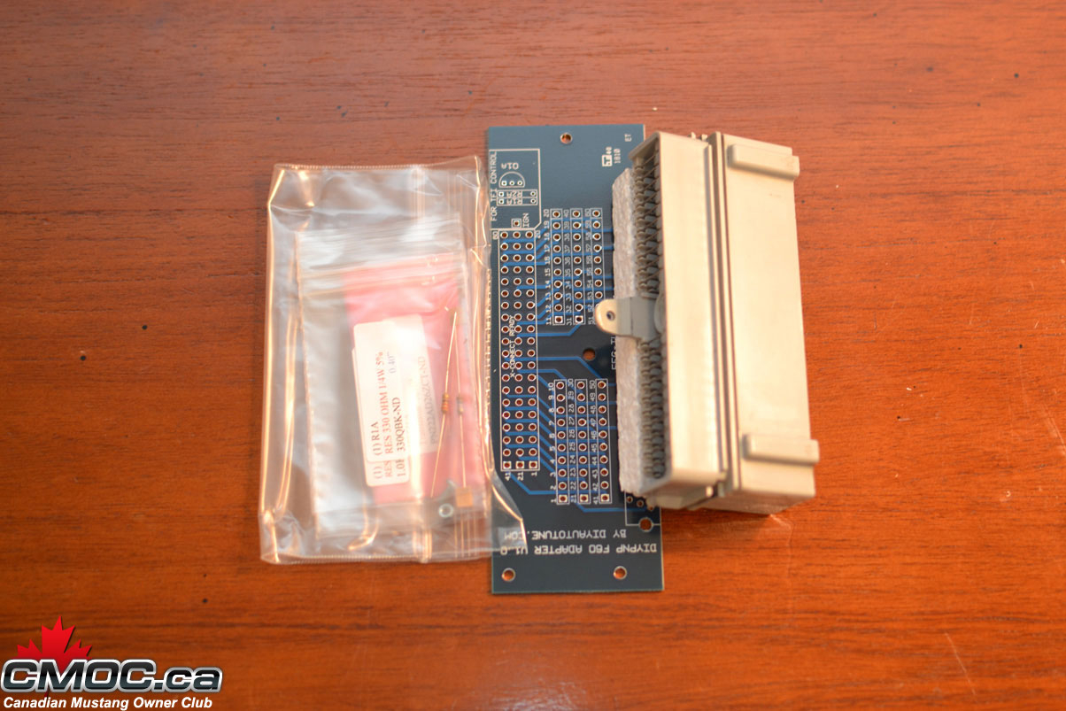

Connector Board - Ford Harness Specific.
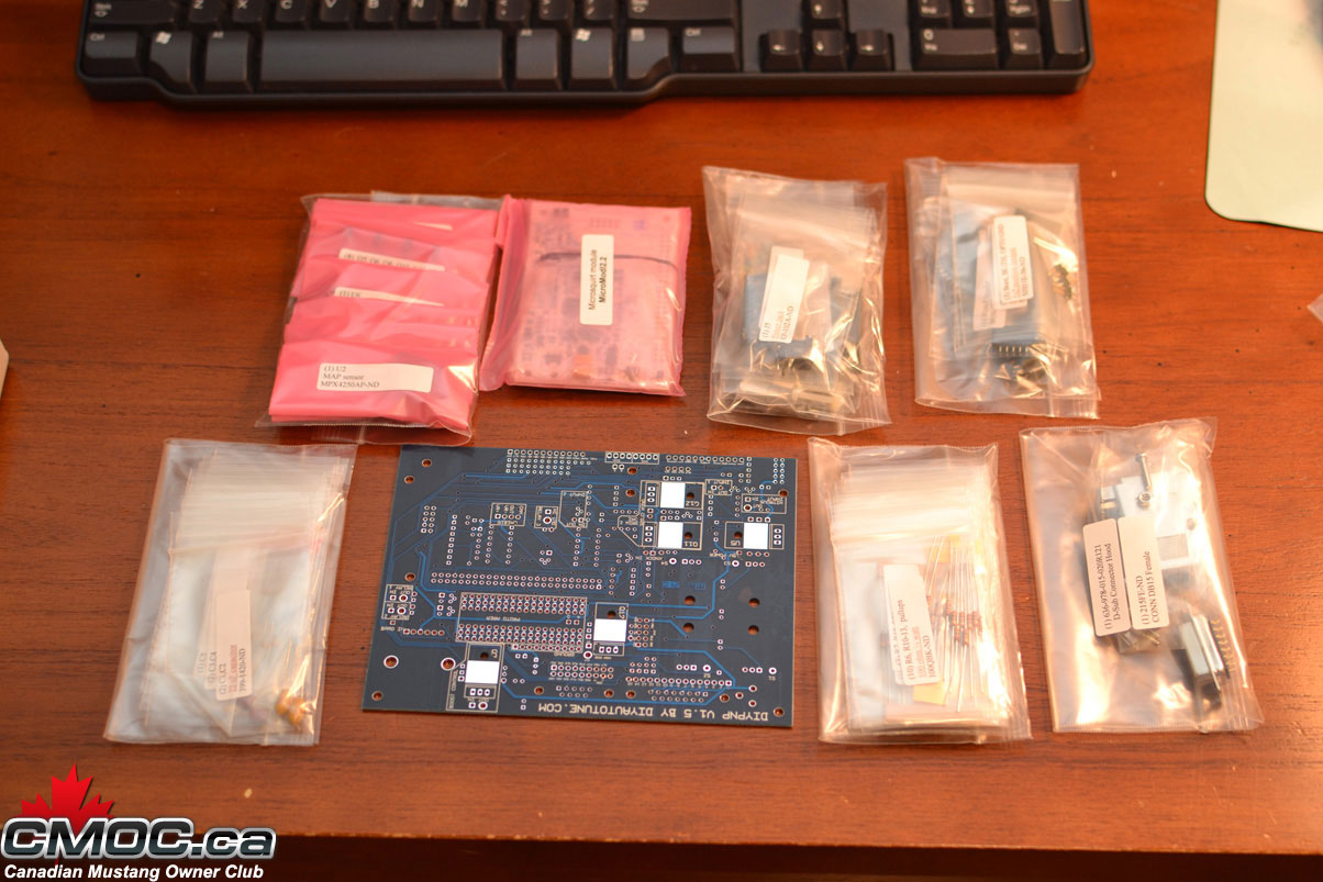
Mainboard and Components.
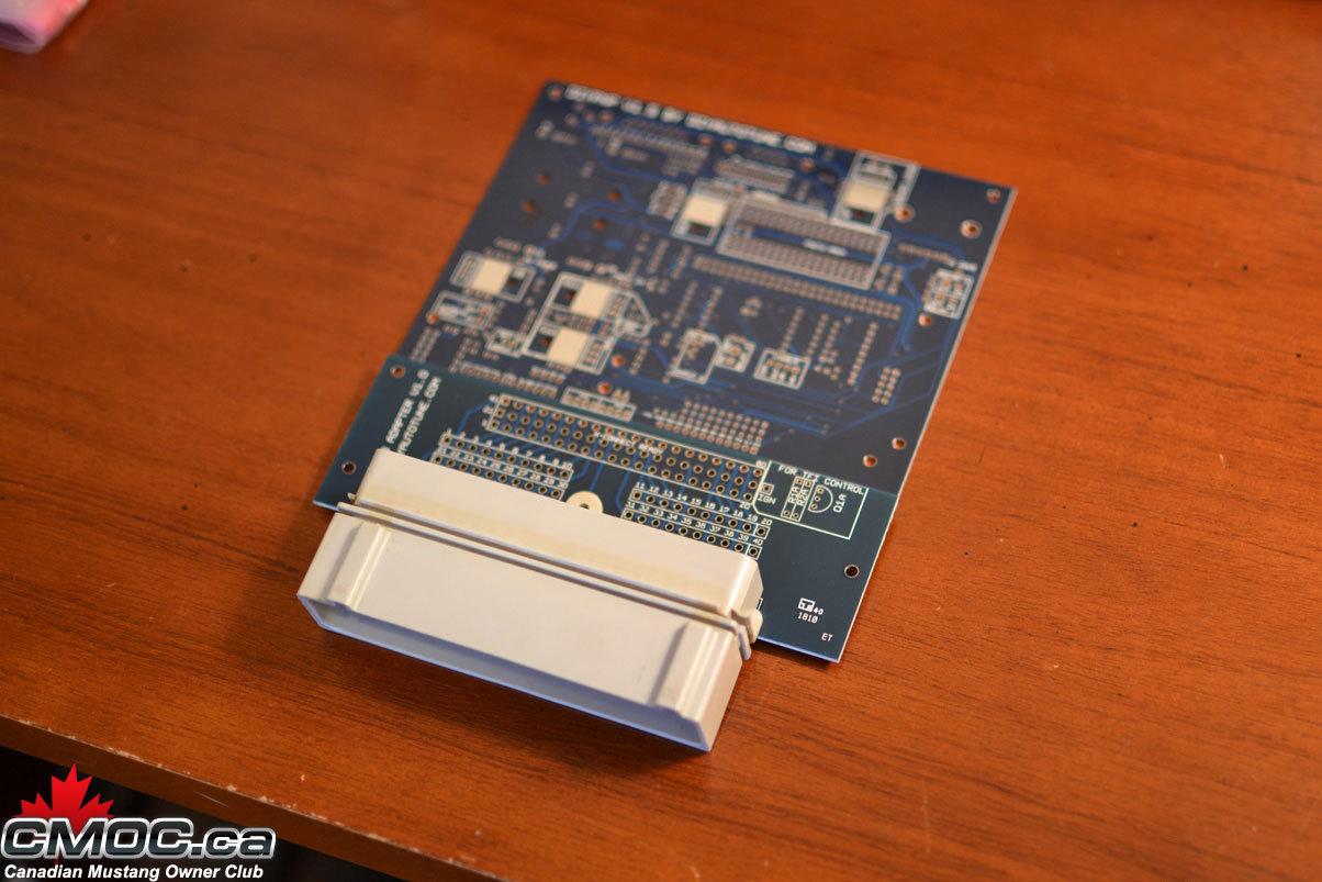
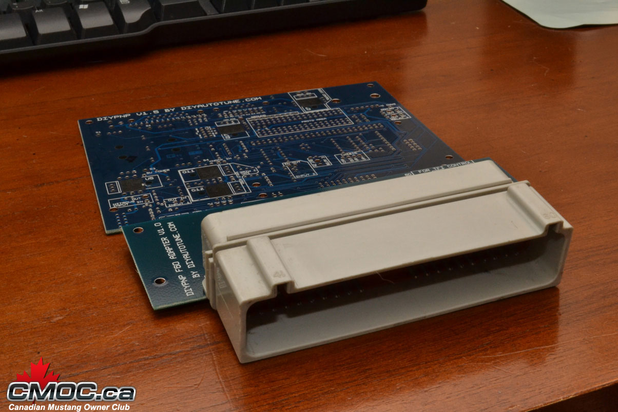
Mainboard and Connector board aligned.
 03-09-2011, 12:01 PM
#2
Administrator
Thread Starter
Join Date: Oct 2009
Posts: 33
Likes: 0
Received 0 Likes
on
0 Posts
Tools Needed to Assemble:
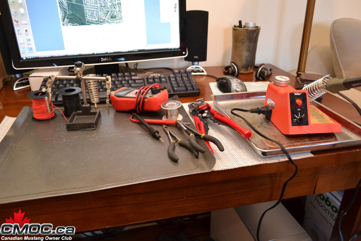
Soldering Iron. Pictured is my trusty $7 40-watt Radio Shack unit plugged into a $30 Weller station to control the temps. Make sure to use a new clean/sharp tip.
Solder. I use 0.030" Resin-Core 60/40.
Wire cutters & Strippers.
Small Pliers. Handy to hold components.
22awg Solid Copper Wire (Red Spool)
22awg Stranded Copper Wire (Black Spool, unused today)
"Helping-Hands". This little guy helps hold the DIYPNP at a good angle when populating components. You can see how I use it below.
All these tools were purchased at my local Radio Shack.
Note: The multi-meter pictured was unused in this assembly, it's just nice to have one handy in case of troubleshooting.
03-09-2011, 12:07 PM
#3
Administrator
Thread Starter
Join Date: Oct 2009
Posts: 33
Likes: 0
Received 0 Likes
on
0 Posts
Main Assembly:
Please review the official assembly documentation here: http://www.diyautotune.com/diypnp/do..._assembly.html
Not everything is required to be populated in order to run the MS on your 5.0L. You can chose to install it all, or just install what I do below.
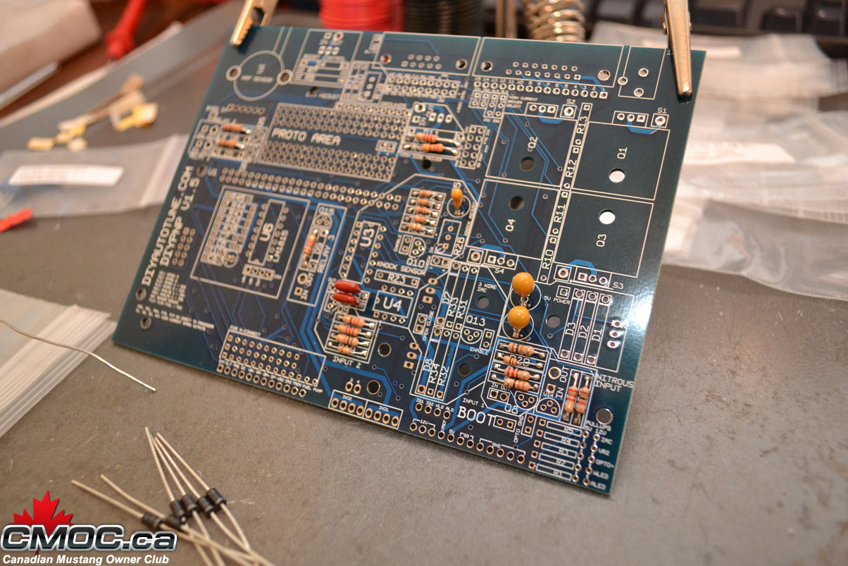
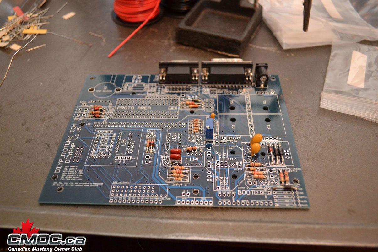
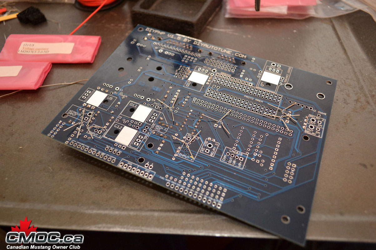
I like to start with the resistors. Setting up the Mainboard on the helping hands, I populate all resistors I chose to install.
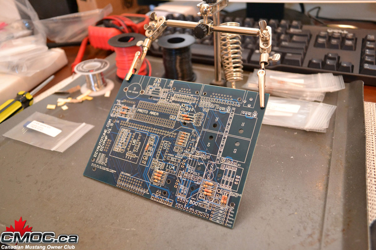
Nothing special about it, simply bend the legs into a "U" and place them into the designated holes.
Once all resistors are populated, I then go through and solder them in place. I do this on the top of the board, holding the solder in my left hand I place the solder against the leg of the resistor right at the hole the component is residing in. Then I bring in the hot iron with my right hand and "melt" the solder into the hole.
Just like this:
Just happening to be doing it on the topside for these. You can bend the leads back so you can flip the board over and do them from the backside, but I find it takes extra time without benefit.
and the result should look like this:
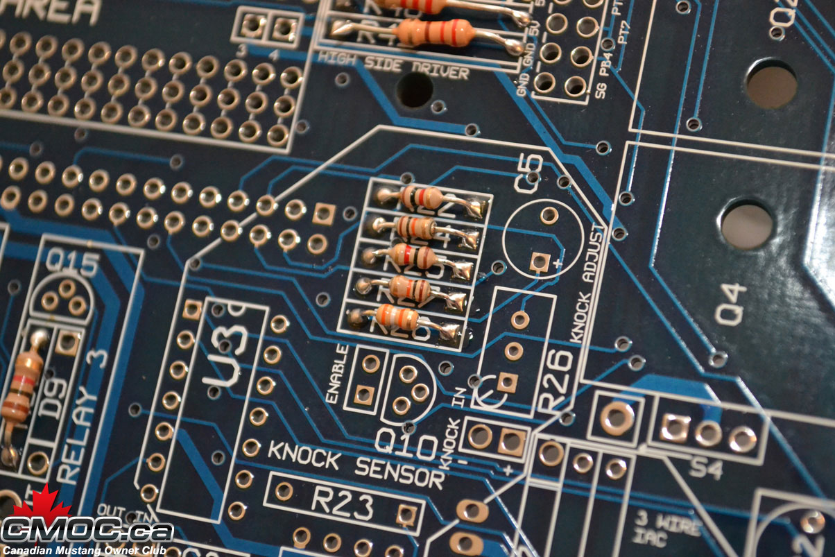
For more information on how to solder components, please review the Google machine.
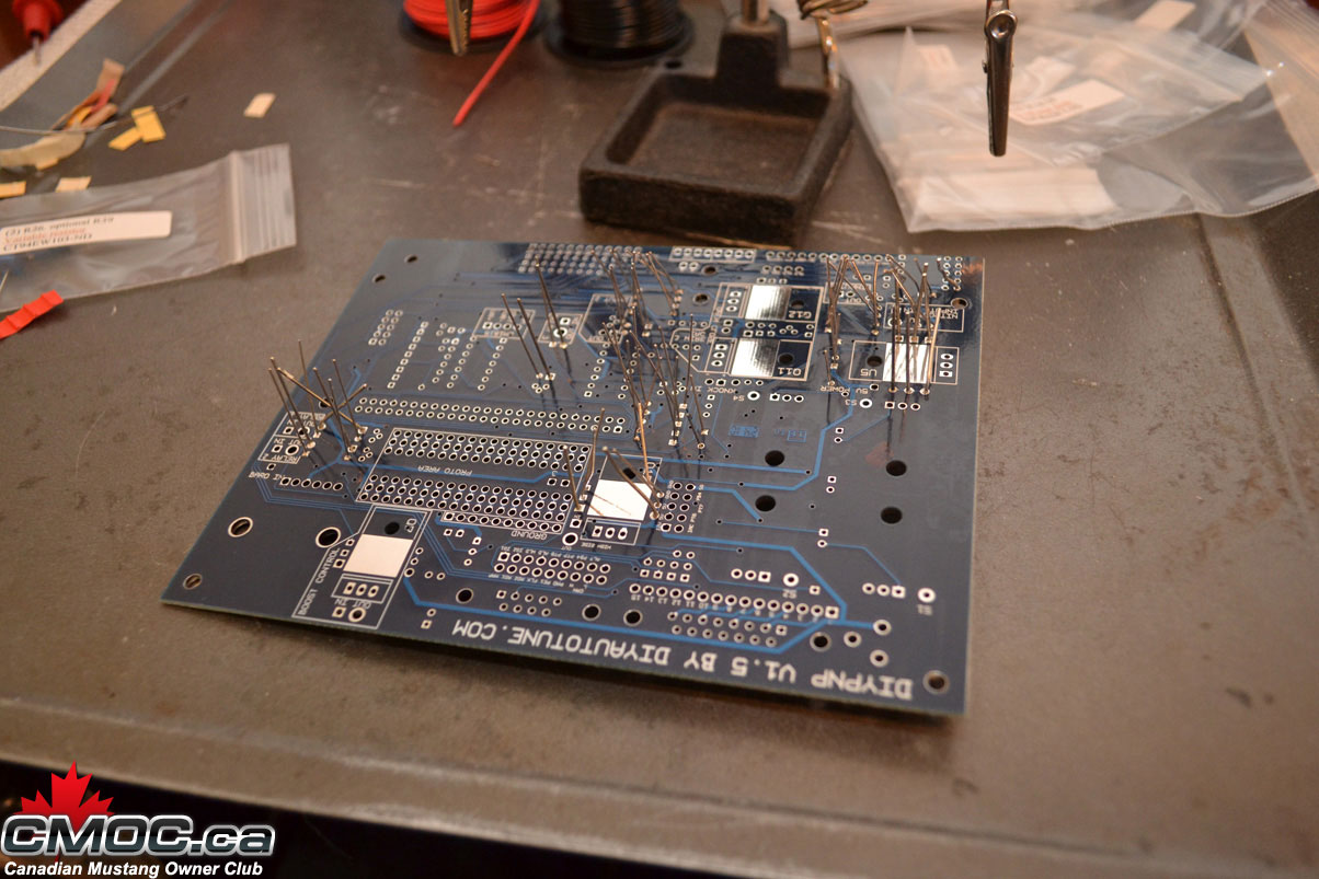
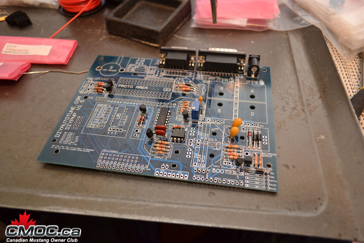
Next I populate the capacitors as shown, please note that three of them are polarity specific. The longer leg goes into the hole stamped with a "+":
then the diodes, banded end is labeled on the board with a thick white line:
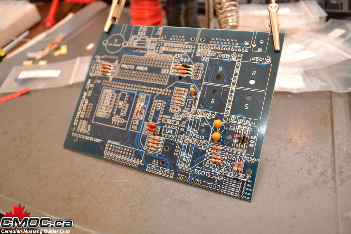
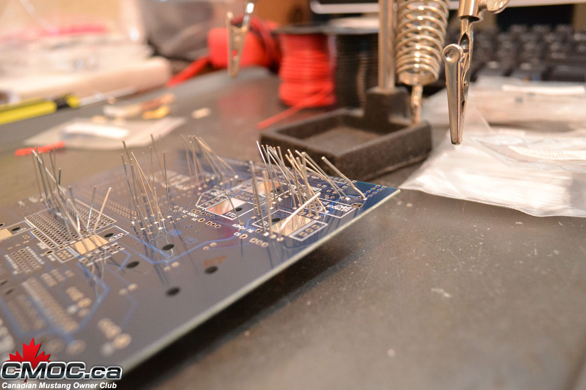
At this point I like to remove the MS from the helping hands and cut off all the legs.
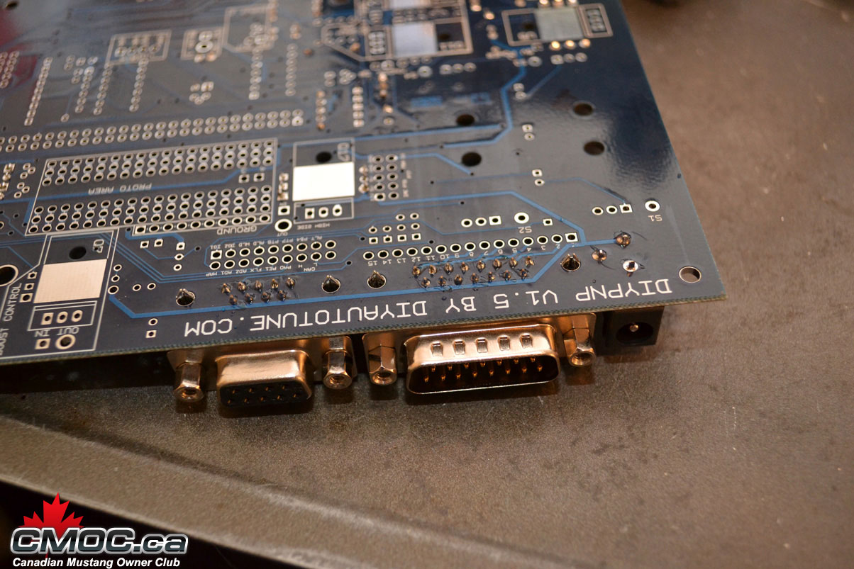
Then you can go ahead and solder in the DB15, DB9, and power input. Place them in and solder from below.
You can also toss now install the pot-resistor for the knock circuit if you're building it:
Please review the official assembly documentation here: http://www.diyautotune.com/diypnp/do..._assembly.html
Not everything is required to be populated in order to run the MS on your 5.0L. You can chose to install it all, or just install what I do below.
I like to start with the resistors. Setting up the Mainboard on the helping hands, I populate all resistors I chose to install.
Nothing special about it, simply bend the legs into a "U" and place them into the designated holes.
Once all resistors are populated, I then go through and solder them in place. I do this on the top of the board, holding the solder in my left hand I place the solder against the leg of the resistor right at the hole the component is residing in. Then I bring in the hot iron with my right hand and "melt" the solder into the hole.
Just like this:
Just happening to be doing it on the topside for these. You can bend the leads back so you can flip the board over and do them from the backside, but I find it takes extra time without benefit.
and the result should look like this:
For more information on how to solder components, please review the Google machine.
Next I populate the capacitors as shown, please note that three of them are polarity specific. The longer leg goes into the hole stamped with a "+":
then the diodes, banded end is labeled on the board with a thick white line:
At this point I like to remove the MS from the helping hands and cut off all the legs.
Then you can go ahead and solder in the DB15, DB9, and power input. Place them in and solder from below.
You can also toss now install the pot-resistor for the knock circuit if you're building it:
03-09-2011, 12:34 PM
#4
Administrator
Thread Starter
Join Date: Oct 2009
Posts: 33
Likes: 0
Received 0 Likes
on
0 Posts
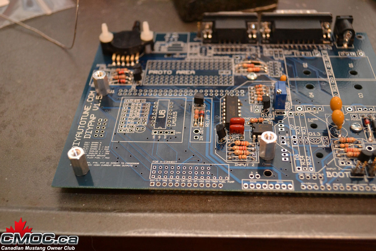
Time to fit the knock sensor drivers and transistors for the input and relay circuits:
You need to squeeze the legs of the drivers inward so they can drop right into the holes, solder one or two legs from above then finish the rest underneath.
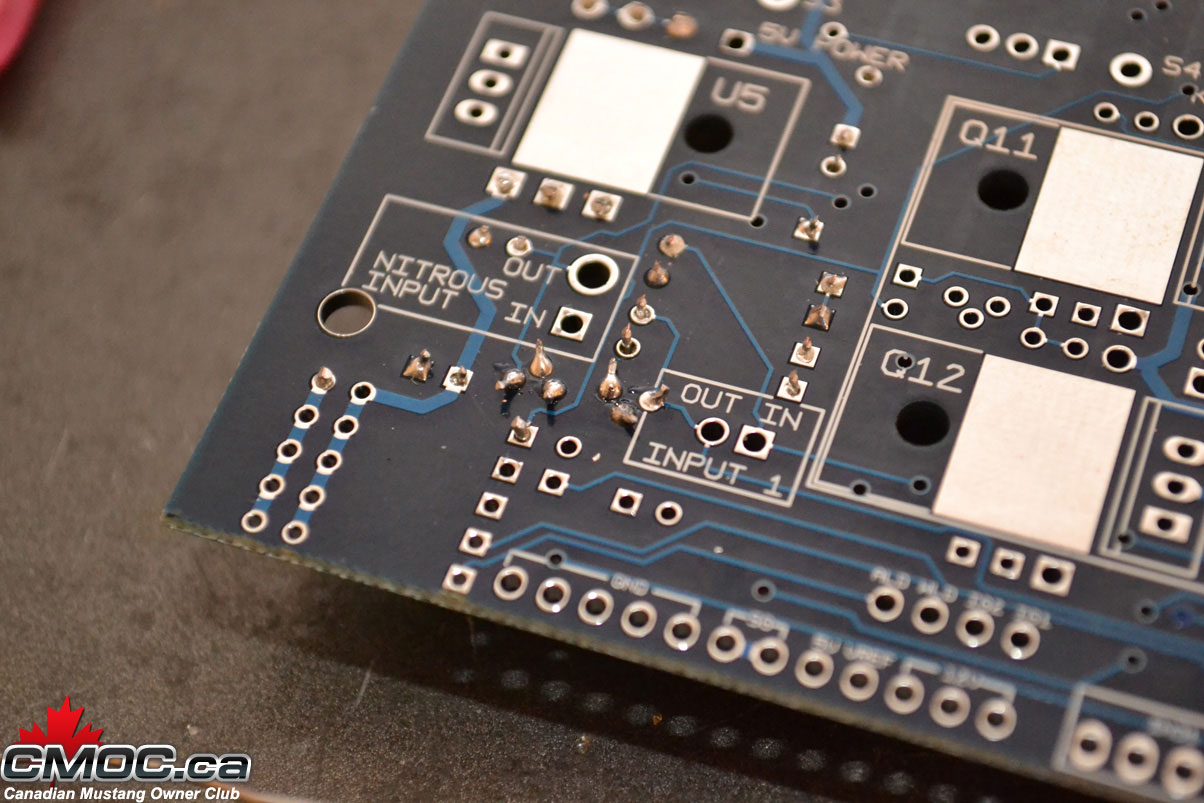
When fitting the transistors, it's good practice to flair the legs on the underside as shown:
Once you start soldering them you'll know why. Be very careful here as it's easy to solder them together. You'll need some de-soldering wire to pull all the solder off.
You should be able to make nice clean, individual joints:
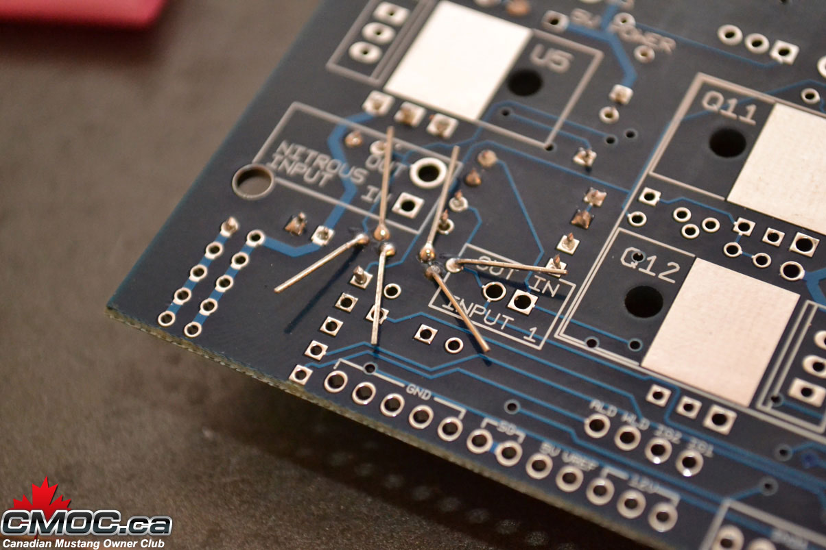
then cut off the excess:
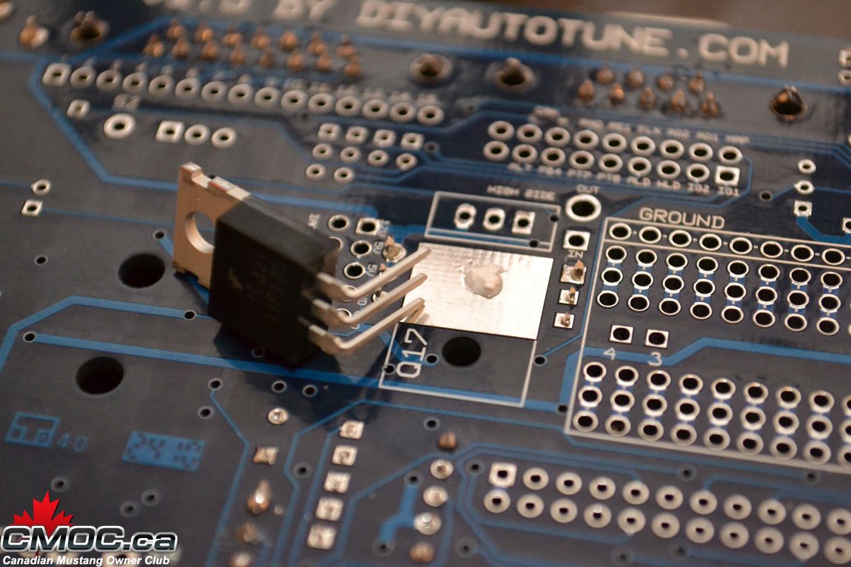
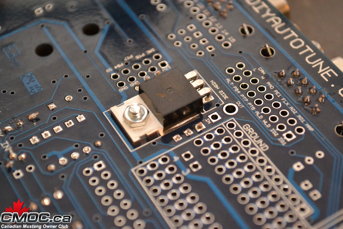
You can now mount the 5v regulator, EBC, and High Side Driver component. Use a small dollop of the heat sink compound on the heatsink area. Here is where the pliers come in handy, Bend the legs so the component can fit right in. Then secure it with the supplied metal screw and nut. Go back and finish soldering once they are all in place.
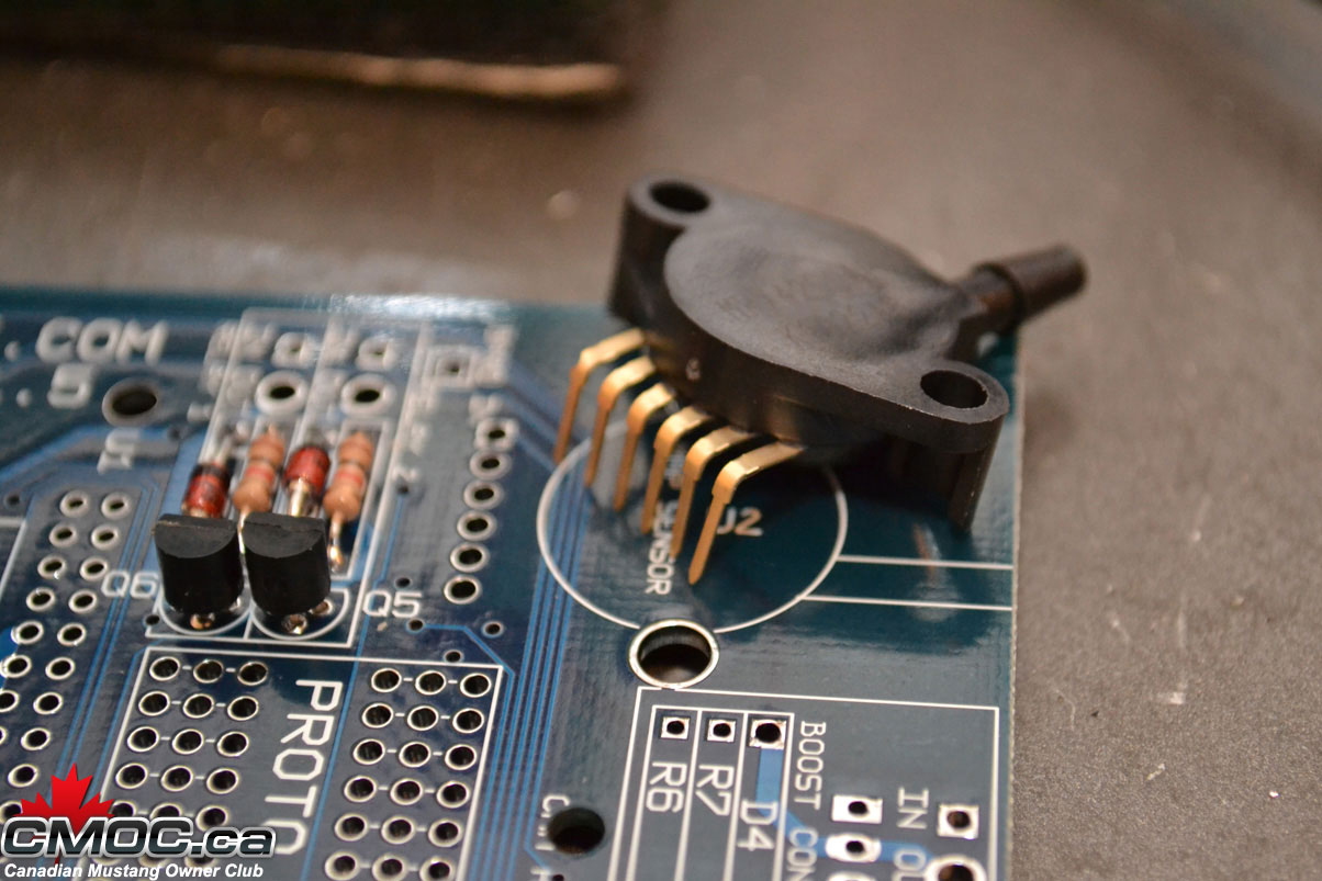
do the same with the MAP sensor, use the two white plastic nuts and bolts:
You need to squeeze the legs of the drivers inward so they can drop right into the holes, solder one or two legs from above then finish the rest underneath.
When fitting the transistors, it's good practice to flair the legs on the underside as shown:
Once you start soldering them you'll know why. Be very careful here as it's easy to solder them together. You'll need some de-soldering wire to pull all the solder off.
You should be able to make nice clean, individual joints:
then cut off the excess:
You can now mount the 5v regulator, EBC, and High Side Driver component. Use a small dollop of the heat sink compound on the heatsink area. Here is where the pliers come in handy, Bend the legs so the component can fit right in. Then secure it with the supplied metal screw and nut. Go back and finish soldering once they are all in place.
do the same with the MAP sensor, use the two white plastic nuts and bolts:
03-09-2011, 12:42 PM
#5
Administrator
Thread Starter
Join Date: Oct 2009
Posts: 33
Likes: 0
Received 0 Likes
on
0 Posts
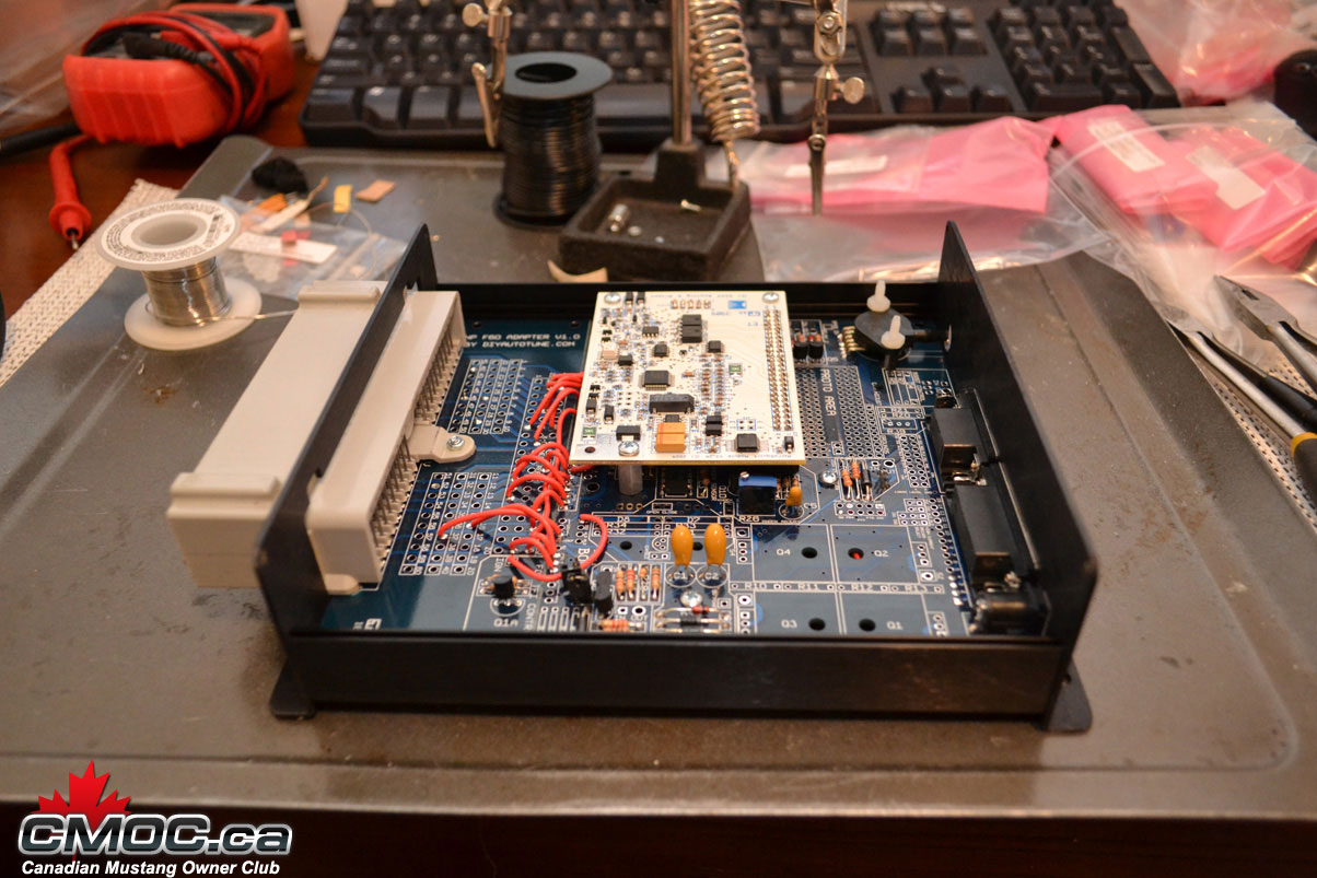
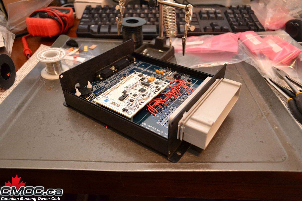
That's it for the components, onward to the CPU.
Install the stand offs with the provided screws as shown:
Then push together the headers and place them as shown:
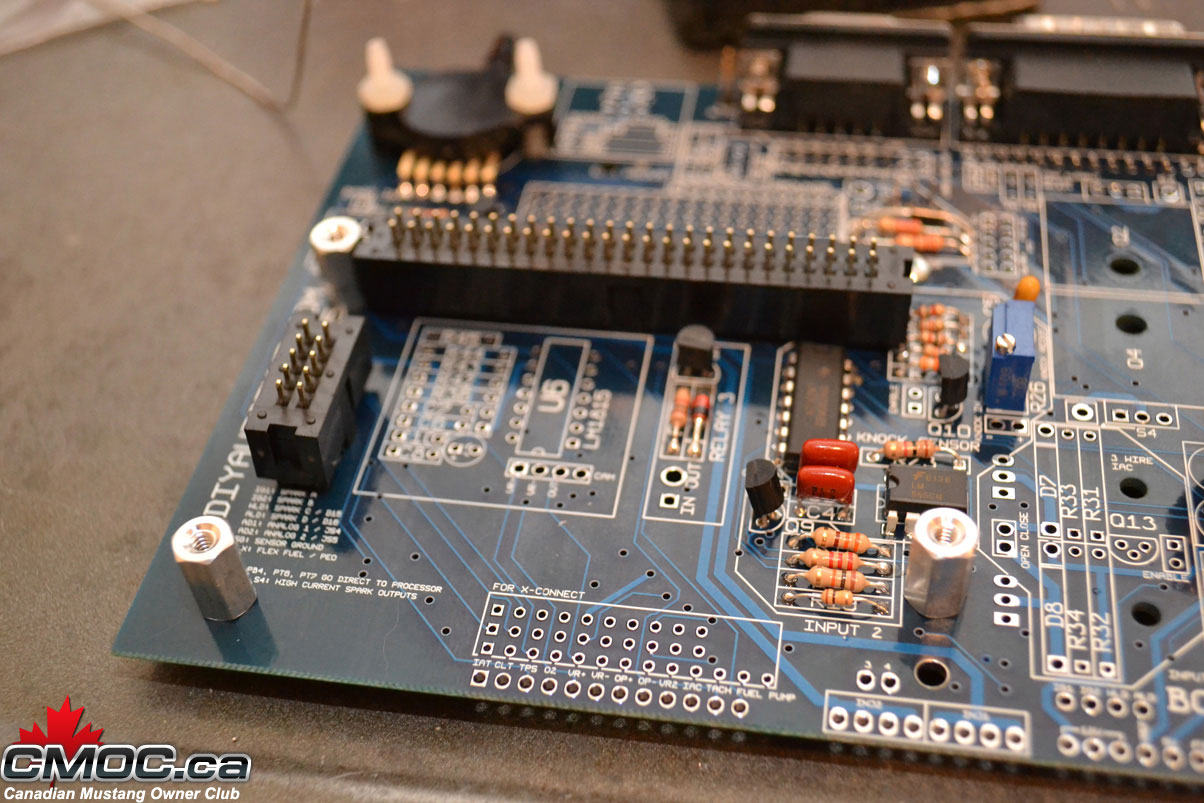
Make sure they sit flush and the tab is pointed inward and the little arrow printed on them is pointing up.
Place the Microsquirt onto, lining up the holes, then screw it in place.
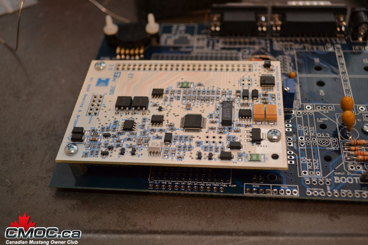
Solder all the joints:
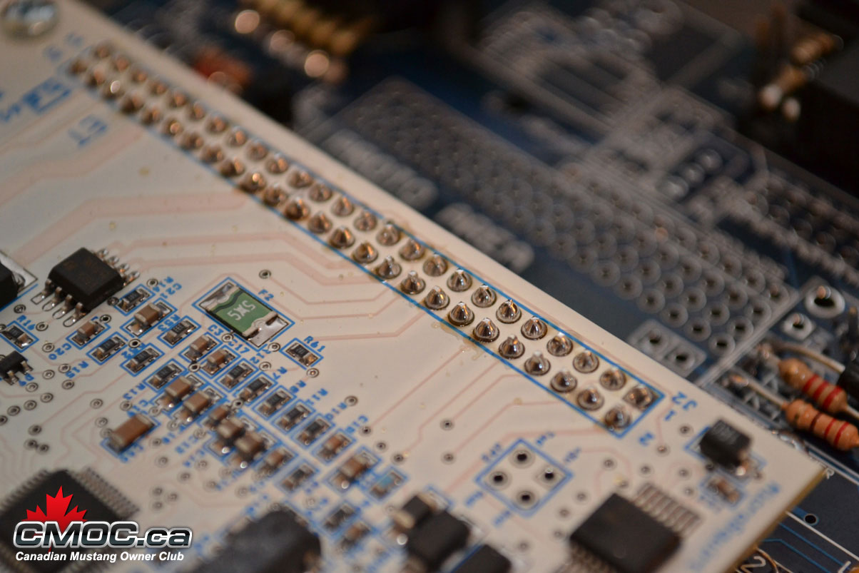
Don't forget the headers on the bottom of the mainboard.
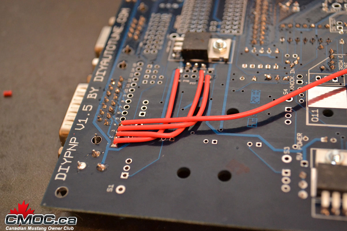
At this point it's time to assemble and connect the connector board. this is the key in how the DIYPNP cleverly is converted into an application specific ECU. Install the connector onto the board, screw it in place carefully, then solder all joints. Populate the small circuit on the board at this point as well.
Once you are ready, line it with the mainboard and we can start connecting the two:
You need to log onto Diyautotune.com's website and follow these directions for the pinouts: http://www.diyautotune.com/diypnp/ap...93-5_0-mt.html
It goes left to right, hole by hole, showing you where to connect the mainboard to the connector board.
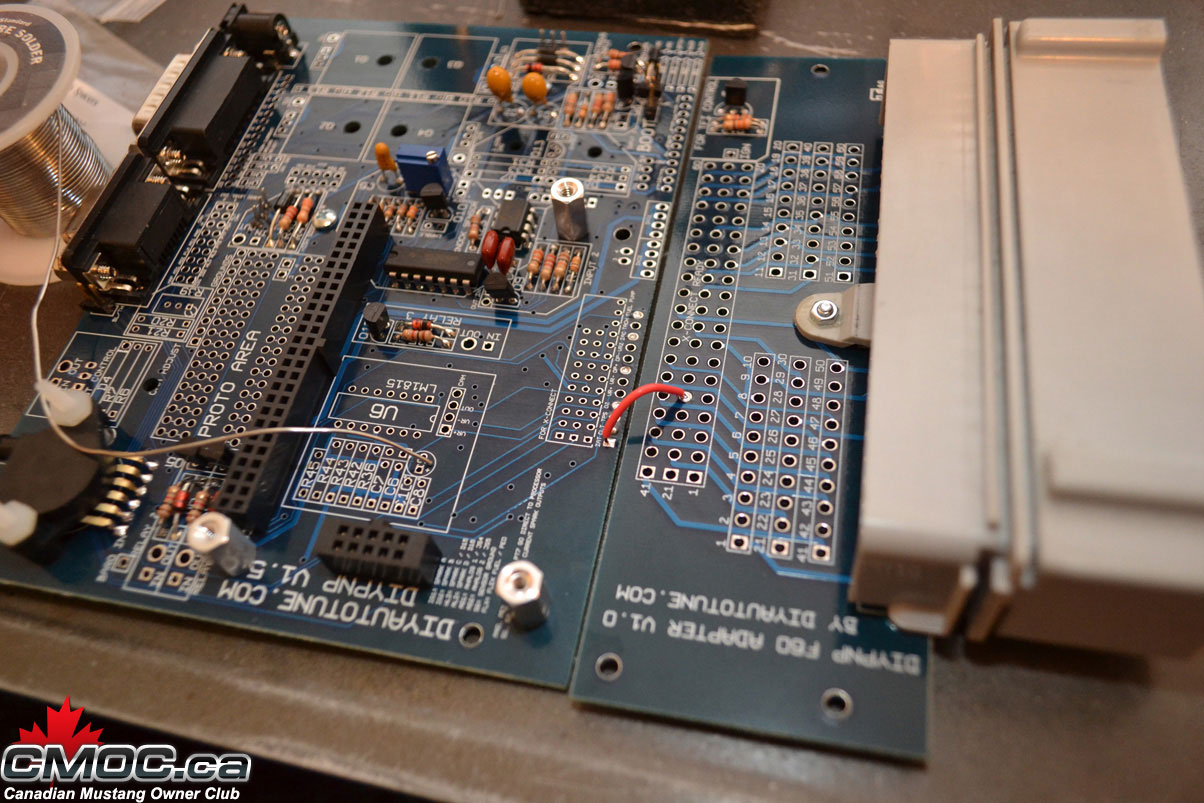
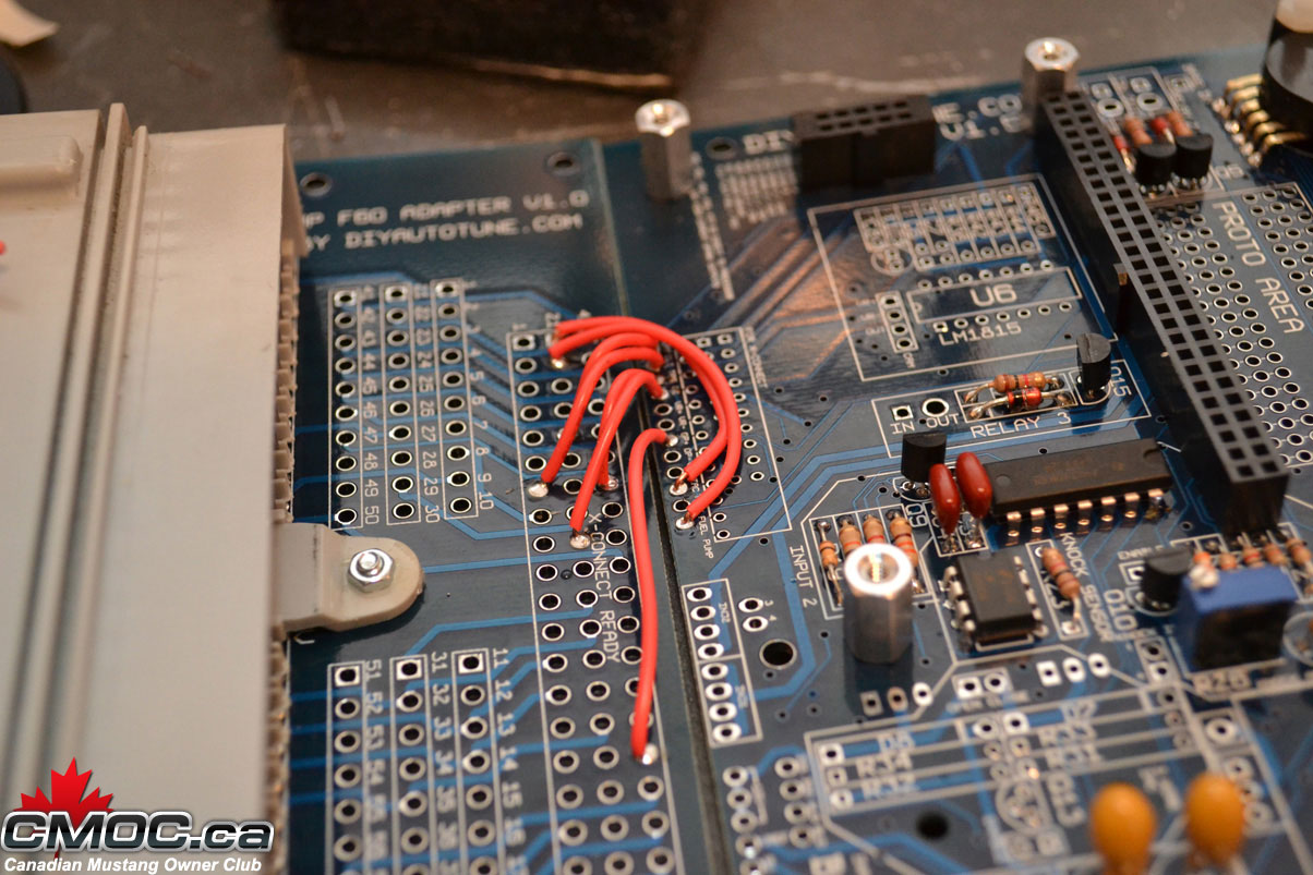
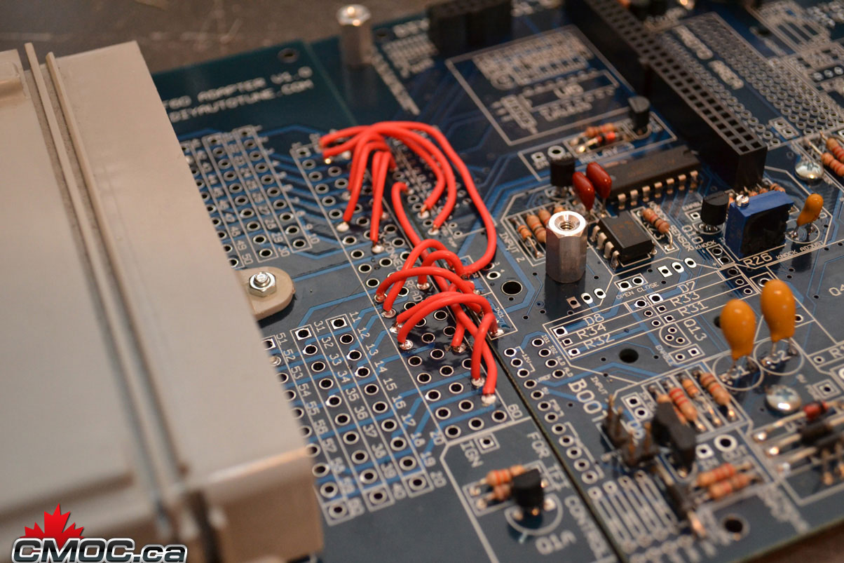
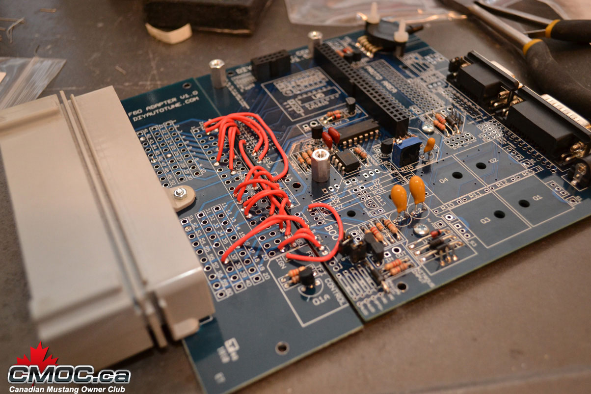
and done.
Install the stand offs with the provided screws as shown:
Then push together the headers and place them as shown:
Make sure they sit flush and the tab is pointed inward and the little arrow printed on them is pointing up.
Place the Microsquirt onto, lining up the holes, then screw it in place.
Solder all the joints:
Don't forget the headers on the bottom of the mainboard.
At this point it's time to assemble and connect the connector board. this is the key in how the DIYPNP cleverly is converted into an application specific ECU. Install the connector onto the board, screw it in place carefully, then solder all joints. Populate the small circuit on the board at this point as well.
Once you are ready, line it with the mainboard and we can start connecting the two:
You need to log onto Diyautotune.com's website and follow these directions for the pinouts: http://www.diyautotune.com/diypnp/ap...93-5_0-mt.html
It goes left to right, hole by hole, showing you where to connect the mainboard to the connector board.
and done.
03-09-2011, 12:51 PM
#6
Administrator
Thread Starter
Join Date: Oct 2009
Posts: 33
Likes: 0
Received 0 Likes
on
0 Posts
At this point you are done with the assembly. You can go further and populate other features of the board. You can use the relay circuits to drive things like fans and switches, the EBC driver, Water Injection, Clutch Input, etc.
If you need help at this point, please contact me and I can help you.
A great thing to do now is populate the inputs/outputs for your DB15 connector. This is a blank canvas for simple wiring to and from your MS.
I like to populate mine like this:
#1 - 12v
#2 - GND
#3 - SG
#4 - O2
This gives me a perfect place to wire up my wideband o2 sensor. I can use the power, ground, sensor ground to power the unit, and then the o2 input on #4 to send the signal into the MS.
Reinstall the CPU, and start to assemble the case.
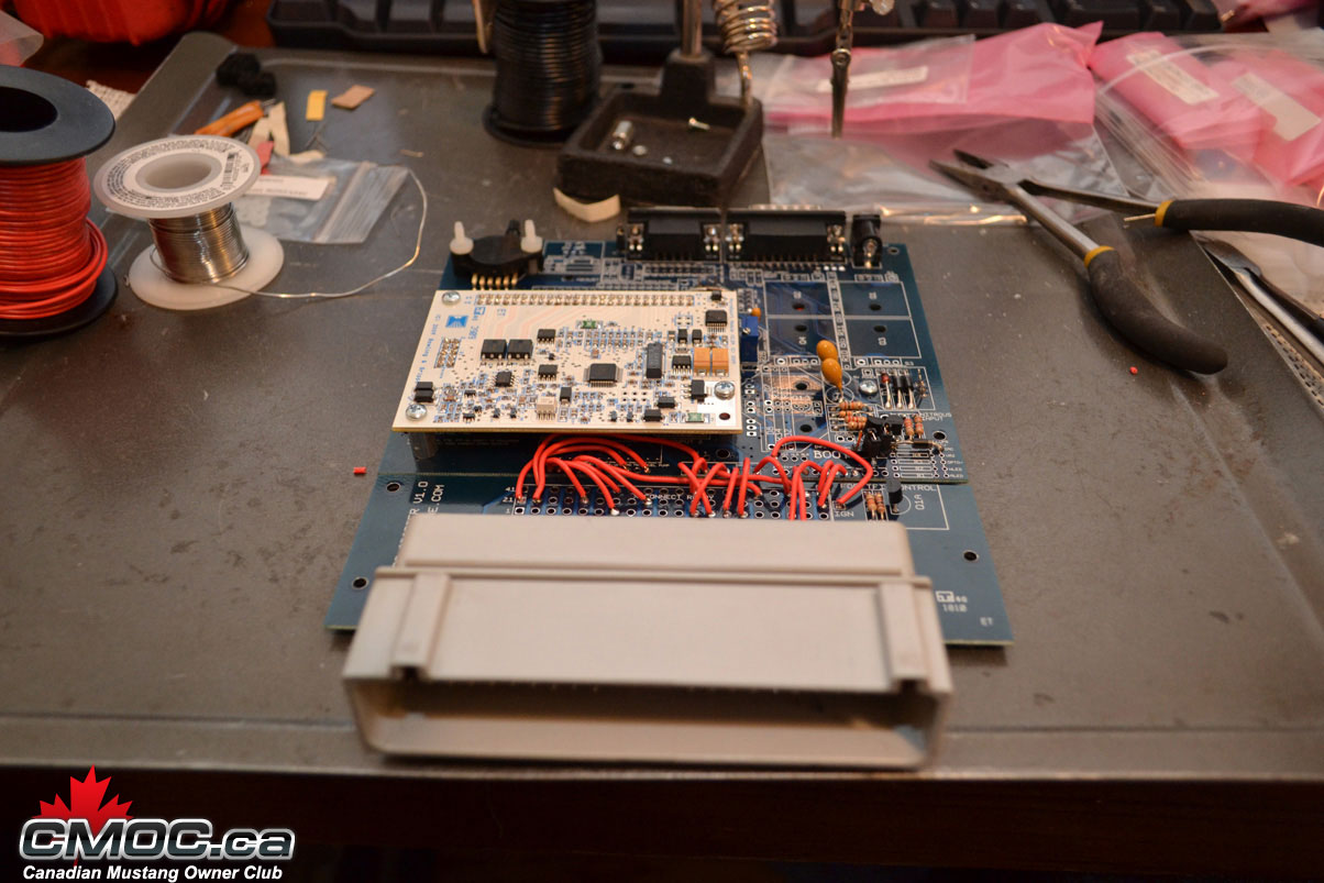
Slide it into the 2nd slot and attach the end plate with the nuts on the DB9 an dDB15:
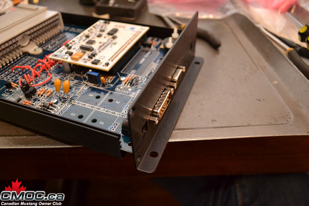
Screw it in place and then slide the second end-plate over the connector and screw it in place as well.
all done:
From start to finish at this point, even taking pictures it took me just over an hour. Time to start loading software, a base tune, and getting it installed.
If you need help at this point, please contact me and I can help you.
A great thing to do now is populate the inputs/outputs for your DB15 connector. This is a blank canvas for simple wiring to and from your MS.
I like to populate mine like this:
#1 - 12v
#2 - GND
#3 - SG
#4 - O2
This gives me a perfect place to wire up my wideband o2 sensor. I can use the power, ground, sensor ground to power the unit, and then the o2 input on #4 to send the signal into the MS.
Reinstall the CPU, and start to assemble the case.
Slide it into the 2nd slot and attach the end plate with the nuts on the DB9 an dDB15:
Screw it in place and then slide the second end-plate over the connector and screw it in place as well.
all done:
From start to finish at this point, even taking pictures it took me just over an hour. Time to start loading software, a base tune, and getting it installed.
03-09-2011, 01:16 PM
#7
Administrator
Thread Starter
Join Date: Oct 2009
Posts: 33
Likes: 0
Received 0 Likes
on
0 Posts
Loading Firmware:
Go here and download the firmware: http://msextra.com/doc/ms2extra/file....0_release.zip
unzip it somewhere you can find it again.
Unplug your coil from the car if you're not using a power supply. This is not the same as unplugging the spark plug wires, you need to unplug the coil.
On the bottom right hand corner of the main board, you should see two holes labeled BOOT. Make sure the boot jumper is jumping the pins.
Open the folder and double click download-MS2-Firmware.bat
When prompted press (2) for microsquirt. Then your comm port #. Hit (1) next. Now hit (Y). It will instruct you to power on the MS with the boot jump in place. so follow the instructions.
then it will instruct you to turn off the unit, remove the jumper, and turn back on the power.
Once you follow these steps it will take about 5 minutes to load the firmware. it will prompt once done.
Software Setup:
You need to start with a fresh install of Tuner Studio.
https://www.efianalytics.com/TunerStudio/download
This link provides you with all the latest TS verison.
Run the installer and open Tuner Studio, this is the program you’ll be using. If it asks to update, please do so now. Do not change the default install directory.
Now download this file: http://msextra.com/doc/ms2extra/file....0_release.zip
And extract it into your “TunerStudio Projects Folder” under My Docs.
Open Tuner Studio and go to the file menu, and select Project. Under the pull up menu in Projects, you will be given a few choices related to the project. Since you want to set up for your car, the first thing you want to do is select NEW PROJECT.
This screen should open up:
{IMAGE}
Name the project something that you can easily identify, and make it specific. For example, “My Project” you can name it whatever you like, it doesn’t really matter.
Make sure under “Project Directory,” to save it to the Tuner Studio Projects Folder, which should default in your My Documents folder. Otherwise on some Vista and 7 machines, you may have issues saving files.
Next, you need to select the firmware you will be using.
You should be able, to simply click the down arrow and find “MS2Extra Rel 3.1.0”. If that is not an option, check other, then the "…", and navigate to the Megatune directory and find the folder for “ms2extra_3.1.0_release” that you downloaded, then select the .ini file within and continue on.
{IMAGE}
On the next page, choose your settings for however you need to set up your car. Select Wideband or Narrowband depending on the o2 sensor you'll be using, and then scroll down and select Micosquirt_Module to ACTIVE.
{IMAGE}
On the next page, please select the com port of your usb-serial cable. MS-II baud rate is 115200.
Before you test your connection and power up the MS for the first time and you are powering it from your car and not the stim power adapater, make sure to unplug your coils.
Now, test the connection with your MS [attached and ignition turned to] ON.
{IMAGE}
Configuring your Sensors:
Once you connect to your MS and setup your project you need to calibrate a few of the inputs: AFR, TPS, Coolant, Air Temp.
Under Tools > Calibrate TPS
Now click 'Tools > Calibrate Thermistor Tables'. Make sure 'Coolant Temperature Sensor' is selected at the top.
Use the following table with a bias resistor setting of 2490 ohms:
Temperature F / C Resistance In Ohms
50 / 10 58750
176 / 80 3840
230 / 110 1550
Click "write to controller"
Now you'll do the same for the IAT. Select 'Intake Temperature Sensor' at the top in the drop down box.
If you are using the MAF from the 5.0L and thus the stock AIT sensor,use the following table:
Temperature F / C Resistance In Ohms
50 / 10 58750
176 / 80 3840
230 / 110 1550
For the GM IAT sensor, use the following table with a bias resistor setting of 2490 ohms:
Temperature �F Resistance In Ohms
48 7000
87 1930
146 560
Enter these values, and click ''.
Now click Close to Exit.
Finally, you should calibrate your O2 Sensor to the ECU.
To do this, click 'Tools > Calibrate AFR Table'.
At this point you can load the basemap. Download the basemap from Diyautotune here: http://www.diyautotune.com/diypnp/ap...893-5_0-mt.zip
Extract it anywhere and go to File > Open Tune. Select the tune file out of the folder you just downloaded and let it write to the controller.
TO BE CONTINUED.
Go here and download the firmware: http://msextra.com/doc/ms2extra/file....0_release.zip
unzip it somewhere you can find it again.
Unplug your coil from the car if you're not using a power supply. This is not the same as unplugging the spark plug wires, you need to unplug the coil.
On the bottom right hand corner of the main board, you should see two holes labeled BOOT. Make sure the boot jumper is jumping the pins.
Open the folder and double click download-MS2-Firmware.bat
When prompted press (2) for microsquirt. Then your comm port #. Hit (1) next. Now hit (Y). It will instruct you to power on the MS with the boot jump in place. so follow the instructions.
then it will instruct you to turn off the unit, remove the jumper, and turn back on the power.
Once you follow these steps it will take about 5 minutes to load the firmware. it will prompt once done.
Software Setup:
You need to start with a fresh install of Tuner Studio.
https://www.efianalytics.com/TunerStudio/download
This link provides you with all the latest TS verison.
Run the installer and open Tuner Studio, this is the program you’ll be using. If it asks to update, please do so now. Do not change the default install directory.
Now download this file: http://msextra.com/doc/ms2extra/file....0_release.zip
And extract it into your “TunerStudio Projects Folder” under My Docs.
Open Tuner Studio and go to the file menu, and select Project. Under the pull up menu in Projects, you will be given a few choices related to the project. Since you want to set up for your car, the first thing you want to do is select NEW PROJECT.
This screen should open up:
{IMAGE}
Name the project something that you can easily identify, and make it specific. For example, “My Project” you can name it whatever you like, it doesn’t really matter.
Make sure under “Project Directory,” to save it to the Tuner Studio Projects Folder, which should default in your My Documents folder. Otherwise on some Vista and 7 machines, you may have issues saving files.
Next, you need to select the firmware you will be using.
You should be able, to simply click the down arrow and find “MS2Extra Rel 3.1.0”. If that is not an option, check other, then the "…", and navigate to the Megatune directory and find the folder for “ms2extra_3.1.0_release” that you downloaded, then select the .ini file within and continue on.
{IMAGE}
On the next page, choose your settings for however you need to set up your car. Select Wideband or Narrowband depending on the o2 sensor you'll be using, and then scroll down and select Micosquirt_Module to ACTIVE.
{IMAGE}
On the next page, please select the com port of your usb-serial cable. MS-II baud rate is 115200.
Before you test your connection and power up the MS for the first time and you are powering it from your car and not the stim power adapater, make sure to unplug your coils.
Now, test the connection with your MS [attached and ignition turned to] ON.
{IMAGE}
Configuring your Sensors:
Once you connect to your MS and setup your project you need to calibrate a few of the inputs: AFR, TPS, Coolant, Air Temp.
Under Tools > Calibrate TPS
- Key in the on position, car should not be running.
- With your foot OFF the throttle, click 'GET CURRENT' for the Closed Throttle ADC Count
- Floor it and hold it there. Click 'GET CURRENT' for the Full Throttle ADC Count
- Click Close
Now click 'Tools > Calibrate Thermistor Tables'. Make sure 'Coolant Temperature Sensor' is selected at the top.
Use the following table with a bias resistor setting of 2490 ohms:
Temperature F / C Resistance In Ohms
50 / 10 58750
176 / 80 3840
230 / 110 1550
Click "write to controller"
Now you'll do the same for the IAT. Select 'Intake Temperature Sensor' at the top in the drop down box.
If you are using the MAF from the 5.0L and thus the stock AIT sensor,use the following table:
Temperature F / C Resistance In Ohms
50 / 10 58750
176 / 80 3840
230 / 110 1550
For the GM IAT sensor, use the following table with a bias resistor setting of 2490 ohms:
Temperature �F Resistance In Ohms
48 7000
87 1930
146 560
Enter these values, and click ''.
Now click Close to Exit.
Finally, you should calibrate your O2 Sensor to the ECU.
To do this, click 'Tools > Calibrate AFR Table'.
- Choose your O2 Sensor from the list. Choose Narrowband for the stock O2 Sensor. Or select your wideband and the proper configuration of said wideband from the drop-down list.
- Click 'Write to Controller'.
- Once finished writing, click 'Close'.
At this point you can load the basemap. Download the basemap from Diyautotune here: http://www.diyautotune.com/diypnp/ap...893-5_0-mt.zip
Extract it anywhere and go to File > Open Tune. Select the tune file out of the folder you just downloaded and let it write to the controller.
TO BE CONTINUED.
03-09-2011, 01:17 PM
#8
Administrator
Thread Starter
Join Date: Oct 2009
Posts: 33
Likes: 0
Received 0 Likes
on
0 Posts
Configuring your tune:
Once you start the car, the first thing you have to do it match the ignition timing! MS has no idea what your timing is so driving on your new ECU without doing this is potential for serious failure.
Start and idle the car and allow it to warm-up and stabilize.
Open up Basic Setup > More Ignition Options.
To adjust the timing you adjust the trigger angle, that�s it. No more rotating the distributor, this is same concept.
Change the �Fixed Advance� from �Use table� to �Fixed Timing�, Then make sure �Timing for Fixed Advanced� is set to '20.0'. By doing this, you�re telling your Megasquirt to hold the ignition timing at 20� no matter what. This is essentially what you are doing when you would jump GND and TEN in the past. Since MS has control of your timing now, this is how you can lock the timing.
{IMAGE}
Use your timing light and verify the timing is correct. The timing mark should land on 20�.
If not, we need to change the Trigger Angle.
Go to Tools > Trigger Wizard
Click + or � until your timing mark lines up to 20�. Once your timing light indicates 20� you have now synced the distributor position and the MS. Burn that value.
Reopen �More Ignition Options�
Let�s make sure your spark hardware latency is configured. You can see by default it�s set to 0. The timing latency is code to help prevent the timing from dropping off in higher RPMs. You can verify by locking ignition timing 20�, which it should still be, and then slowly running the engine from idle to 6,000 RPM while observing with a timing gun. If the spark tends to retard as RPM goes up, you need to add latency correction until it stays at 20�.
Once you are happy with your timing and latency values, change the �Fixed Angle� back to �Use Map�.If you fail to do this, your timing will remain at 20� regardless of RPM or load, this will overheat your motor fast and run very sluggish.
If done correctly and you go back out with a timing light you should see you�re probably idling in the 15-18� range, whatever the basemap puts you at for your particular load/rpm cell.
That�s it! You�re now ready to tune this baby up. You changed your timing back to �use map� right?
Tuning Fuel:
Your spark table, by default, is a good conservative table; So focus on fuel.
Go to Basic Settings > VE Table 1
That�s the fuel map. When idling you can see where it's reading the table from. When you drive you can see your AFR gauge react to whatever situation your table is in; adjust as needed. It should be close...you might have to increase the table by 5-10 point throughout to idle good.
If you highlight cell you can plug numbers in on the top. If you want to increase by 5 points, highlight the cells you want, hit the plus sign, then enter in a value.
Let's setup your AFR targets now.
Turn EGO Control on. Step size 1% will allow the ECU to make on the fly adjustments based of your AFR reading to try to match your AFR targets table. You can change the speed it reacts (events per step), how much it can change your table numbers (Auth) and other parameters.
Then go to Basic Settings > AFR table 1 � Setup your AFR targets how you�d like, these are my defaults.
These are the AFR targets you�re telling the MS you want to hit, it will compare the actualy AFR readings from your o2, and compare them to this table and make on-the-fly adjustments to try to match your AFR Targets Table.
03-09-2011, 01:20 PM
#9
Administrator
Thread Starter
Join Date: Oct 2009
Posts: 33
Likes: 0
Received 0 Likes
on
0 Posts
Figured I'd post this now, I gotta go back in and discuss loading firmware and getting started, but I've had a few people ask me about this so I wanted to get it out there.
Like I mention above, the assembly itself took me about an hour. Software will take you another 30 minutes or so, most of the time is waiting for the firmware to flash.
Installation is easy and straight forward, but with the supplied base maps and this writeup, you should easily be running with MS as your EMS over the weekend, with time to spare and watch the game on Sunday.
03-10-2011, 01:12 PM
#10
Administrator

Join Date: Oct 2009
Posts: 253
Likes: 0
Received 0 Likes
on
0 Posts
Built for the project stang!
LOL
Ill have to lay down some dyno numbers then install
Amazing write up!
LOL
Ill have to lay down some dyno numbers then install
Amazing write up!

 06-09-2011, 08:09 PM
#15
V8 Miata Fan

Join Date: Nov 2010
Location: Saint Louis, MO
Posts: 67
Likes: 0
Received 0 Likes
on
0 Posts
What about this product it is already assembled?
Am I missing something here why would we wire one up if they already sell it pre-made?
http://www.diyautotune.com/catalog/m...ang-p-418.html
Am I missing something here why would we wire one up if they already sell it pre-made?
http://www.diyautotune.com/catalog/m...ang-p-418.html
06-10-2011, 01:42 PM
#16
Administrator

The premade one costs about $200 more than the kit one but does allow you to drop it right in. I'm always looking for ways to save money and learn new things so the kit is right up my alley. If I had unlimited funds or less time to tinker with it I may think differently. I may still go with the ready-to-run option if business does really well this summer (I'm also anticipating that my upcoming offspring may limit my "tinkering" time somewhat).
-Jason
-Jason

 04-07-2017, 10:22 AM
#20
Administrator
This should work for both the Fox and SN95 setups. I had them make my MS2 for a Fox but later found they had wired up the outputs for the CCRM internally anyhow. I used one of they to trigger my cooling fans and the other for a shift light (everything is tunable through tunerstudio).
Honestly my advice if this is how you want to go would be to pick up a generic MS3 through them and make up a dedicated harness.
-Jason
Honestly my advice if this is how you want to go would be to pick up a generic MS3 through them and make up a dedicated harness.
-Jason

Thread
Thread Starter
Forum
Replies
Last Post
corndogs
V8 Miata Wiring, Electrical, and ECUs
4
11-11-2013 04:36 PM
MRM331
V8 Miata Wiring, Electrical, and ECUs
0
10-13-2011 07:40 AM
rick
Parts For Sale
0
04-10-2011 11:27 AM
Currently Active Users Viewing This Thread: 1 (0 members and 1 guests)


