Vorshlag NB Miata LS1 Alpha Project

 12-18-2014, 02:07 PM
#26

continued from above

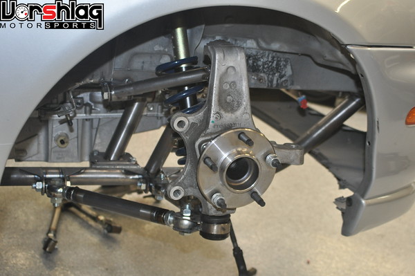
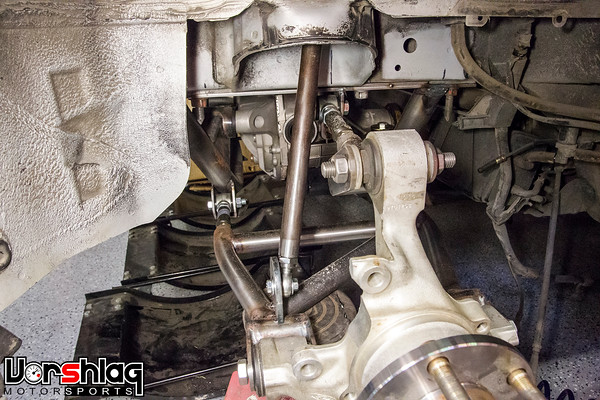
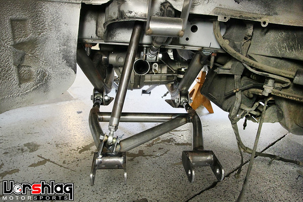
Making this car as a one-off build would have been SO much easier - we would have just notched out part of the frame and made the RX8's control arms pick-up points fit in space where they would work for the geometry. But we have been going to great lengths to keep this subframe and suspension a reproducible kit, and to keep it a purely bolt-on set of parts, which meant not chopping a chunk out of the front frame section to move the upper control arms upwards. In the end we found that the C5 spindles, with the OEM ball joints aimed as they are, allows for the geometry we needed within these MX5 chassis constraints, using these custom control arms. BOOM!
Steering Rack Placement + New Steering Shaft
Once the new front control arms were fabricated and tacked welded, then geometries rechecked (both manually/visually and in software), it was at a good stopping point. Ryan then began to tackle the front steering rack mounting.

The NB Miata steering rack was placed in the ideal location for the slightly altered wheelbase and new front Corvette spindles, keeping in mind the necessary oil pan clearance. We have a half dozen different LSx oil pans around here to test with, so we worked with those to find the right combination to clear the steering rack without adding bumpsteer. The final rack mounts were fabricated and tacked to the crossmember.

This new rack location (and the small wheelbase change) would mean we would need new, slightly longer intermediate steering shaft assembly in the engine bay. Luckily we're used to making those for all of our BMW LSx swaps, so this is another bolt-on solution. What you see above is a mock-up - with one of the two aftermarket steering U-joints installed with a piece of 3/4" Double D shaft, to check lengths. The final solution will be a proper 2-piece collapsible steering shaft assembly like our many Vorshlag BMW steering shaft assemblies (see below). We make these to improve header clearance for V8 swaps on various BMWs, improve the heat resistance of the U-joints (the OEM steering shafts on LHD cars with inline engines are not meant to see exhaust heat) as well as to remove nasty rubber "rag joints" (steering shaft isolators) in the shaft, for better steering feel. We even sell a lot of these steering shafts to BMW racers who keep the BMW engine, just for the improved feel.


Olof took a fresh NB steering rack core and converted it to a de-powered rack (we do this work on NA/NB Miatas often), welding up the bits necessary. We will use no power steering in this car initially, then switch to an electric assist solution if it is deemed necessary.
Front Drive Accessories
Running no power steering pump will create some headaches but also solve some potential problems. Hydraulic fluid power steering assist is always a hassle in any car; the system can make for a huge mess when it leaks, and requires an engine-driven hydraulic pump, reservoir, cooler, and high end hoses on a tracked car. This system is the number one cause of on-track fluid leaks and underhood fires, so taking hydraulic power assist out of the equation is fast becoming part of our track-worthy upgrade list for all cars. Many OEM cars these days are coming with "EPAS" systems from the factory, which makes for aftermarket electric steering assist solutions that are numerous and proven - since many are just re-purposed OEM systems. This means they can even be cost effective. And lighter. And no longer based on flammable, high pressure fluid that robs power from the engine to pressurize. Win!


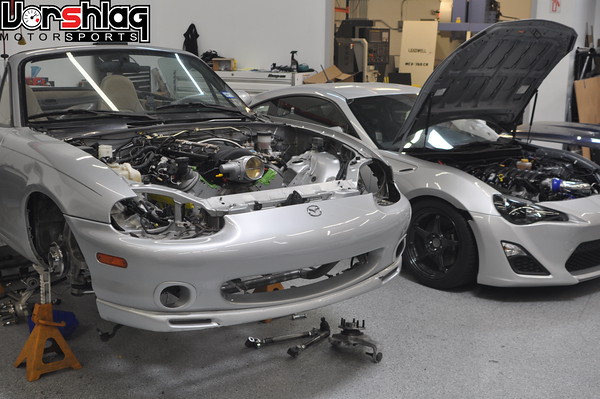
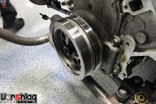
A recent LS1 mock-up (October) with a set of accessories that does NOT have a power steering pump
And while it might seem simple to run any old LSx engine without a power steering pump, it was actually pretty tricky. This particular accessory drive arrangement was figured out on our FR-S LS1 Alpha swap, with some help from the itnernets plus some custom machined bits made here at Vorshlag. That car has an electric assist in the column, so it did not need the pump.


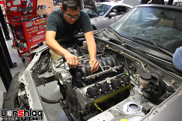
We couldn't find a factory set of LS series engine accessories without the P/S pump, so we went with a proven version that had GOOD front clearance (shown above on the FR-S LS1) and narrow packaging, then the normal main serpentine belt routing was changed to bypass the missing power steering pulley. To accomplish this an extra idler pulley was added, and things were moved around to give proper belt wrap on each pulley - especially the balancer (SFI unit secured with a massive 12-point ARP bolt). We took some measurements then borrowed this set of accessories from the FR-S and test fit onto the built Miata LS1 motor, it fit great (see images above), so we're replicating that set-up now for the Miata. It took a few iterations but we finally got the right length belt (these were the "almosts")
Motor Mounts and Transmission Crossmember Design - With A New Twist
Once the newly modified, de-powered NB steering rack was mounted to the subframe with some beefy, fabricated brackets (see above) we wanted to then lock down the designs for the motor mounts and transmission crossmember. But now that the tubular subframe was built and the rack was tweaked to fit the C5 spindles, Ryan saw some extra room and tried something I didn't expect... he put a Tremec T56 6-speed behind the LSx mock-up motor and stuck it back in the car. Again. Yes, after all the testing and trouble we went through to make the Tremec TKO600 5-speed fit, he went and stuck a T56 in there.

I had told Ryan when he came on board at Vorshlag that the T56 would never fit this car, both because we tried this transmission before (with the OEM crossmember, and then a cut up OEM crossmember) as well as the fact that all of the other LS1 swap kits for the Miata require cutting the tunnel to make the T56 fit this car. "Waste of time."


Thankfully, I was wrong this time. Now the bigger, stronger T56 did fit - and fit with room to spare! Apparently in our previous T56 testing the Miata's OEM front crossmember was the limiting factor. That big, bulky plate steel structure moved the drivetrain up significantly, which is why the T56 never fits the Miata tunnel on most swaps without cutting the tunnel to make room.


Left: The initial LS1/T56 mockups were a bust with the OEM crossmember in place. Right: With the tubular crossmember we have lots more room
continued below

Making this car as a one-off build would have been SO much easier - we would have just notched out part of the frame and made the RX8's control arms pick-up points fit in space where they would work for the geometry. But we have been going to great lengths to keep this subframe and suspension a reproducible kit, and to keep it a purely bolt-on set of parts, which meant not chopping a chunk out of the front frame section to move the upper control arms upwards. In the end we found that the C5 spindles, with the OEM ball joints aimed as they are, allows for the geometry we needed within these MX5 chassis constraints, using these custom control arms. BOOM!
Steering Rack Placement + New Steering Shaft
Once the new front control arms were fabricated and tacked welded, then geometries rechecked (both manually/visually and in software), it was at a good stopping point. Ryan then began to tackle the front steering rack mounting.

The NB Miata steering rack was placed in the ideal location for the slightly altered wheelbase and new front Corvette spindles, keeping in mind the necessary oil pan clearance. We have a half dozen different LSx oil pans around here to test with, so we worked with those to find the right combination to clear the steering rack without adding bumpsteer. The final rack mounts were fabricated and tacked to the crossmember.

This new rack location (and the small wheelbase change) would mean we would need new, slightly longer intermediate steering shaft assembly in the engine bay. Luckily we're used to making those for all of our BMW LSx swaps, so this is another bolt-on solution. What you see above is a mock-up - with one of the two aftermarket steering U-joints installed with a piece of 3/4" Double D shaft, to check lengths. The final solution will be a proper 2-piece collapsible steering shaft assembly like our many Vorshlag BMW steering shaft assemblies (see below). We make these to improve header clearance for V8 swaps on various BMWs, improve the heat resistance of the U-joints (the OEM steering shafts on LHD cars with inline engines are not meant to see exhaust heat) as well as to remove nasty rubber "rag joints" (steering shaft isolators) in the shaft, for better steering feel. We even sell a lot of these steering shafts to BMW racers who keep the BMW engine, just for the improved feel.


Olof took a fresh NB steering rack core and converted it to a de-powered rack (we do this work on NA/NB Miatas often), welding up the bits necessary. We will use no power steering in this car initially, then switch to an electric assist solution if it is deemed necessary.
Front Drive Accessories
Running no power steering pump will create some headaches but also solve some potential problems. Hydraulic fluid power steering assist is always a hassle in any car; the system can make for a huge mess when it leaks, and requires an engine-driven hydraulic pump, reservoir, cooler, and high end hoses on a tracked car. This system is the number one cause of on-track fluid leaks and underhood fires, so taking hydraulic power assist out of the equation is fast becoming part of our track-worthy upgrade list for all cars. Many OEM cars these days are coming with "EPAS" systems from the factory, which makes for aftermarket electric steering assist solutions that are numerous and proven - since many are just re-purposed OEM systems. This means they can even be cost effective. And lighter. And no longer based on flammable, high pressure fluid that robs power from the engine to pressurize. Win!


A recent LS1 mock-up (October) with a set of accessories that does NOT have a power steering pump
And while it might seem simple to run any old LSx engine without a power steering pump, it was actually pretty tricky. This particular accessory drive arrangement was figured out on our FR-S LS1 Alpha swap, with some help from the itnernets plus some custom machined bits made here at Vorshlag. That car has an electric assist in the column, so it did not need the pump.


We couldn't find a factory set of LS series engine accessories without the P/S pump, so we went with a proven version that had GOOD front clearance (shown above on the FR-S LS1) and narrow packaging, then the normal main serpentine belt routing was changed to bypass the missing power steering pulley. To accomplish this an extra idler pulley was added, and things were moved around to give proper belt wrap on each pulley - especially the balancer (SFI unit secured with a massive 12-point ARP bolt). We took some measurements then borrowed this set of accessories from the FR-S and test fit onto the built Miata LS1 motor, it fit great (see images above), so we're replicating that set-up now for the Miata. It took a few iterations but we finally got the right length belt (these were the "almosts")
Motor Mounts and Transmission Crossmember Design - With A New Twist
Once the newly modified, de-powered NB steering rack was mounted to the subframe with some beefy, fabricated brackets (see above) we wanted to then lock down the designs for the motor mounts and transmission crossmember. But now that the tubular subframe was built and the rack was tweaked to fit the C5 spindles, Ryan saw some extra room and tried something I didn't expect... he put a Tremec T56 6-speed behind the LSx mock-up motor and stuck it back in the car. Again. Yes, after all the testing and trouble we went through to make the Tremec TKO600 5-speed fit, he went and stuck a T56 in there.

I had told Ryan when he came on board at Vorshlag that the T56 would never fit this car, both because we tried this transmission before (with the OEM crossmember, and then a cut up OEM crossmember) as well as the fact that all of the other LS1 swap kits for the Miata require cutting the tunnel to make the T56 fit this car. "Waste of time."


Thankfully, I was wrong this time. Now the bigger, stronger T56 did fit - and fit with room to spare! Apparently in our previous T56 testing the Miata's OEM front crossmember was the limiting factor. That big, bulky plate steel structure moved the drivetrain up significantly, which is why the T56 never fits the Miata tunnel on most swaps without cutting the tunnel to make room.


Left: The initial LS1/T56 mockups were a bust with the OEM crossmember in place. Right: With the tubular crossmember we have lots more room
continued below
 12-18-2014, 02:07 PM
#27
continued from above
This is because the LSx/T56 drivetrain is being moved upwards inches from where we have our drivetrain. With our latest (version 2.0) bolt-in tubular front crossmember, the engine sits lower and so does the transmission, so now it fits. It still has ample ground clearance to the oil pan, which is tucked up just above the bottom of the crossmember and bottom of the Miata tub. The T56 shifter location lines up perfectly with the factory Miata shifter hole. Moving this drivetrain down worked another miracle, and it lowers the CG, too. Win-win.
That big transmission change threw me for a loop, but so be it! A brand new Tremec T56 Magnum costs more than the TKO600 new, but not by much, and its a more popular trans so we called up our Tremec supplier and we had a brand new close-ratio T56 Magnum on hand the next day.

Tremec T56 Magnum - close ratio version - rated to 700 ft-lbs of torque!
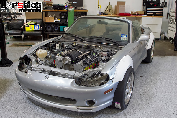
If you know anyone that needs a GM-style TKO600, brand new, we will have it listed for sale here until it is gone, for less than they sell for now. We still have to get the correct flywheel, clutch and pressure plate for the T56, but those bits are already on order and should be here next week. During all of the transmission testing our crew removed the mock-up LS1 motor for the last time and installed the built 5.7L LS1 that the Alpha customer purchased for this build, made by the masters at HK Racing Engines.


Left: The built LS1 with borrowed accessories and LS3 intake in the Miata: Right: LS1 with same accessories and balancer in FR-S
This motor has a built bottom end, CNC ported heads, big lumpy cam, proper valvetrain, and all sorts of race parts inside. Should make in the neighborhood of 450 whp on pump gas. Ryan chose the 98-02 Camaro oil pan during his testing, so we ordered an Improved Racing oil pan baffle kit to fit this pan and that's in place. We won't build a track-duty car with an LSx without an oil pan baffle from Improved Racing. After talking to those guys at SEMA they realized how many of these LSx baffle kits we've used over the years and made us a dealer, so we'll add these to our website shortly.


Left: The accessory arrangement we used has ample room for an A/C compressor, as shown. Right: Improved Racing oil pan baffle will be used
Once the oil pan and accessories were locked down, then Ryan could start to build the motor mounts (see below left), which he knocked out in about a day. These look like many of the designs we have used on BMW E36, BMW E46, BMW E30 and the FR-S/BRZ swaps done here at Vorshlag.

A production set of similar mounts for our BMW E46 LS1 swap, black gloss powder coated. We make these in-house with CNC laser cut pieces
When you have a robust, proven design that has been made 100s of times, you use it. These make for a strong, reliable, low vibration mount that has no movement when torque is applied. These then bolt to a gusseted, plate structure welded to the tubular subframe (see below right).


To make the transmission crossmember required a bit of extra work, at least on this Alpha build. Like on the FR-S swap (after we made room for the longer T56 Magnum XL we used on that car) this NB Miata chassis has no transmission crossmember mounting on the chassis. The front mounting points of the "PPF" on the NA/NB Miata is the transmission mount (which is similar to Corvettes from C4-C7), but we ditched that since the T56 Magnum had no provisions for mounting this ladder frame to the back of the tail housing. Modifying the transmission to fit the factory PPF would be a nightmare to reproduce in kit form.


Left: The heavy stock dash was removed to make room to pull the carpet. Center: Inner plate brackets. Right: Shifter lines up very closely
To make room for the next step, the dash was removed. Why? Two reasons. First, we wanted to see how much the entire NB dash structure weighed. 49 pounds is the answer. Second, to remove the OEM carpet intact the dash has to come out. We needed to add some backing plates inside the tunnel under the carpet, to hold the transmission crossmember brackets inside the tunnel, so the carpet was pulled. For the kit version we'll have templates for where to drill holes and you can slit the carpet to slide the plates under the carpet without removing all of this, hopefully. Mazda just makes it extra hard to remove the carpet on these cars - dash and everything is in the way.


Left: Outer tunnel reinforcement plates. Right: The transmission crossmember bolts to inner tunnel reinforcement plate mounts
As we did on the FR-S swap, mounting plates were bolted to the chassis on both sides of the transmission tunnel. These can stay in place, and the crossmember then bolts to the inner mounting bracket plates. This sandwich of plates (one set inside the tunnel and the matching plates inside the cabin) makes for a strong mounting arrangement which we've used in the past. The removable crossmember bolts to those inboard mounting plates and this, in turn, is what the transmission bolts to.

The raw steel crossmember shown above is semi-finished; we will add more gussets when we final weld the assembly. It has lower reliefs that could clear up to two 4" diameter exhaust tubes, but we will build this car with a dual 3" exhaust - which still has massive flow potential. We used our proven red polyurethane transmission mount bushing from other T56 swaps in this set-up, but we also make a machined Nylon busing for a pure race car.
continued below
This is because the LSx/T56 drivetrain is being moved upwards inches from where we have our drivetrain. With our latest (version 2.0) bolt-in tubular front crossmember, the engine sits lower and so does the transmission, so now it fits. It still has ample ground clearance to the oil pan, which is tucked up just above the bottom of the crossmember and bottom of the Miata tub. The T56 shifter location lines up perfectly with the factory Miata shifter hole. Moving this drivetrain down worked another miracle, and it lowers the CG, too. Win-win.
That big transmission change threw me for a loop, but so be it! A brand new Tremec T56 Magnum costs more than the TKO600 new, but not by much, and its a more popular trans so we called up our Tremec supplier and we had a brand new close-ratio T56 Magnum on hand the next day.

Tremec T56 Magnum - close ratio version - rated to 700 ft-lbs of torque!
If you know anyone that needs a GM-style TKO600, brand new, we will have it listed for sale here until it is gone, for less than they sell for now. We still have to get the correct flywheel, clutch and pressure plate for the T56, but those bits are already on order and should be here next week. During all of the transmission testing our crew removed the mock-up LS1 motor for the last time and installed the built 5.7L LS1 that the Alpha customer purchased for this build, made by the masters at HK Racing Engines.


Left: The built LS1 with borrowed accessories and LS3 intake in the Miata: Right: LS1 with same accessories and balancer in FR-S
This motor has a built bottom end, CNC ported heads, big lumpy cam, proper valvetrain, and all sorts of race parts inside. Should make in the neighborhood of 450 whp on pump gas. Ryan chose the 98-02 Camaro oil pan during his testing, so we ordered an Improved Racing oil pan baffle kit to fit this pan and that's in place. We won't build a track-duty car with an LSx without an oil pan baffle from Improved Racing. After talking to those guys at SEMA they realized how many of these LSx baffle kits we've used over the years and made us a dealer, so we'll add these to our website shortly.


Left: The accessory arrangement we used has ample room for an A/C compressor, as shown. Right: Improved Racing oil pan baffle will be used
Once the oil pan and accessories were locked down, then Ryan could start to build the motor mounts (see below left), which he knocked out in about a day. These look like many of the designs we have used on BMW E36, BMW E46, BMW E30 and the FR-S/BRZ swaps done here at Vorshlag.
A production set of similar mounts for our BMW E46 LS1 swap, black gloss powder coated. We make these in-house with CNC laser cut pieces
When you have a robust, proven design that has been made 100s of times, you use it. These make for a strong, reliable, low vibration mount that has no movement when torque is applied. These then bolt to a gusseted, plate structure welded to the tubular subframe (see below right).


To make the transmission crossmember required a bit of extra work, at least on this Alpha build. Like on the FR-S swap (after we made room for the longer T56 Magnum XL we used on that car) this NB Miata chassis has no transmission crossmember mounting on the chassis. The front mounting points of the "PPF" on the NA/NB Miata is the transmission mount (which is similar to Corvettes from C4-C7), but we ditched that since the T56 Magnum had no provisions for mounting this ladder frame to the back of the tail housing. Modifying the transmission to fit the factory PPF would be a nightmare to reproduce in kit form.


Left: The heavy stock dash was removed to make room to pull the carpet. Center: Inner plate brackets. Right: Shifter lines up very closely
To make room for the next step, the dash was removed. Why? Two reasons. First, we wanted to see how much the entire NB dash structure weighed. 49 pounds is the answer. Second, to remove the OEM carpet intact the dash has to come out. We needed to add some backing plates inside the tunnel under the carpet, to hold the transmission crossmember brackets inside the tunnel, so the carpet was pulled. For the kit version we'll have templates for where to drill holes and you can slit the carpet to slide the plates under the carpet without removing all of this, hopefully. Mazda just makes it extra hard to remove the carpet on these cars - dash and everything is in the way.


Left: Outer tunnel reinforcement plates. Right: The transmission crossmember bolts to inner tunnel reinforcement plate mounts
As we did on the FR-S swap, mounting plates were bolted to the chassis on both sides of the transmission tunnel. These can stay in place, and the crossmember then bolts to the inner mounting bracket plates. This sandwich of plates (one set inside the tunnel and the matching plates inside the cabin) makes for a strong mounting arrangement which we've used in the past. The removable crossmember bolts to those inboard mounting plates and this, in turn, is what the transmission bolts to.

The raw steel crossmember shown above is semi-finished; we will add more gussets when we final weld the assembly. It has lower reliefs that could clear up to two 4" diameter exhaust tubes, but we will build this car with a dual 3" exhaust - which still has massive flow potential. We used our proven red polyurethane transmission mount bushing from other T56 swaps in this set-up, but we also make a machined Nylon busing for a pure race car.
continued below
12-18-2014, 02:08 PM
#28
continued from above
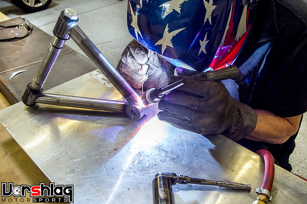
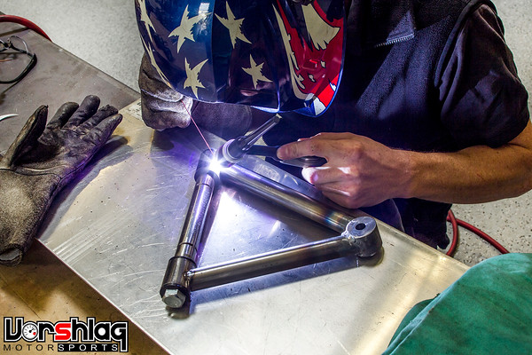
Subframe Final Welding - Times Two


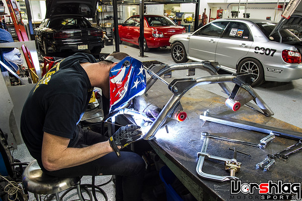
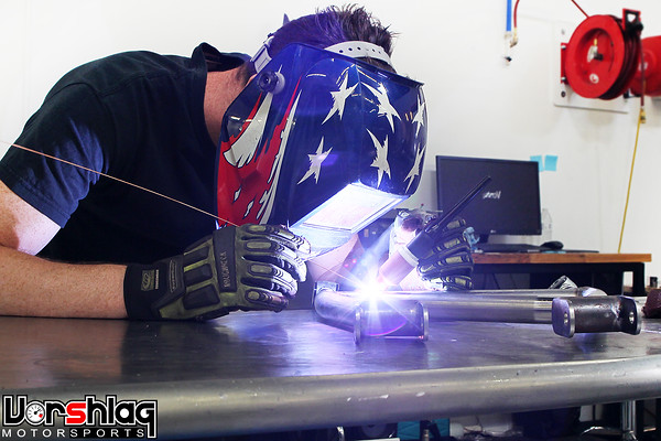
After the drivetrain mounting was designed and built, the motor was once again removed and the tack welded front subframe came out for final welding. This step took two solid days, as welding fixtures had to be built and then additional gussets had to be made and welded in place as Ryan went through the tacked joints and TIG welded everything. The end result is shown below, and is a very strong work of art. Production fixtures would key all sorts of CNC laser cut pieces into place, and that is much more elaborate, but we will make those when we blow the car apart for the last time.


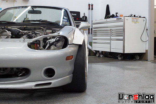
After the front subframe was finish welded they put it back into the chassis (raw), installed the steering rack, mocked up the steering shaft with the new forged U-joints, and shop manager Brad shot the pics below. We will keep the fabricated bits in raw steel until after the initial road & track testing is completed, so if we need to make any changes we're not grinding a powder coated finish off to add something.


Last week Ryan removed the rear subframe assembly from the car (at that point still just tack welded) and got to work finish welding that. As with the front subframe, he added gusset plates here and there, boxed in a lot of structures, and TIG seam welded everything as he went. He also built several welding fixtures to keep everything straight and true during welding.


He's finished with the bulk of the work on the rear subframe now (we will still add a reinforcing plate or "X" tubular structure to the bottom - he adding mounting tabs for this) and the project is just awaiting a big shipment of parts before we jump to the next step. We have put a few teaser pics out there during these various fabrication steps and people have really liked what they have seen, and we even have people already in line for these kits. So yes, we're going to have to produce all of this in kit form. It might end up a bit pricier than other kits out there, so we may make them in pretty low volumes, but this will not be our last V8 Miata.... no no no.


What's not to like? The weight will still be at or under 2500 pounds, with a 6-speed capable of taking 700 ft-lbs of torque, the motor we have for this will make 450+ whp and you can make 600 whp on pump gas with a little bit more spent. We're upgrading ALL of the weak points of NB Miatas and previous V8 swaps, with the move to C5 spindles/wheel bearings and the rear hubs we've used. The Ford 8.8" aluminum IRS center section is super stout and has lots of LSD options. Its going to be a potent little beast.

So that's what we have been up to on this Alpha Miata V8 over the past 5 months: we tweaked and measured the RX8 bits, made a brand new front crossmember, chucked the RX8 bits, made another all new front suspension with Corvette spindles and brakes, made a T56 possible without cutting the tunnel up, finish welded the tubular subframe assemblies on both ends, finish welded the custom suspension bits, and everything so far is a bolt-in (except the two notched sections at the back of the engine bay). Should be kit-able. Should be fun.
What's Next?
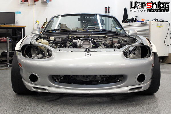
The flywheel, clutch and bellhousing are ordered and should be here in the next week or two. Same goes for the final front engine accessories and brackets - the borrowed set shown is already back on the FR-S. The next big step is fabricating the full length stainless headers.


Left: Vorshlag built full length prototype headers for Scion FR-S LSx. Right: Production CNC bent stainless headers for Vorshlag BMW E46 LSx
We finished the custom prototype set of full length headers about 6-8 weeks ago on the FR-S and last week we tested the 2nd production iteration, and its almost perfect. Making the prototype headers, bend by bend, is a tedious process. We use a few tricks (the plastic snap-together bends help mockup) but it still takes more than 40 hours to make the first set. With materials and our shop rate that would be over $5000, which is crazy - but that's what one-off set of stainless full length headers cost for a V8. Of course we will we have the prototypes transferred digitally in 3D, then have the tubes CNC bent, and production headers made in batches of about 10 sets - which pulls the retail price for these swap headers down around $1700.
continued below
Subframe Final Welding - Times Two


After the drivetrain mounting was designed and built, the motor was once again removed and the tack welded front subframe came out for final welding. This step took two solid days, as welding fixtures had to be built and then additional gussets had to be made and welded in place as Ryan went through the tacked joints and TIG welded everything. The end result is shown below, and is a very strong work of art. Production fixtures would key all sorts of CNC laser cut pieces into place, and that is much more elaborate, but we will make those when we blow the car apart for the last time.


After the front subframe was finish welded they put it back into the chassis (raw), installed the steering rack, mocked up the steering shaft with the new forged U-joints, and shop manager Brad shot the pics below. We will keep the fabricated bits in raw steel until after the initial road & track testing is completed, so if we need to make any changes we're not grinding a powder coated finish off to add something.


Last week Ryan removed the rear subframe assembly from the car (at that point still just tack welded) and got to work finish welding that. As with the front subframe, he added gusset plates here and there, boxed in a lot of structures, and TIG seam welded everything as he went. He also built several welding fixtures to keep everything straight and true during welding.


He's finished with the bulk of the work on the rear subframe now (we will still add a reinforcing plate or "X" tubular structure to the bottom - he adding mounting tabs for this) and the project is just awaiting a big shipment of parts before we jump to the next step. We have put a few teaser pics out there during these various fabrication steps and people have really liked what they have seen, and we even have people already in line for these kits. So yes, we're going to have to produce all of this in kit form. It might end up a bit pricier than other kits out there, so we may make them in pretty low volumes, but this will not be our last V8 Miata.... no no no.


What's not to like? The weight will still be at or under 2500 pounds, with a 6-speed capable of taking 700 ft-lbs of torque, the motor we have for this will make 450+ whp and you can make 600 whp on pump gas with a little bit more spent. We're upgrading ALL of the weak points of NB Miatas and previous V8 swaps, with the move to C5 spindles/wheel bearings and the rear hubs we've used. The Ford 8.8" aluminum IRS center section is super stout and has lots of LSD options. Its going to be a potent little beast.

So that's what we have been up to on this Alpha Miata V8 over the past 5 months: we tweaked and measured the RX8 bits, made a brand new front crossmember, chucked the RX8 bits, made another all new front suspension with Corvette spindles and brakes, made a T56 possible without cutting the tunnel up, finish welded the tubular subframe assemblies on both ends, finish welded the custom suspension bits, and everything so far is a bolt-in (except the two notched sections at the back of the engine bay). Should be kit-able. Should be fun.
What's Next?
The flywheel, clutch and bellhousing are ordered and should be here in the next week or two. Same goes for the final front engine accessories and brackets - the borrowed set shown is already back on the FR-S. The next big step is fabricating the full length stainless headers.


Left: Vorshlag built full length prototype headers for Scion FR-S LSx. Right: Production CNC bent stainless headers for Vorshlag BMW E46 LSx
We finished the custom prototype set of full length headers about 6-8 weeks ago on the FR-S and last week we tested the 2nd production iteration, and its almost perfect. Making the prototype headers, bend by bend, is a tedious process. We use a few tricks (the plastic snap-together bends help mockup) but it still takes more than 40 hours to make the first set. With materials and our shop rate that would be over $5000, which is crazy - but that's what one-off set of stainless full length headers cost for a V8. Of course we will we have the prototypes transferred digitally in 3D, then have the tubes CNC bent, and production headers made in batches of about 10 sets - which pulls the retail price for these swap headers down around $1700.
continued below
12-18-2014, 02:08 PM
#29
continued from above
Seems like a lot until you consider that these are very low volume production parts made for an engine swap, unlike typical high volume "store bought" headers. These are also made from real 304 stainless, have proper merge collectors and V-bands, and are 100% made in the USA. The full length 1.75" primary design tends to add about 40-50 whp over stock manifolds or block-hugger style headers. And proper full length exhaust headers like these adds "guilt free power" over manifolds or shorties, with no downsides. These will add power to low, middle and upper RPM ranges alike. In our experience, the myth about "long tube headers killing torque" is utter nonsense. No, they won't be Tri-Y designs, nor will the primaries be perfectly equal in length, they will be the best headers that can fit the confines of this chassis/subframe/engine, with the least number of restrictive bends - that works better than "equal length" headers with tons of unnecessary, tortured bends.


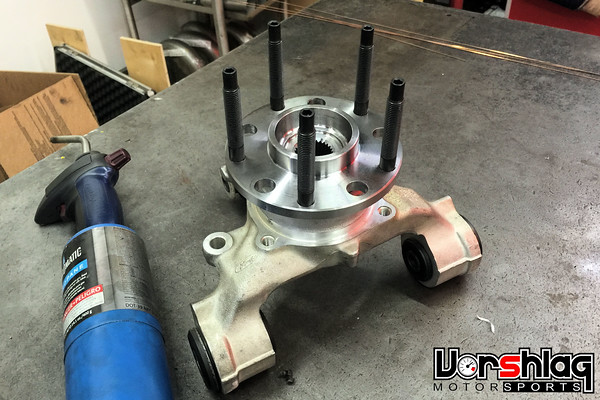
We still need to make the driveshaft and halfshafts, then pick the final wheel sizes and get those built to order on the car. We will re-drill the rear hubs to match the fronts (rear is Ford 5-lug, front is GM 5-lug; our new CNC mill will make quick work of that). And we still have to do the cooling, and plumbing, and wiring, and fuel. It seems daunting but honestly, the hardest parts of this swap are behind us - the all new subframes and custom suspension arms were the BIG development hurdles on this project. You will now see a lot of what we learned on previous BMW V8 swaps and the current FR-S V8 swap on the rest of Miata, and those V8 swap experiences over the past 12 years will help us get this one to the finish line. The Miata swap is much more extensive (since it needed hubs, suspension, diff, and entire subframes) than others in the past we have built, which has made this one take us a bit longer than we'd like - but doing it right takes time.
A lot of folks keep asking us - when will this be done? And my answer is - its done when its done. The owner of this car has been extremely patient, but when you are an Alpha customer for a new swap like this, the shop ends up eating $20-30K+ in labor for the first build (hundreds of hours of research, testing, trial/error, fixturing, and hand built fabrications), so that's what their patience nets them.


Once the wheels and tires are picked and installed we can make some flares to cover the (likely) 285/30/18s at all four corners. We just went through this work on my TT3 prepped 2011 Mustang and Ryan built some beautiful metal fender flares to cover 335mm front tires (which go with the 345mm tires and rear flares the car already had). We can do the same work on the Miata, no problem. The owner of the car, Jason, is picking up a fiberglass front end that should work better with the wider track width and we'll tie the flares into that.

And YES, one more time, we plan on making a kit for all of this - tubular front subframe, tubular rear subframe for 8.8" Ford IRS, control arms, motor mounts, transmission crossmember, driveshaft, halfshafts, uprights, hubs, steering shaft, and headers - on the first round of swap part releases. Much more will be developed after that "Stage 0" round of major parts is in production (like plumbing, cooling, wiring, and fuel system solutions). These bits will only be available after this car is road tested. We will post up a few more times before that happens, so just subscribe to this thread and you'll be the first to know. That's how we've done all of our BMW kits (120+ kits sold) in the past - get a car built, then release the major drivetrain related mounting bits + headers, then release the sub-system solutions after that.
More soon,
Seems like a lot until you consider that these are very low volume production parts made for an engine swap, unlike typical high volume "store bought" headers. These are also made from real 304 stainless, have proper merge collectors and V-bands, and are 100% made in the USA. The full length 1.75" primary design tends to add about 40-50 whp over stock manifolds or block-hugger style headers. And proper full length exhaust headers like these adds "guilt free power" over manifolds or shorties, with no downsides. These will add power to low, middle and upper RPM ranges alike. In our experience, the myth about "long tube headers killing torque" is utter nonsense. No, they won't be Tri-Y designs, nor will the primaries be perfectly equal in length, they will be the best headers that can fit the confines of this chassis/subframe/engine, with the least number of restrictive bends - that works better than "equal length" headers with tons of unnecessary, tortured bends.


We still need to make the driveshaft and halfshafts, then pick the final wheel sizes and get those built to order on the car. We will re-drill the rear hubs to match the fronts (rear is Ford 5-lug, front is GM 5-lug; our new CNC mill will make quick work of that). And we still have to do the cooling, and plumbing, and wiring, and fuel. It seems daunting but honestly, the hardest parts of this swap are behind us - the all new subframes and custom suspension arms were the BIG development hurdles on this project. You will now see a lot of what we learned on previous BMW V8 swaps and the current FR-S V8 swap on the rest of Miata, and those V8 swap experiences over the past 12 years will help us get this one to the finish line. The Miata swap is much more extensive (since it needed hubs, suspension, diff, and entire subframes) than others in the past we have built, which has made this one take us a bit longer than we'd like - but doing it right takes time.
A lot of folks keep asking us - when will this be done? And my answer is - its done when its done. The owner of this car has been extremely patient, but when you are an Alpha customer for a new swap like this, the shop ends up eating $20-30K+ in labor for the first build (hundreds of hours of research, testing, trial/error, fixturing, and hand built fabrications), so that's what their patience nets them.


Once the wheels and tires are picked and installed we can make some flares to cover the (likely) 285/30/18s at all four corners. We just went through this work on my TT3 prepped 2011 Mustang and Ryan built some beautiful metal fender flares to cover 335mm front tires (which go with the 345mm tires and rear flares the car already had). We can do the same work on the Miata, no problem. The owner of the car, Jason, is picking up a fiberglass front end that should work better with the wider track width and we'll tie the flares into that.

And YES, one more time, we plan on making a kit for all of this - tubular front subframe, tubular rear subframe for 8.8" Ford IRS, control arms, motor mounts, transmission crossmember, driveshaft, halfshafts, uprights, hubs, steering shaft, and headers - on the first round of swap part releases. Much more will be developed after that "Stage 0" round of major parts is in production (like plumbing, cooling, wiring, and fuel system solutions). These bits will only be available after this car is road tested. We will post up a few more times before that happens, so just subscribe to this thread and you'll be the first to know. That's how we've done all of our BMW kits (120+ kits sold) in the past - get a car built, then release the major drivetrain related mounting bits + headers, then release the sub-system solutions after that.
More soon,
12-18-2014, 02:32 PM
#30
V8 Miata Fan

I just read the new update on your blog, looks great. How does the engine placement compare to the V8R kit? In the pics it looks like it might not be quite as far to the rear but it's hard to tell for sure.
12-18-2014, 04:41 PM
#31
V8 Miata Noob

Join Date: Jan 2014
Posts: 2
Likes: 0
Received 0 Likes
on
0 Posts
It's as far to the rear as it can go with the gussets cut out of the engine compartment, and a little bit lower.
The easy way to check front-to-rear engine placement is to look at where the shifter ends up relative to the stock shifter opening.
The easy way to check front-to-rear engine placement is to look at where the shifter ends up relative to the stock shifter opening.


 12-20-2014, 11:48 PM
#34
Administrator

Everything looks fantastic and we appreciate the documentation of the development of your eventual kit but please remember that your current membership status does not allow you to "sell" anything via this thread. As you are a business posting as a member, not a sponsor, the line between promotion of that business and promotion of the focus of this forum is already thin and at times nebulous. As of this point the fact that you currently do not sell anything related to V8 Miata builds is what is keeping this thread open. When your kit is ready to sell if you wish to do so here please remember that you will have to upgrade your membership at that time.
Until that point ANY reference to price or availability of a V8 Miata related product will be removed. If any members have a question regarding such topics please keep the discussion off-forum until Vorshlag-Fair becomes a sponsor of the site.
Thank you everyone, including Vorshlag-Fair, for your understanding with this. In order to keep this forum going we need to attract actual new sponsors to keep the lights on and will not be able to do so if we do not keep the lines between member-level and sponsor-level forum usage clear.
Please keep posting your progress with this. The information is exceptionally useful to our members looking to build their own LSx conversions and will serve as a good lead in for you should you eventually decide to start supporting our community as a sponsor.
Again, thank you everyone for your understanding,
-Jason
12-23-2014, 04:10 PM
#35
V8 Miata Fanatic


It's great to see the progress continuing and the various solutions you come up with from your point of view. It's hard to take my eyes off of the whole rear sub-frame - I just love that for some reason! And now with C5/C6 vette hubs, this thing is becoming even more of a baby Vette. That's a baby Vette that will devour full-figure, overweight GM Vettes on any given day! Just gotta love that.
Keep it going and we look forward to your products and perhaps being a sponsor/ vendor on V8M.net.
Keep it going and we look forward to your products and perhaps being a sponsor/ vendor on V8M.net.
11-11-2015, 07:24 PM
#37
Everything looks fantastic and we appreciate the documentation of the development of your eventual kit but please remember that your current membership status does not allow you to "sell" anything via this thread. As you are a business posting as a member, not a sponsor, the line between promotion of that business and promotion of the focus of this forum is already thin and at times nebulous. As of this point the fact that you currently do not sell anything related to V8 Miata builds is what is keeping this thread open. When your kit is ready to sell if you wish to do so here please remember that you will have to upgrade your membership at that time.
Until that point ANY reference to price or availability of a V8 Miata related product will be removed. If any members have a question regarding such topics please keep the discussion off-forum until Vorshlag-Fair becomes a sponsor of the site.
Thank you everyone, including Vorshlag-Fair, for your understanding with this. In order to keep this forum going we need to attract actual new sponsors to keep the lights on and will not be able to do so if we do not keep the lines between member-level and sponsor-level forum usage clear.
Please keep posting your progress with this. The information is exceptionally useful to our members looking to build their own LSx conversions and will serve as a good lead in for you should you eventually decide to start supporting our community as a sponsor.
Again, thank you everyone for your understanding,
-Jason
Until that point ANY reference to price or availability of a V8 Miata related product will be removed. If any members have a question regarding such topics please keep the discussion off-forum until Vorshlag-Fair becomes a sponsor of the site.
Thank you everyone, including Vorshlag-Fair, for your understanding with this. In order to keep this forum going we need to attract actual new sponsors to keep the lights on and will not be able to do so if we do not keep the lines between member-level and sponsor-level forum usage clear.
Please keep posting your progress with this. The information is exceptionally useful to our members looking to build their own LSx conversions and will serve as a good lead in for you should you eventually decide to start supporting our community as a sponsor.
Again, thank you everyone for your understanding,
-Jason
Feel free to delete this entire thread if that's a problem. The other I-B forums did.
11-11-2015, 09:09 PM
#38
Jim Stainer

Whoa there Terry no one is accusing you of anything and no way will this great thread be deleted. EVER! Jason is just drawing the distinction between a regular guy building on jack stands and shop building a pro kit. He clearly said there is nothing wrong with what you have posted and the comments show this group wants to keep up with what is going on with the Vorshlag Miata. We are a small community here of like minded folks and IB pretty much leaves things and us alone. The only crime here is it's been damn near a year since you posted!
So any updates PLEASE???
So any updates PLEASE???
11-12-2015, 06:33 AM
#39
V8 Miata Fanatic

 11-12-2015, 09:11 AM
#40
Project Update for November 11, 2015: It has been a long time since my last update on the Alpha Miata LS1 swap build thread, so we have a lot to cover in this update. This project was on hold for a while, but was put back on the schedule in July. Since then the front and rear suspensions were wrapped up enough to put the car on the ground, wheels and tires mounted and tested, bodykit mocked up, engine's intake and accessory drive finished, and more.
Our first LS1 powered Scion FR-S (shown above right, next to the LS1 Miata) was completed enough for the customer to start driving it during that 6 month hiatus in the Miata project, and we developed some new things on that swap that will help us on the Miata. The FR-S recently came back for some follow-up development and I will update that build thread soon.
Difficult Realizations
There were many things going on behind the scenes that held up progress on this build for the first half of 2015. Obviously this project has moved beyond the original scope, because it became much more than just a "bolt in swap kit".
As we moved from section to section and addressed the weak points, the project began to fall well outside the realm of just a V8 swap kit. We were dedicated early on to removing all of the weak links that we often see fail with track abuse in other V8 Miata swaps, namely the front hubs and rear hubs, the rear halfshafts, as well as the need to upgrade the OEM brakes and control arms to deal with massive engine torque and tire grip. Addressing those issues in a kitable format was going to take serious added engineering and fabrication hours, more than we could every hope to recoup with kit sales. So the decision was made to do this car as a one-off, making both the engineering and fabrication easier and saving hours and hours of unbilled development time.
The customer and I had a good conversation in late June, after we both did some research into other Miata V8 swap costs. This is when we realized where reality was: With many turn-key swaps for V8 Miata's costing $50K (minus the chassis), our revised numbers for a one-off build didn't look so far out of the realm of possibility. We all agreed to some compromises and then moved forward. This delay ate up several months this year but we were back on track late this summer.
Does that mean we will no longer offer the finished work in kit form? After a hard look at the costs, I doubt it will be at a price point most people will want to pay for a home-built swap kit. Of course we can replicate these parts on the Alpha V8 Miata as a turn-key installation for others. Will it be cheap? No, but it won't be out of the range of other turn-key Miata LS1 swaps.
I feel that the end result will make for a pretty durable and damned fast track car that can still be street driven. It might end up being the only Miata V8 ever build to this level of insanity (this customer asked for "crazy"), but that's not necessarily a bad thing either. Let's look at some progress!
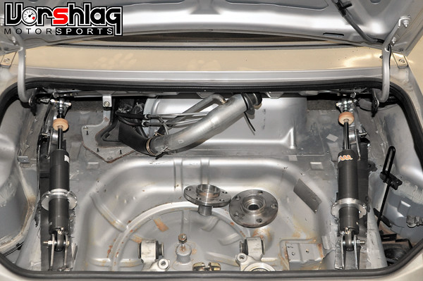
Rear Suspension Change and Major Progress
The final steps of finishing the rear suspension were pretty tricky on this car. Due to some challenges we had to think outside the box to get to the finish line.
We have taken a car made for small brakes, small halfshafts/hubs, and small wheels and tires and jammed a massive 8.8" Ford diff in there, big aluminum uprights from a RWD V8 powered production car, and are building all of this around an 18x10" wheel and 285/30/18 tire out back.
Once the custom upper and lower control arms were built and the halfshafts mocked up, it was clear there was not enough room for a coilover rear shock and spring in the normal location. We tried it upside down, right-side up, moving the upper and lower mounts this way and that - no chance. The rear suspension upright layout we are using made it impossible to fit the spring and shock there.
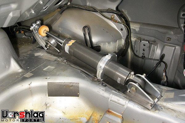
It was just a matter of space - there wasn't enough of it. So I decided to change the rear shock layout into a pushrod/bellcrank style, and move the spring and shock into the trunk. What the what?!
This took a lot of work - mock-ups, calculations, CAD design, CAM programming, CNC machining, fabrication, and testing - but it is in place and we now have the shocks mounted in the trunk. The suspension moves up and down and all of the motions look good, and everything is overbuilt and strong.
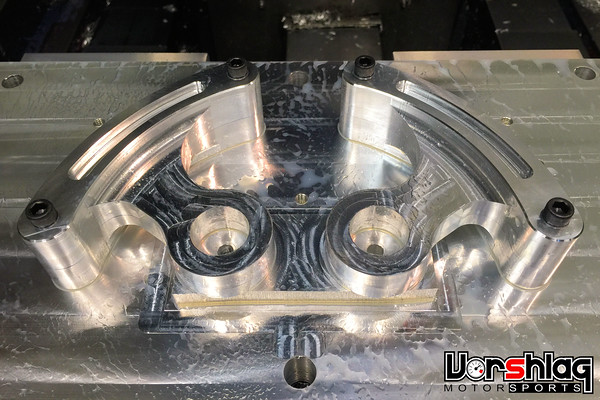
A big chunk of billet aluminum was used to make the pair of bell cranks in multiple steps on the CNC mill, which was a good use of our new CNC machines and skills that we added in January 2015. We bought CNC machines to make ALL of our production Vorshlag components in house, but this also allows us to make custom one-off things like these Miata rear bell cranks.
We didn't go to pushrod actuated inboard suspension to be cute, but out of necessity. The bigger, stronger rear suspension and driveline parts we felt were warranted in this V8 build just ate up too much room, and we had to spend more hours to move things around (most of which were unbillable development hours).
continued below

Our first LS1 powered Scion FR-S (shown above right, next to the LS1 Miata) was completed enough for the customer to start driving it during that 6 month hiatus in the Miata project, and we developed some new things on that swap that will help us on the Miata. The FR-S recently came back for some follow-up development and I will update that build thread soon.
Difficult Realizations
There were many things going on behind the scenes that held up progress on this build for the first half of 2015. Obviously this project has moved beyond the original scope, because it became much more than just a "bolt in swap kit".
As we moved from section to section and addressed the weak points, the project began to fall well outside the realm of just a V8 swap kit. We were dedicated early on to removing all of the weak links that we often see fail with track abuse in other V8 Miata swaps, namely the front hubs and rear hubs, the rear halfshafts, as well as the need to upgrade the OEM brakes and control arms to deal with massive engine torque and tire grip. Addressing those issues in a kitable format was going to take serious added engineering and fabrication hours, more than we could every hope to recoup with kit sales. So the decision was made to do this car as a one-off, making both the engineering and fabrication easier and saving hours and hours of unbilled development time.

The customer and I had a good conversation in late June, after we both did some research into other Miata V8 swap costs. This is when we realized where reality was: With many turn-key swaps for V8 Miata's costing $50K (minus the chassis), our revised numbers for a one-off build didn't look so far out of the realm of possibility. We all agreed to some compromises and then moved forward. This delay ate up several months this year but we were back on track late this summer.
Does that mean we will no longer offer the finished work in kit form? After a hard look at the costs, I doubt it will be at a price point most people will want to pay for a home-built swap kit. Of course we can replicate these parts on the Alpha V8 Miata as a turn-key installation for others. Will it be cheap? No, but it won't be out of the range of other turn-key Miata LS1 swaps.
I feel that the end result will make for a pretty durable and damned fast track car that can still be street driven. It might end up being the only Miata V8 ever build to this level of insanity (this customer asked for "crazy"), but that's not necessarily a bad thing either. Let's look at some progress!
Rear Suspension Change and Major Progress
The final steps of finishing the rear suspension were pretty tricky on this car. Due to some challenges we had to think outside the box to get to the finish line.

We have taken a car made for small brakes, small halfshafts/hubs, and small wheels and tires and jammed a massive 8.8" Ford diff in there, big aluminum uprights from a RWD V8 powered production car, and are building all of this around an 18x10" wheel and 285/30/18 tire out back.

Once the custom upper and lower control arms were built and the halfshafts mocked up, it was clear there was not enough room for a coilover rear shock and spring in the normal location. We tried it upside down, right-side up, moving the upper and lower mounts this way and that - no chance. The rear suspension upright layout we are using made it impossible to fit the spring and shock there.

It was just a matter of space - there wasn't enough of it. So I decided to change the rear shock layout into a pushrod/bellcrank style, and move the spring and shock into the trunk. What the what?!

This took a lot of work - mock-ups, calculations, CAD design, CAM programming, CNC machining, fabrication, and testing - but it is in place and we now have the shocks mounted in the trunk. The suspension moves up and down and all of the motions look good, and everything is overbuilt and strong.

A big chunk of billet aluminum was used to make the pair of bell cranks in multiple steps on the CNC mill, which was a good use of our new CNC machines and skills that we added in January 2015. We bought CNC machines to make ALL of our production Vorshlag components in house, but this also allows us to make custom one-off things like these Miata rear bell cranks.

We didn't go to pushrod actuated inboard suspension to be cute, but out of necessity. The bigger, stronger rear suspension and driveline parts we felt were warranted in this V8 build just ate up too much room, and we had to spend more hours to move things around (most of which were unbillable development hours).
continued below
The following users liked this post:
charchri4 (11-12-2015)
11-12-2015, 09:13 AM
#41
continued from above
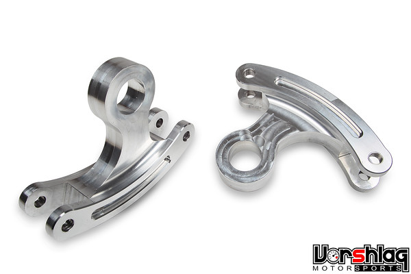
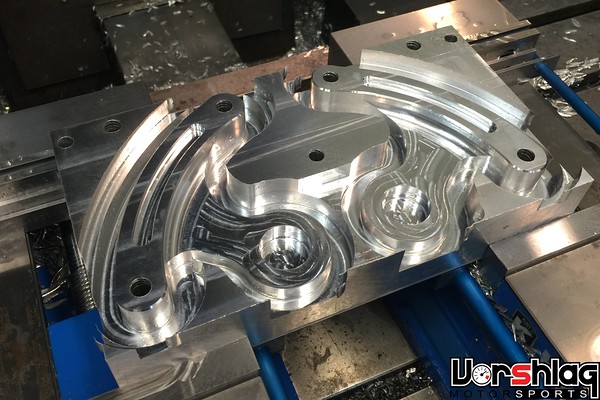
I will go into more details on this rear suspension once we have done some road testing, but so far I'm happy with the results. The bell cranks were CNC machined in custom fixtures over 3 operations to make the completed bits. Radial ball bearings were installed for the pivots and rod-ends are attached at each end of the bell crank - one to the pushrod and the other to the shock.
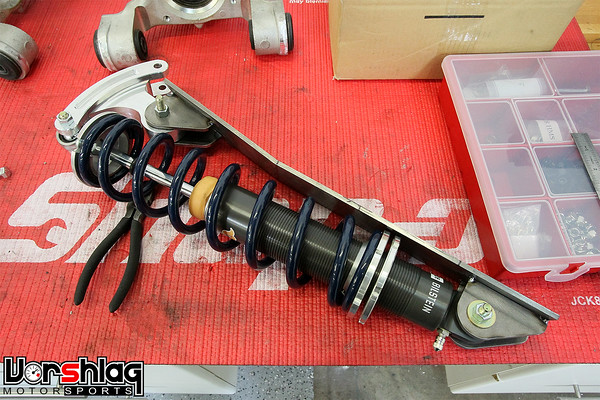
The front shock we had already built was used for the rear mock-ups and the length/stroke were pretty spot on for the rear, with the motion ratio of the bell crank and pushrod location on the rear control arm.
The rear control arms had double-shear pushrod mounting tabs added, then the pushrods were built, and the whole setup was then tested through the full range of suspension motion. Once that was confirmed the rear control arms were final welded.
We have fixed length mock-up rear shocks in place for the moment, but another pair of Bilstein ASN coilovers will be built to wrap up the suspension soon. Now we can at least check ride heights on the ground, start tire mock-up, and move forward on other systems with what we have in place.
The fuel filler neck will be relocated inside the trunk at the left corner, to leave room to load luggage for use on road trips. This car will not carry a spare tire, so some of the brackets that are used to hold the jack and temporary spare will be removed to add some much needed trunk volume.
The rear shock mounting is probably the craziest part of this swap, but again, it was the right solution for the constraints we had.
Engine Completion Work
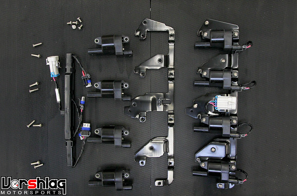
The built LS1 longblock that we have had in place for a while was finally dressed out with many missing intake and front accessory parts in recent months. First up was the coil packs and brackets, which were purchased, assembled and installed.
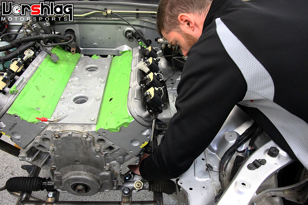
There are a number of various coil packs and coil pack sub-harness ends made for GenIII and GenIV LS series engines, but if you order the main engine harness correctly, it doesn't matter which you choose. We went with F-body brackets, sub-harness and coil packs. These bolt to 1999-02 Camaro LS1 valve covers, where I used button head stainless M6 bolts to hold them in place.
The LS2 intake manifold and throttle body were installed next. I explained in detail why we used an LS2 intake and throttle body on the Alpha Fr-S in THIS POST, which you can go back and read - because it also applies for this car. Basically the LS2 manifold has the same cathedral port shape as the LS1 heads on this motor, but it has the "short" drive-by-wire throttle body needed to clear the hood. If we would have used an LS3 motor the LS3 intake manifold and throttle body would have been the obvious choice. Cable operated throttle bodies are much longer and would not clear the hood line.
The front engine accessories and their mounting brackets were also finalized and installed. This car is being built without power steering, and we had originally mocked-up Pontiac G8 LS2 accessories - the same that the Alpha FR-S LS1 used - since that car has electric steering. These cars have very different engine bay shapes and widths, and on second look the 4th Gen F-body LS1 brackets, accessory layout and front drive pulleys were more appropriate, so we went that route instead.
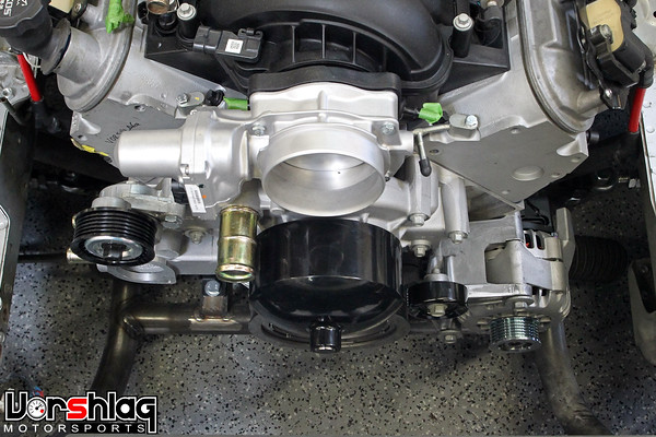
A new water pump, alternator, brackets, tensioner and idler pulley were procured, along with GM sourced hardware to attach all of this. I will show more details on the serpentine routing to bypass the power steering once the harmonic balancer/lower pulley is here (ordered weeks ago but on backorder), but the picture below shows the normal 4th gen LS1 belt routing - with the power steering pump in place. We have already changed the smooth idler pulley to a 6-ribbed pulley, which I installed with an 1/8" spacer to line up to the main belt "plane". Saw this on Yellow Bullet - those drag racers don't need no dang power steering.
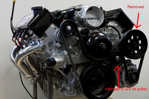
Long story here (back ordered part), but we're waiting on the correct SFI-rated front harmonic balancer and pulley for the 4th gen Camaro belt placement (there are 3 or 4 different belt placements for LS engines, front to back). The one we have installed now (shown below) was for the G8 accessory belt offset, which is about 1" too far back for the F-body accessories.
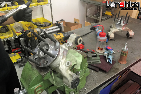
Rear Wheel Hubs Modified
The rear suspension uprights we used are a popular Ford Racing part made from a production Ford vehicle, and it is often use on Cobra Kit cars. These are made for Ford hubs, and we used the 31-spline 2003-04 Mustang Cobra hubs, which have a 5 x 4-1/2" bolt circle (5 x 114.3mm). This was a proven, durable, and readily available package. This Ford rear flange made perfect sense when the front suspension were going to be based around Mazda RX8 hubs/uprights/control arms. Ahh, the early days of this project were so simple...
Now we have Corvette front uprights and hubs, which use a GM 5 x 4-3/4" bolt circle (5 x 120.65mm), which doesn't match the rears. When we moved to the Corvette spindles we planned on modifying one end or the other so that the bolt patterns would match, and now was the time for this change.
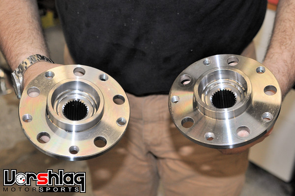
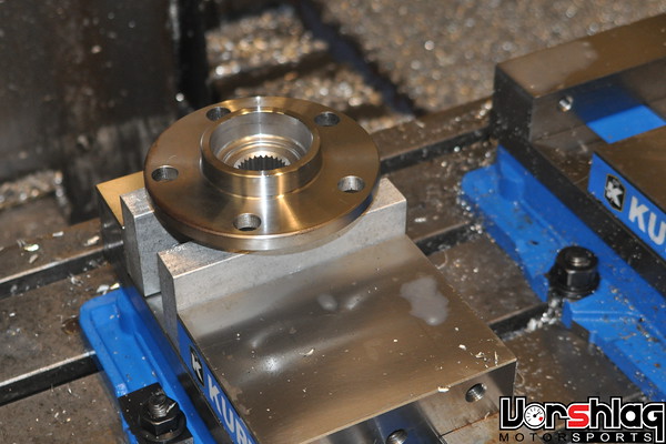
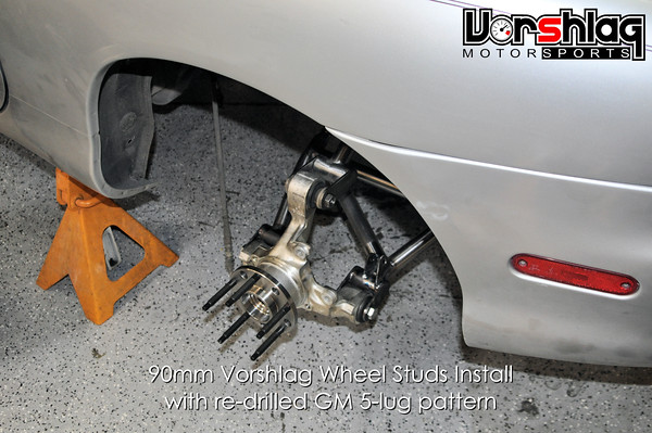
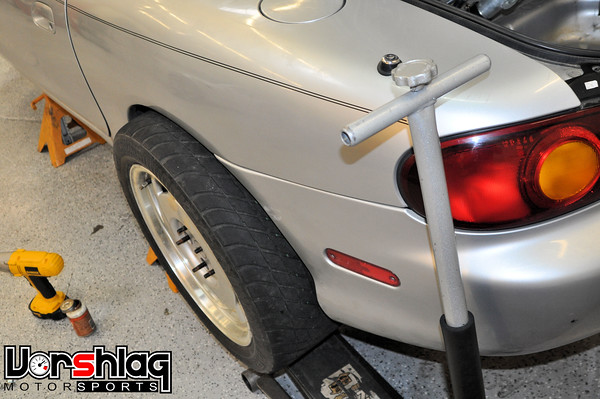
The guys removed the rear hubs from the uprights and Jason machined a custom set of soft jaws for the CNC mill to secure them in place. Then he installed the first hub, zero'd the machine on the hub center and face, programmed 5 new holes on the GM 5 x 4-3/4" bolt circle, and drilled them with the CNC. Instead of the pressed-in "splined" wheel studs that were used before (Ford still uses 1/2" stuff), we made these for screw-in wheel studs in a GM thread pitch and diameter...
Once out of the CNC vice, Jason tapped the newly drilled holes in both hubs for M12-1.5 thread pitch, then Olof installed Vorshlag 90mm wheel studs made for a BMW. We have these wheel studs made to our specs and sell thousands every year. GM and BMWs use the same stud and lug nut diameter and thread pitch (M12-1.5). Proven, tested, safe. Yes, they are long, but if we ever need to use spacers we have the room. This car can also be used in Gladiator races.
A drop of red Loctite is used when torquing these 90mm studs into the hubs, just like when installing them in BMWs. When installed correctly we can "zing" lug nuts off with an impact gun, with no issues. The completed hubs were then installed back into the rear uprights and the assemblies went back into the rear suspension. Now its time to mock up some GM bolt pattern wheels!
continued below

I will go into more details on this rear suspension once we have done some road testing, but so far I'm happy with the results. The bell cranks were CNC machined in custom fixtures over 3 operations to make the completed bits. Radial ball bearings were installed for the pivots and rod-ends are attached at each end of the bell crank - one to the pushrod and the other to the shock.

The front shock we had already built was used for the rear mock-ups and the length/stroke were pretty spot on for the rear, with the motion ratio of the bell crank and pushrod location on the rear control arm.

The rear control arms had double-shear pushrod mounting tabs added, then the pushrods were built, and the whole setup was then tested through the full range of suspension motion. Once that was confirmed the rear control arms were final welded.

We have fixed length mock-up rear shocks in place for the moment, but another pair of Bilstein ASN coilovers will be built to wrap up the suspension soon. Now we can at least check ride heights on the ground, start tire mock-up, and move forward on other systems with what we have in place.

The fuel filler neck will be relocated inside the trunk at the left corner, to leave room to load luggage for use on road trips. This car will not carry a spare tire, so some of the brackets that are used to hold the jack and temporary spare will be removed to add some much needed trunk volume.

The rear shock mounting is probably the craziest part of this swap, but again, it was the right solution for the constraints we had.
Engine Completion Work
The built LS1 longblock that we have had in place for a while was finally dressed out with many missing intake and front accessory parts in recent months. First up was the coil packs and brackets, which were purchased, assembled and installed.

There are a number of various coil packs and coil pack sub-harness ends made for GenIII and GenIV LS series engines, but if you order the main engine harness correctly, it doesn't matter which you choose. We went with F-body brackets, sub-harness and coil packs. These bolt to 1999-02 Camaro LS1 valve covers, where I used button head stainless M6 bolts to hold them in place.

The LS2 intake manifold and throttle body were installed next. I explained in detail why we used an LS2 intake and throttle body on the Alpha Fr-S in THIS POST, which you can go back and read - because it also applies for this car. Basically the LS2 manifold has the same cathedral port shape as the LS1 heads on this motor, but it has the "short" drive-by-wire throttle body needed to clear the hood. If we would have used an LS3 motor the LS3 intake manifold and throttle body would have been the obvious choice. Cable operated throttle bodies are much longer and would not clear the hood line.

The front engine accessories and their mounting brackets were also finalized and installed. This car is being built without power steering, and we had originally mocked-up Pontiac G8 LS2 accessories - the same that the Alpha FR-S LS1 used - since that car has electric steering. These cars have very different engine bay shapes and widths, and on second look the 4th Gen F-body LS1 brackets, accessory layout and front drive pulleys were more appropriate, so we went that route instead.

A new water pump, alternator, brackets, tensioner and idler pulley were procured, along with GM sourced hardware to attach all of this. I will show more details on the serpentine routing to bypass the power steering once the harmonic balancer/lower pulley is here (ordered weeks ago but on backorder), but the picture below shows the normal 4th gen LS1 belt routing - with the power steering pump in place. We have already changed the smooth idler pulley to a 6-ribbed pulley, which I installed with an 1/8" spacer to line up to the main belt "plane". Saw this on Yellow Bullet - those drag racers don't need no dang power steering.
Long story here (back ordered part), but we're waiting on the correct SFI-rated front harmonic balancer and pulley for the 4th gen Camaro belt placement (there are 3 or 4 different belt placements for LS engines, front to back). The one we have installed now (shown below) was for the G8 accessory belt offset, which is about 1" too far back for the F-body accessories.

Rear Wheel Hubs Modified
The rear suspension uprights we used are a popular Ford Racing part made from a production Ford vehicle, and it is often use on Cobra Kit cars. These are made for Ford hubs, and we used the 31-spline 2003-04 Mustang Cobra hubs, which have a 5 x 4-1/2" bolt circle (5 x 114.3mm). This was a proven, durable, and readily available package. This Ford rear flange made perfect sense when the front suspension were going to be based around Mazda RX8 hubs/uprights/control arms. Ahh, the early days of this project were so simple...

Now we have Corvette front uprights and hubs, which use a GM 5 x 4-3/4" bolt circle (5 x 120.65mm), which doesn't match the rears. When we moved to the Corvette spindles we planned on modifying one end or the other so that the bolt patterns would match, and now was the time for this change.

The guys removed the rear hubs from the uprights and Jason machined a custom set of soft jaws for the CNC mill to secure them in place. Then he installed the first hub, zero'd the machine on the hub center and face, programmed 5 new holes on the GM 5 x 4-3/4" bolt circle, and drilled them with the CNC. Instead of the pressed-in "splined" wheel studs that were used before (Ford still uses 1/2" stuff), we made these for screw-in wheel studs in a GM thread pitch and diameter...

Once out of the CNC vice, Jason tapped the newly drilled holes in both hubs for M12-1.5 thread pitch, then Olof installed Vorshlag 90mm wheel studs made for a BMW. We have these wheel studs made to our specs and sell thousands every year. GM and BMWs use the same stud and lug nut diameter and thread pitch (M12-1.5). Proven, tested, safe. Yes, they are long, but if we ever need to use spacers we have the room. This car can also be used in Gladiator races.

A drop of red Loctite is used when torquing these 90mm studs into the hubs, just like when installing them in BMWs. When installed correctly we can "zing" lug nuts off with an impact gun, with no issues. The completed hubs were then installed back into the rear uprights and the assemblies went back into the rear suspension. Now its time to mock up some GM bolt pattern wheels!

continued below
11-12-2015, 09:14 AM
#42
continued from above
Ugly. I first tested with some C4 Corvette 17x9.5" wheels and 275/40/17 tires (the OEM wheels that were on my 1992 Corvette when I bought it). These are much taller tires, the wheels had the wrong offsets, and were not useful in mock-up at all. We looked around the shop and then found the perfect set to test with - which would allow us to drop the car on the ground for the first time in a LONG time...
Down on the Wheels + Flare Mock-up
This was a big step just a few weeks ago, with the Miata placed down onto some decently sized wheels and tires with the new custom front and rear suspension setups. Damn happy that this car now rolls...
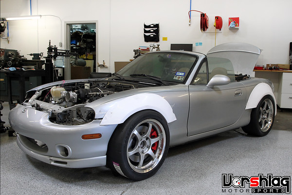
This time Ryan installed the race wheels and tires from my NASA TTC classed 1992 Corvette race car. Due to class restrictions we run that car on a 245mm tire (Hoosier R7), but its a BIG 245, with 9.7" of tread width. These tires are mounted to some lightweight SSR 17x9.5" wheels with a GM 5-lug bolt pattern. The mock-up tires (245/40/17 Hoosier) are still too narrow for this car's power level, but they were 24.3" tall and somewhat similar in width to what we will end up with (285mm on 18x10" wheel).
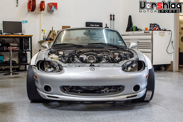
The Miata's owner provided this wide body kit, which is a fiberglass reproduction of a popular NB flare kit. It has 4 flares, a new composite nose (not yet fitted) made for NB2 headlights, and side skirts to tie it all together.
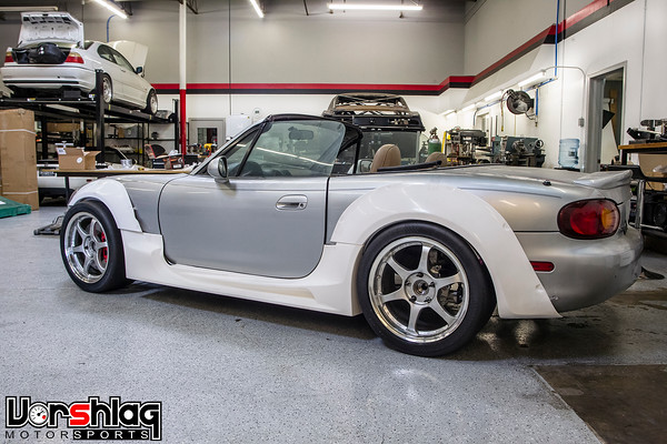
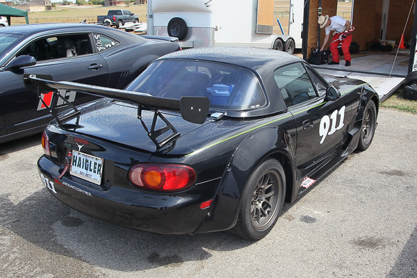
The styling of this kit looks odd in these mock-ups, but once painted and "fitted" they work fairly well. The race car shown below has the same kit. We saw this at a recent track day at MSR-Cresson and it used 275/35/15 Hoosier race tires on 15x10" wheels, which is super short (23.0" tall) and easy to fit onto these cars with this body kit.
Ultimately we're still shooting for a 285/30/18 tire and an 18x10" wheel. Why not go with the proven 275mm 15" Hoosier that fits this body kit? Two reasons. First its narrower, but more importantly there are ZERO street tire choices in this size or anything close to it. There is a Hoosier race tire and... nothing else.
The 285/30/18 tire shown above is fairly popular for racing use and gives the owner over a dozen choices in street tires + several DOT-R race rubber choices as well. We will have to modify the front frame horns for the taller 24.9" diameter tire, to have adequate bump travel, but we always knew that. This 285/30/18 size is really the best option: super short for the width and wheel diameter it has, with a lot of tire choices.
And yes, the images above shows the Miata and the 17x9.5" wheels with some serious "poke" past the front flares. The front and rear tracks were measured identical here, but the body kit's flares have much wider rear flares than front flares. Still, we managed to address this issue earlier this week, by adding some much needed front negative camber. See below.
Front Suspension Progress
The initial suspension measurements and mock-ups were done "in the air" but once the car was sitting on all 4 wheels and tires at ride height, it was obvious the front needed a tweak to the upper control arms to get the static camber settings in the right range.
These were the last arms to be final welded, and were only tacked in place. It was assumed that there might be some adjustment once at ride height. The upper arms were removed, shortened, mocked up then final welded earlier this week.
The car now has -3� camber front camber and adjustments to go up and down from that range. Side benefit - which we knew would happen - is that the front tires now fit under the flares much better.
Next we will measure the existing 17x9.5" wheels and look at how far we can go inboard with an 18x10". Then we will order up some Forgestar custom 1-piece wheels in this size and add some 285/30/18 Hoosier A6 tires that were acquired for mock-up use.
The Miata will eventually be built on 285/30/18 tires from the new "magic" 200 treadwear sticky street tire options... but instead of buying those NOW, it makes more sense to wait until closer to completion, as tire options and supplies change every quarter. Who knows what uber-tires will be introduced in a few months for 200 treadware tires? There are Tire Wars in process!
What's Next?
We have the supplies on hand for making custom headers, supplied by Magnaflow. These 1.75" primary mandrel bends, 3" collectors and LS1 flanges will be used to make the headers soon.
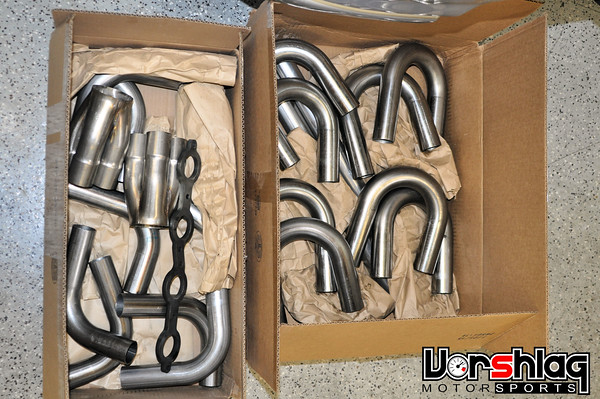
The driveshaft has to be built first, so the headers and exhaust can route around that. Some Miata "rail stiffeners" and a "butterfly brace" will be added first, to make sure everything routes nicely together - braces, driveshaft and exhaust.
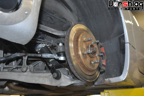
Rear brakes are also being address very shortly. C5 Corvette rear brake rotors (see above) were ordered and should be here any day. We already have C5 rear calipers and pads and plan to make brackets to mount these to the rear uprights that are in place. Then we can move onto plumbing the brake and clutch hydraulics, have the wiring harness built, and more.
More soon,
Ugly. I first tested with some C4 Corvette 17x9.5" wheels and 275/40/17 tires (the OEM wheels that were on my 1992 Corvette when I bought it). These are much taller tires, the wheels had the wrong offsets, and were not useful in mock-up at all. We looked around the shop and then found the perfect set to test with - which would allow us to drop the car on the ground for the first time in a LONG time...

Down on the Wheels + Flare Mock-up
This was a big step just a few weeks ago, with the Miata placed down onto some decently sized wheels and tires with the new custom front and rear suspension setups. Damn happy that this car now rolls...

This time Ryan installed the race wheels and tires from my NASA TTC classed 1992 Corvette race car. Due to class restrictions we run that car on a 245mm tire (Hoosier R7), but its a BIG 245, with 9.7" of tread width. These tires are mounted to some lightweight SSR 17x9.5" wheels with a GM 5-lug bolt pattern. The mock-up tires (245/40/17 Hoosier) are still too narrow for this car's power level, but they were 24.3" tall and somewhat similar in width to what we will end up with (285mm on 18x10" wheel).

The Miata's owner provided this wide body kit, which is a fiberglass reproduction of a popular NB flare kit. It has 4 flares, a new composite nose (not yet fitted) made for NB2 headlights, and side skirts to tie it all together.

The styling of this kit looks odd in these mock-ups, but once painted and "fitted" they work fairly well. The race car shown below has the same kit. We saw this at a recent track day at MSR-Cresson and it used 275/35/15 Hoosier race tires on 15x10" wheels, which is super short (23.0" tall) and easy to fit onto these cars with this body kit.

Ultimately we're still shooting for a 285/30/18 tire and an 18x10" wheel. Why not go with the proven 275mm 15" Hoosier that fits this body kit? Two reasons. First its narrower, but more importantly there are ZERO street tire choices in this size or anything close to it. There is a Hoosier race tire and... nothing else.

The 285/30/18 tire shown above is fairly popular for racing use and gives the owner over a dozen choices in street tires + several DOT-R race rubber choices as well. We will have to modify the front frame horns for the taller 24.9" diameter tire, to have adequate bump travel, but we always knew that. This 285/30/18 size is really the best option: super short for the width and wheel diameter it has, with a lot of tire choices.

And yes, the images above shows the Miata and the 17x9.5" wheels with some serious "poke" past the front flares. The front and rear tracks were measured identical here, but the body kit's flares have much wider rear flares than front flares. Still, we managed to address this issue earlier this week, by adding some much needed front negative camber. See below.
Front Suspension Progress
The initial suspension measurements and mock-ups were done "in the air" but once the car was sitting on all 4 wheels and tires at ride height, it was obvious the front needed a tweak to the upper control arms to get the static camber settings in the right range.

These were the last arms to be final welded, and were only tacked in place. It was assumed that there might be some adjustment once at ride height. The upper arms were removed, shortened, mocked up then final welded earlier this week.

The car now has -3� camber front camber and adjustments to go up and down from that range. Side benefit - which we knew would happen - is that the front tires now fit under the flares much better.

Next we will measure the existing 17x9.5" wheels and look at how far we can go inboard with an 18x10". Then we will order up some Forgestar custom 1-piece wheels in this size and add some 285/30/18 Hoosier A6 tires that were acquired for mock-up use.

The Miata will eventually be built on 285/30/18 tires from the new "magic" 200 treadwear sticky street tire options... but instead of buying those NOW, it makes more sense to wait until closer to completion, as tire options and supplies change every quarter. Who knows what uber-tires will be introduced in a few months for 200 treadware tires? There are Tire Wars in process!
What's Next?
We have the supplies on hand for making custom headers, supplied by Magnaflow. These 1.75" primary mandrel bends, 3" collectors and LS1 flanges will be used to make the headers soon.

The driveshaft has to be built first, so the headers and exhaust can route around that. Some Miata "rail stiffeners" and a "butterfly brace" will be added first, to make sure everything routes nicely together - braces, driveshaft and exhaust.

Rear brakes are also being address very shortly. C5 Corvette rear brake rotors (see above) were ordered and should be here any day. We already have C5 rear calipers and pads and plan to make brackets to mount these to the rear uprights that are in place. Then we can move onto plumbing the brake and clutch hydraulics, have the wiring harness built, and more.
More soon,
The following users liked this post:
charchri4 (11-12-2015)
 04-29-2016, 10:58 AM
#44
Project Update for April 28, 2016: It has been another long break since my last update on this Alpha Miata LS1 swap build thread, but we have made a ton of progress since then. We have so much work to cover that its going to take a number of installments, but I've been buried with work and am behind on the build thread. One thing I wanted to point out - this is not going to be made into a kit, because it would be so costly as to be unattractive to almost everyone. We cut that goal shortly after my last post and that sped up this build considerably.
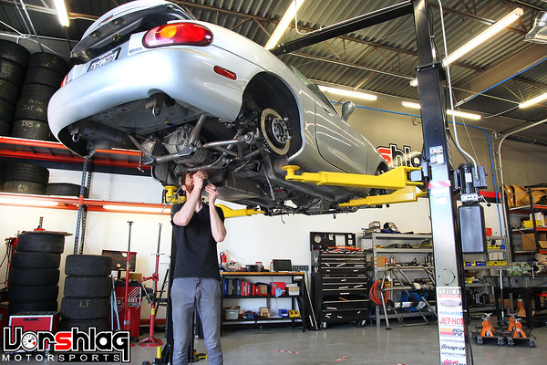
In the next handful of updates we will cover the custom exhaust headers, the custom DSS rear axles, custom driveshaft, we switched transmissions (again!), made a customized shifter and trans tunnel cover, installed the Air Con, ordered and installed the wiring harness, removed the fuel tank and started plumbing that system, custom built a radiator and installed that, built all of the cooling hoses, mounted a remote coolant reservoir, mounted the C5 rear brake calipers, built the remaining two shocks and installed the springs, added a C6 electronic throttle pedal, modified the booster to mount a C5 brake master cylinder, made an adapter to fit a Tilton clutch master cylinder, and dug into the wiring of the motor and gauges. We also spec'd 18x10" Forgestar wheels, got those in, and mounted 285/30/18 Hoosiers (tires only being used for mock-up and fender mods). Whew! Lots to cover, so let's get going with the first update.
MORE TRANSMISSION FOLLIES
One of the things that happened right after my November post was a change of transmissions... This project has been a real ball buster with respect to the transmission! The initial desire on this swap was to avoid the transmission tunnel mods needed in other V8 swap kits. This seemed like an extra burden that would prevent DIY mechanics from doing this swap at home, and in fact that has been a common complaint from many V8 Miata swappers. Funny enough, none of this matters now that we blew off the "kit" plans.
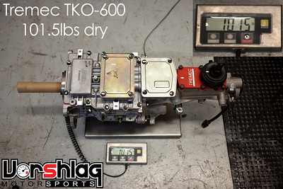
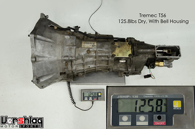
Still, hacking up the tunnel seemed unnecessary to me if we were willing to make a custom front crossmember - which we did, and that added LOTS of room to move the engine lower than the kits out there. Modding the tunnel would mean removing the entire dash and interior, cut and slice the floor pan, weld in some new sheet metal, then stitch weld that all back together to clear the T56 - as is done with the other V8 Miata kits. We thought a move to the Tremec TKO 5 speed would be beneficial and tried that... but ran into some packaging difficulties. Then we tested a 4th gen Camaro T56, and that worked, so we built the kit around that.
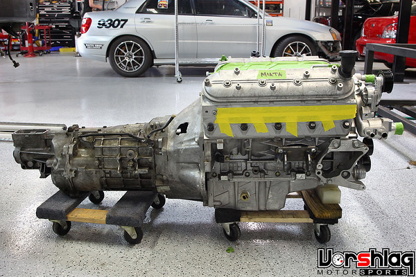
4th gen F-body T56 and bellhousing attached to the final LS1 engine
After we had the engine mounts and crossmember developed around the 4th gen T56, we ordered a brand new T56 Magnum. Now this term "Magnum" is bandied about freely, but there are a lot of definitions of a "T56 Magnum". This is where a mistake happened... and damn it, I know better.
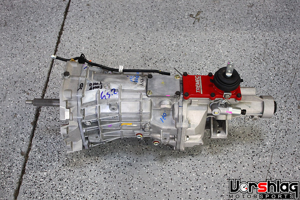
This is the real T56 Magnum, brand new and available from Tremec for T56 applications...?
New T56 Magnums are the unit shown above, available from Tremec, which has a different front to back length and different shifter location than a 4th Gen F-body OEM T56 (1998-2002). Those differences are big but are NOT clearly shown in their catalogs. These are images of the two T56 models and they don't even measure them the same way.
The T56 Magnum version is stronger and more readily available - the 4th gen F-body T56 has been out of production for going on 7-8 years. We tend to use T56 Magnums in our BMW V8 swaps, but it only requires a driveshaft change. Otherwise you end up hunting in junkyards for F-body length T56 units, but they are so old by now they all have to be rebuilt... in the end you spend more rebuilding an old T56 than buying a new T56 Magnum.
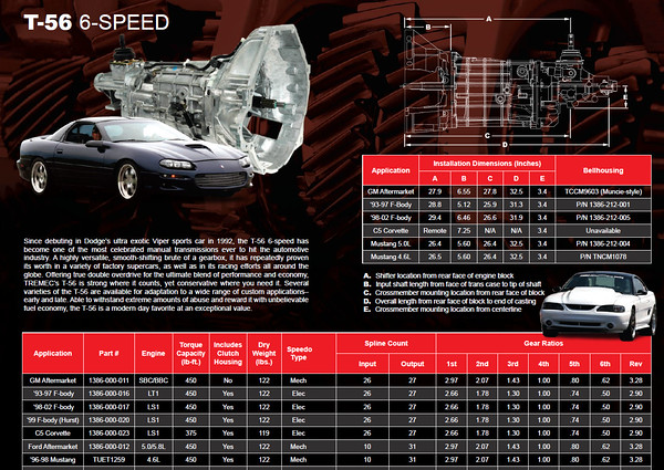
There are many shops, however, who sell upgraded F-body T56 transmissions as a "T56 Magnum" edition. They are dimensionally different than brand new T56 Magnums made by Tremec... and often have different input or output shaft lengths and spline counts. We get customers ordering the wrong BMW V8 swap driveshafts because of this "Magnum" name being mis-used.
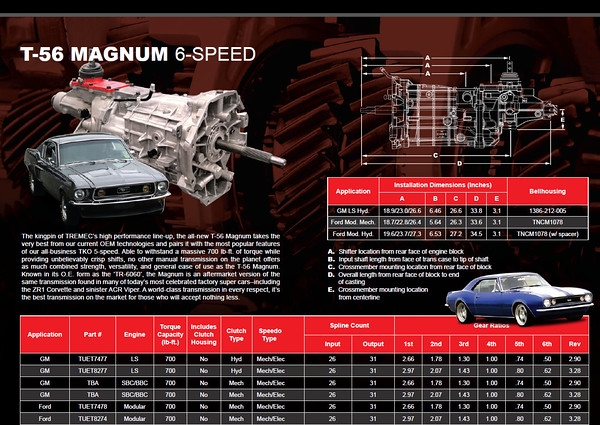
What these two Tremec catalog charts don't show is that the location of the shifter is very different between the F-body T56 and the T56 Magnum. Notice how "A" is measured differently in the Tremec catalog? Well this is a real mess that Tremec should fix in their literature, but they stopped selling the F-body T56 about 6-7 years ago and its not been listed in their catalog since 2009.
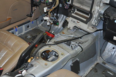
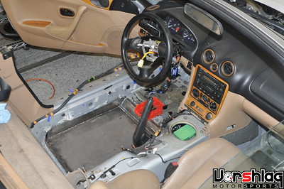
Left: The T56 Magnum shifter location is too far forward (inside the dash!). Right: 4th gen T56 is much better!
After we received the new T56 Magnum our crew installed it into the car. I looked in the stock shifter hole (above left) and saw that it was waaaay too far forward. Not good. I admit to uttering a few choice words. The T56 Magnum has a shifter location that is about 3" farther forward compared to the 4th gen. Again, I had figured this out in 2008 but somehow forgot this key piece of knowledge. In the BMW V8 swaps it never mattered much (there was plenty of wiggle room in the tunnel/console). On the Miata the Magnum shifter base is inside the center stack of the dashboard, so I had to punt.
I took a used 4th gen T56 mock-up transmission I had in the shop and asked our friends at Dedrichs Motorsports to completely rebuild it.
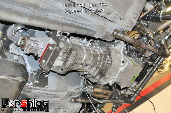
Now this T56 brand new, upgraded, and most importantly - has the shifter in the right spot! It has a new input shaft, main gear cluster, synchros, and all new bearings and seals. Even most of the gears had to be replaced. Using the T56 Magnum with the as-built shifter location would just not work - we would have had to move the engine back about 3 inches, which would require serious firewall and tunnel mods that nobody was keen to do.
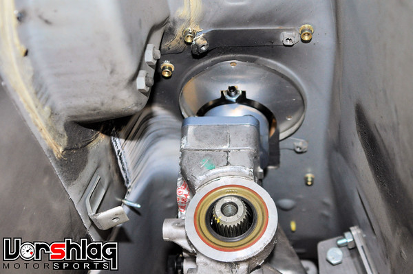
Oh well, live and learn. This one is 100% on me and I had to eat the cost difference between the two T56s (and some labor hours), but we will use the T56 Magnum on another V8 swap project we will tackle soon. At this point we could at least move forward with the custom exhaust header development, driveshaft construction, and exhaust system layout. The T56 debacle held us up for a couple of months but Joe at Dedrich's Motorsports went through our old T56 and made it a new monster inside.
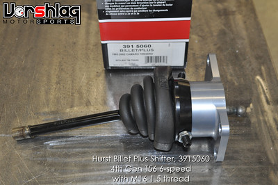
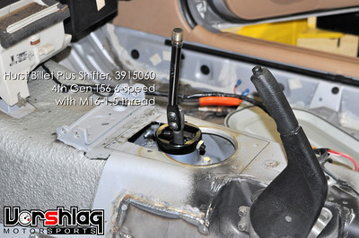
I'm skipping ahead a couple of months here. We purchased the Hurst 6-speed for the 1998-02 Camaro T56 and put it in the car, knowing it would likely need to be modified at the base, handle and such. The Miata trans tunnel opening had to be notched a bit on the leading edge, too.
continued below

In the next handful of updates we will cover the custom exhaust headers, the custom DSS rear axles, custom driveshaft, we switched transmissions (again!), made a customized shifter and trans tunnel cover, installed the Air Con, ordered and installed the wiring harness, removed the fuel tank and started plumbing that system, custom built a radiator and installed that, built all of the cooling hoses, mounted a remote coolant reservoir, mounted the C5 rear brake calipers, built the remaining two shocks and installed the springs, added a C6 electronic throttle pedal, modified the booster to mount a C5 brake master cylinder, made an adapter to fit a Tilton clutch master cylinder, and dug into the wiring of the motor and gauges. We also spec'd 18x10" Forgestar wheels, got those in, and mounted 285/30/18 Hoosiers (tires only being used for mock-up and fender mods). Whew! Lots to cover, so let's get going with the first update.
MORE TRANSMISSION FOLLIES
One of the things that happened right after my November post was a change of transmissions... This project has been a real ball buster with respect to the transmission! The initial desire on this swap was to avoid the transmission tunnel mods needed in other V8 swap kits. This seemed like an extra burden that would prevent DIY mechanics from doing this swap at home, and in fact that has been a common complaint from many V8 Miata swappers. Funny enough, none of this matters now that we blew off the "kit" plans.


Still, hacking up the tunnel seemed unnecessary to me if we were willing to make a custom front crossmember - which we did, and that added LOTS of room to move the engine lower than the kits out there. Modding the tunnel would mean removing the entire dash and interior, cut and slice the floor pan, weld in some new sheet metal, then stitch weld that all back together to clear the T56 - as is done with the other V8 Miata kits. We thought a move to the Tremec TKO 5 speed would be beneficial and tried that... but ran into some packaging difficulties. Then we tested a 4th gen Camaro T56, and that worked, so we built the kit around that.
4th gen F-body T56 and bellhousing attached to the final LS1 engine
After we had the engine mounts and crossmember developed around the 4th gen T56, we ordered a brand new T56 Magnum. Now this term "Magnum" is bandied about freely, but there are a lot of definitions of a "T56 Magnum". This is where a mistake happened... and damn it, I know better.

This is the real T56 Magnum, brand new and available from Tremec for T56 applications...?
New T56 Magnums are the unit shown above, available from Tremec, which has a different front to back length and different shifter location than a 4th Gen F-body OEM T56 (1998-2002). Those differences are big but are NOT clearly shown in their catalogs. These are images of the two T56 models and they don't even measure them the same way.
The T56 Magnum version is stronger and more readily available - the 4th gen F-body T56 has been out of production for going on 7-8 years. We tend to use T56 Magnums in our BMW V8 swaps, but it only requires a driveshaft change. Otherwise you end up hunting in junkyards for F-body length T56 units, but they are so old by now they all have to be rebuilt... in the end you spend more rebuilding an old T56 than buying a new T56 Magnum.

There are many shops, however, who sell upgraded F-body T56 transmissions as a "T56 Magnum" edition. They are dimensionally different than brand new T56 Magnums made by Tremec... and often have different input or output shaft lengths and spline counts. We get customers ordering the wrong BMW V8 swap driveshafts because of this "Magnum" name being mis-used.

What these two Tremec catalog charts don't show is that the location of the shifter is very different between the F-body T56 and the T56 Magnum. Notice how "A" is measured differently in the Tremec catalog? Well this is a real mess that Tremec should fix in their literature, but they stopped selling the F-body T56 about 6-7 years ago and its not been listed in their catalog since 2009.


Left: The T56 Magnum shifter location is too far forward (inside the dash!). Right: 4th gen T56 is much better!
After we received the new T56 Magnum our crew installed it into the car. I looked in the stock shifter hole (above left) and saw that it was waaaay too far forward. Not good. I admit to uttering a few choice words. The T56 Magnum has a shifter location that is about 3" farther forward compared to the 4th gen. Again, I had figured this out in 2008 but somehow forgot this key piece of knowledge. In the BMW V8 swaps it never mattered much (there was plenty of wiggle room in the tunnel/console). On the Miata the Magnum shifter base is inside the center stack of the dashboard, so I had to punt.
I took a used 4th gen T56 mock-up transmission I had in the shop and asked our friends at Dedrichs Motorsports to completely rebuild it.

Now this T56 brand new, upgraded, and most importantly - has the shifter in the right spot! It has a new input shaft, main gear cluster, synchros, and all new bearings and seals. Even most of the gears had to be replaced. Using the T56 Magnum with the as-built shifter location would just not work - we would have had to move the engine back about 3 inches, which would require serious firewall and tunnel mods that nobody was keen to do.

Oh well, live and learn. This one is 100% on me and I had to eat the cost difference between the two T56s (and some labor hours), but we will use the T56 Magnum on another V8 swap project we will tackle soon. At this point we could at least move forward with the custom exhaust header development, driveshaft construction, and exhaust system layout. The T56 debacle held us up for a couple of months but Joe at Dedrich's Motorsports went through our old T56 and made it a new monster inside.


I'm skipping ahead a couple of months here. We purchased the Hurst 6-speed for the 1998-02 Camaro T56 and put it in the car, knowing it would likely need to be modified at the base, handle and such. The Miata trans tunnel opening had to be notched a bit on the leading edge, too.
continued below
04-29-2016, 11:01 AM
#45
continued from above
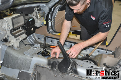
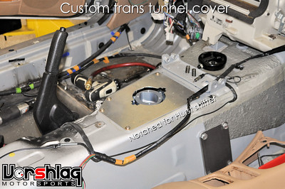
To cover up the now over-sized transmission tunnel hole Ryan made a piece of aluminum plate to fit, which bolts to the tunnel and is notched to clear the Hurst shifter and adjustable 3/4 shift stops.
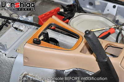
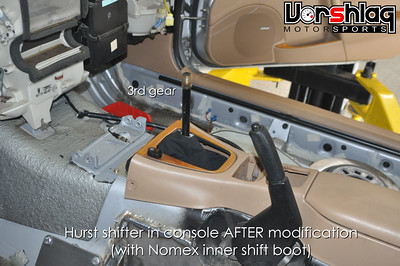
The shift handle was still too far forward so Ryan modified both the base and the handle to offset them rearward and angled back towards the driver. This made the shifter fall closer to hand and eased the interference with the stock center console opening.
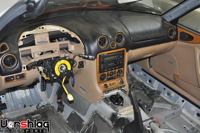
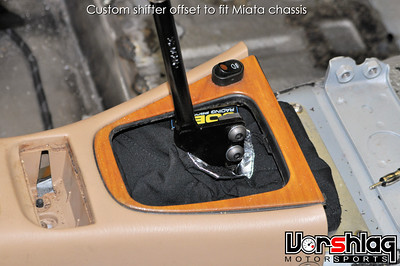
We also ordered a Joe's Racing fire proof/Nomex shift boot and frame, which we install on virtually any car we build with a V8 swap. This helps seal up any opening in the tunnel, to make that opening fire proof and to reduce heat and noise transferred to the cabin. These come with an aluminum frame that has snaps built around the edge and the Nomex boot snaps over that. In the above right picture I pulled the shift boot down over the modified handle for the picture, but it slips up and has a velcro connection to close the gap around the shaft.
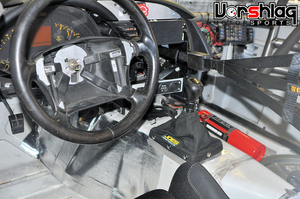
Here's a picture of the same Nomex shift boot added to my C4 Corvette recently, as well as some thermal / radiant barrier near my leg (no interior to shield heat from exhaust/trans). It can be used to completely replace a factory boot, or like we did here, go over the factory rubber tunnel seal. In the Miata it is under the factory leather shift boot. Regardless - its a GOOD IDEA to add one of these ~$90 fire proof shift boots to any race car or any car with a modified tunnel opening.
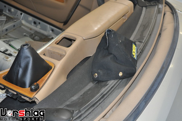
The original factory shift boot was old and torn so a brand new Mazda sourced leather shift boot was purchased. This is going to be street driven and have a full interior, of course. This Nomex shift boot will all be hidden under the leather boot. Other than that, the transmission just needs a shift **** and some fluid, plus the reverse lockout wiring and speedometer connection.

Once the transmission was in the car and finally "locked down" the driveshaft, so that could be spec'd and ordered. We got it about a week later and installed that.
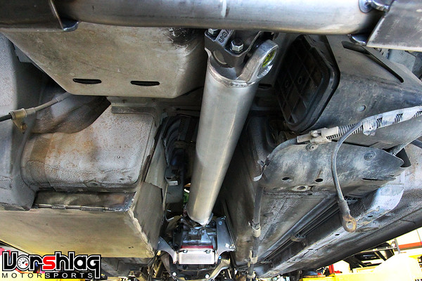
That was installed for fitment checks and exhaust routing, and it looked perfect. Big 3.0" diameter aluminum unit rated for 600 hp, so it should be fine with 475 whp.
BRAKE WORK
Shortly after my last post the C5 Corvette rear rotors arrived. These are StopTech/Centric Premium blanks (the "Premium" version gets you powder coated centers instead of raw cast iron - no rusting) which are 12.0" in diameter and 1.0" thick, which are the same rear brakes on all C5 generation Corvettes (1997-2004), from the base models to the Z06.
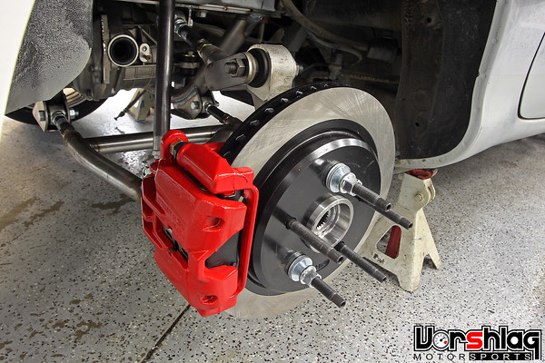
When we had the rotors in hand and the rear hubs re-drilled for the GM bolt pattern Ryan mocked up the C5 rear calipers and brackets (above). Making the actual bracket to mount these correctly didn't happen until several months later. Initially we were going to measure then CNC machine these on the mill, but our machines and engineer are so tied up making suspension products it fell onto Ryan to fabricate these in April.
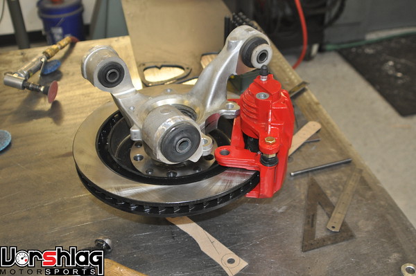
First the calipers, pads and slider brackets were mocked up on the rotor and aluminum upright, on the fab table.
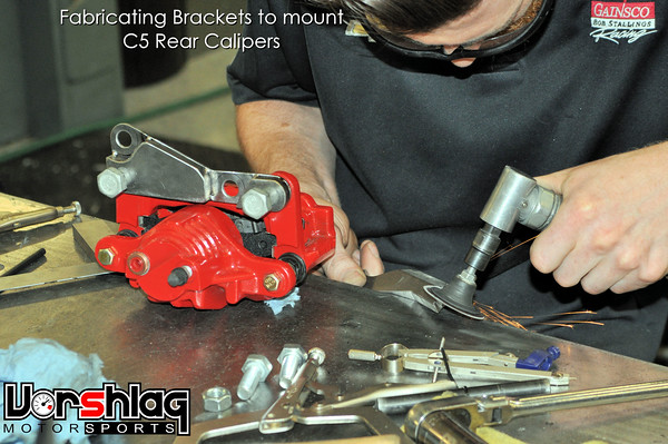
Then came hours of measuring, cutting, welding and juggling of thicknesses to get the calipers mounted in the right radial and lateral positions relative to the rotor.
Other than the flex lines to connect to the rear hard lines, this C5 rear caliper / C5 rotor / 03-04 Cobra rear hub swap is done.
Since the front brakes are C5 and the rear brakes are C5, I had the obvious idea of ... using a C5 Corvette brake master cylinder to actuate the calipers. Kind of a no-brainer, right? I asked the guys to yank the Miata brake master off and I did some measuring...
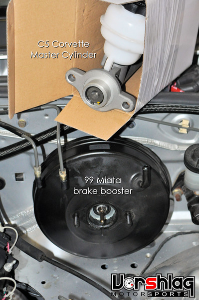
We had a C5 in the shop and the stock C5 master looked dang close. So I ordered a C5 master cylinder as a test...
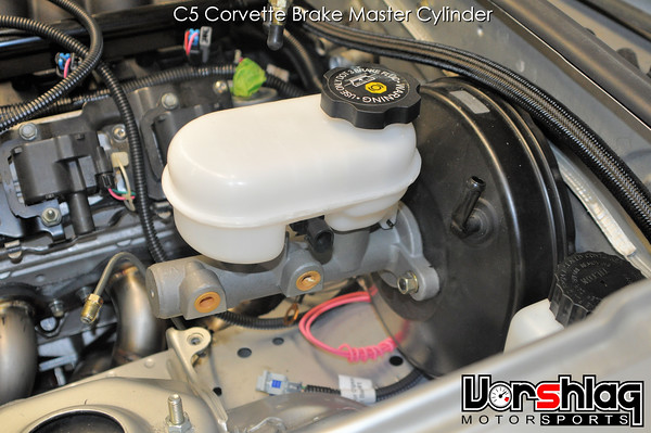
Sometimes I'd rather be lucky than good! All it took was shortening the "stem" from the booster/pedal and just a kiss of hole enlargement on the C5 master cylinder mounting flange and it slid right into the Miata booster. Win!
Now that the brake master was handled Ryan tackled the task of adapting a Tilton master cylinder to the firewall for the clutch hydraulics. Yea, its not "Brake system" but its pretty close, so roll with it.
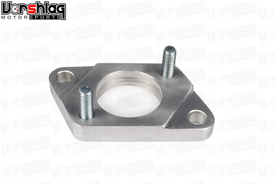
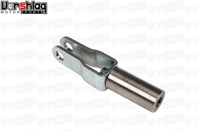
Just like on the FR-S LS1 swap, Ryan made a billet aluminum adapter to go from the firewall bolt spacing of the Miata clutch master to the Tilton mounting flange. He made it so fast I never got a picture, so the pics of FR-S parts above will have to do (similar in design).
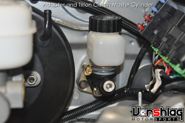
Once the firewall adapter and pushrod changes were made the Tilton clutch master cylinder was functional. This will change the hydraulic ratio of the clutch circuit using a larger diameter master cylinder that we've used in the past and know works with the clutch we're using.
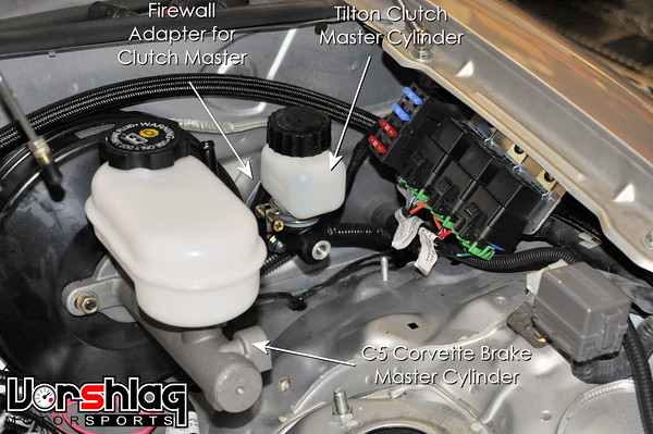
That's the firewall line-up with the Tilton clutch master, firewall adapter, the C5 brake master. There's wiring and fuel system plumbing shown, but I wanted to keep this post short and sweet so I will cover that and MUCH more next time.
Thanks for reading,


To cover up the now over-sized transmission tunnel hole Ryan made a piece of aluminum plate to fit, which bolts to the tunnel and is notched to clear the Hurst shifter and adjustable 3/4 shift stops.


The shift handle was still too far forward so Ryan modified both the base and the handle to offset them rearward and angled back towards the driver. This made the shifter fall closer to hand and eased the interference with the stock center console opening.


We also ordered a Joe's Racing fire proof/Nomex shift boot and frame, which we install on virtually any car we build with a V8 swap. This helps seal up any opening in the tunnel, to make that opening fire proof and to reduce heat and noise transferred to the cabin. These come with an aluminum frame that has snaps built around the edge and the Nomex boot snaps over that. In the above right picture I pulled the shift boot down over the modified handle for the picture, but it slips up and has a velcro connection to close the gap around the shaft.

Here's a picture of the same Nomex shift boot added to my C4 Corvette recently, as well as some thermal / radiant barrier near my leg (no interior to shield heat from exhaust/trans). It can be used to completely replace a factory boot, or like we did here, go over the factory rubber tunnel seal. In the Miata it is under the factory leather shift boot. Regardless - its a GOOD IDEA to add one of these ~$90 fire proof shift boots to any race car or any car with a modified tunnel opening.

The original factory shift boot was old and torn so a brand new Mazda sourced leather shift boot was purchased. This is going to be street driven and have a full interior, of course. This Nomex shift boot will all be hidden under the leather boot. Other than that, the transmission just needs a shift **** and some fluid, plus the reverse lockout wiring and speedometer connection.

Once the transmission was in the car and finally "locked down" the driveshaft, so that could be spec'd and ordered. We got it about a week later and installed that.

That was installed for fitment checks and exhaust routing, and it looked perfect. Big 3.0" diameter aluminum unit rated for 600 hp, so it should be fine with 475 whp.
BRAKE WORK
Shortly after my last post the C5 Corvette rear rotors arrived. These are StopTech/Centric Premium blanks (the "Premium" version gets you powder coated centers instead of raw cast iron - no rusting) which are 12.0" in diameter and 1.0" thick, which are the same rear brakes on all C5 generation Corvettes (1997-2004), from the base models to the Z06.

When we had the rotors in hand and the rear hubs re-drilled for the GM bolt pattern Ryan mocked up the C5 rear calipers and brackets (above). Making the actual bracket to mount these correctly didn't happen until several months later. Initially we were going to measure then CNC machine these on the mill, but our machines and engineer are so tied up making suspension products it fell onto Ryan to fabricate these in April.

First the calipers, pads and slider brackets were mocked up on the rotor and aluminum upright, on the fab table.

Then came hours of measuring, cutting, welding and juggling of thicknesses to get the calipers mounted in the right radial and lateral positions relative to the rotor.

Other than the flex lines to connect to the rear hard lines, this C5 rear caliper / C5 rotor / 03-04 Cobra rear hub swap is done.

Since the front brakes are C5 and the rear brakes are C5, I had the obvious idea of ... using a C5 Corvette brake master cylinder to actuate the calipers. Kind of a no-brainer, right? I asked the guys to yank the Miata brake master off and I did some measuring...

We had a C5 in the shop and the stock C5 master looked dang close. So I ordered a C5 master cylinder as a test...

Sometimes I'd rather be lucky than good! All it took was shortening the "stem" from the booster/pedal and just a kiss of hole enlargement on the C5 master cylinder mounting flange and it slid right into the Miata booster. Win!
Now that the brake master was handled Ryan tackled the task of adapting a Tilton master cylinder to the firewall for the clutch hydraulics. Yea, its not "Brake system" but its pretty close, so roll with it.


Just like on the FR-S LS1 swap, Ryan made a billet aluminum adapter to go from the firewall bolt spacing of the Miata clutch master to the Tilton mounting flange. He made it so fast I never got a picture, so the pics of FR-S parts above will have to do (similar in design).

Once the firewall adapter and pushrod changes were made the Tilton clutch master cylinder was functional. This will change the hydraulic ratio of the clutch circuit using a larger diameter master cylinder that we've used in the past and know works with the clutch we're using.

That's the firewall line-up with the Tilton clutch master, firewall adapter, the C5 brake master. There's wiring and fuel system plumbing shown, but I wanted to keep this post short and sweet so I will cover that and MUCH more next time.
Thanks for reading,
05-12-2016, 11:22 AM
#46
Project Update for May 12th, 2016: In an effort to get caught up to "real time" on our LS1 V8 powered 1999 Miata project I'm going to keep cranking out the build thread updates. In this round we are going to cover the custom full length stainless steel header fabrication work, which was a challenge but came out great.
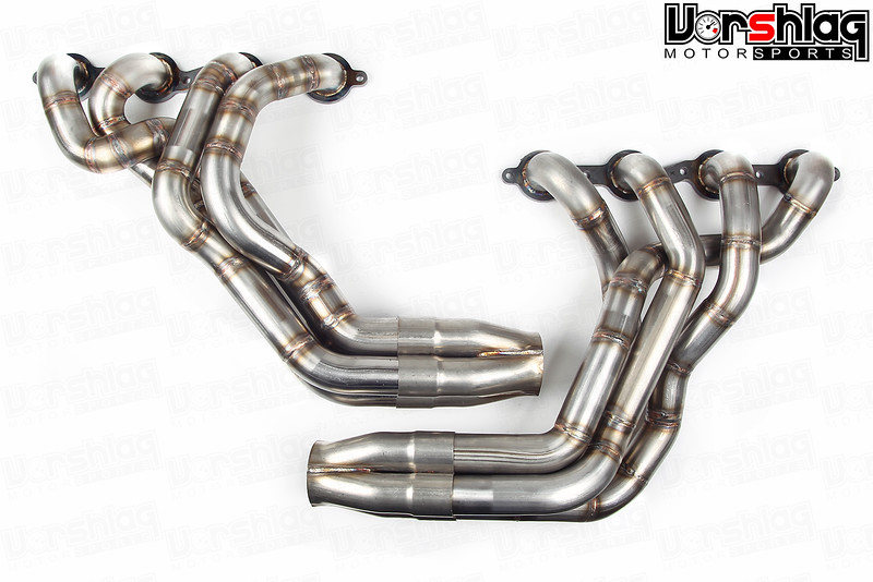
I will also cover the work involving the starter, front drive accessories, radiator, coolant lines and remote coolant reservoir in this post.
STARTER SELECTION
We always try to build our LSx swap kits so they can re-use the factory starter, which is a fairly large direct-drive unit (see below at left). They are relatively large, somewhat inexpensive, and sturdy. The truck LSx starters are different and there are many stories of these breaking the flange off one side. Truck LSx parts are almost always NOT what you want to use for a performance build.
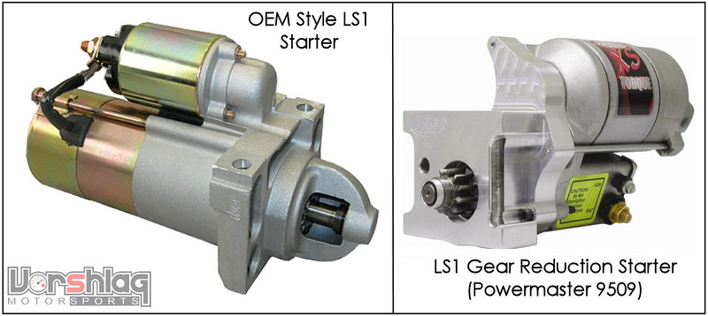
We had some serious space constraints in this engine bay when we were planning out the full length headers so Ryan spec'd out a gear reduction starter (see above right). As opposed to a direct drive starter (as most OEMs use) a gear reduction starter goes through a gear box to multiply torque (in this case 4.4:1). That gear reduction adds a lot of starting torque and is a common upgrade for higher compression engines (also common as OEM on older Chrysler V8s and many import engines). These also weigh less (8 pounds vs 11), take up less space, last longer, and do not have as much "heat soak" problem as a direct drive. They can cost more, though: the Powermaster 9509 which we used was $239, whereas the OEM style starters are $90-185 (in varying degrees of Chinese import quality).
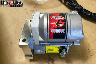
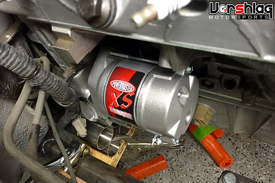
For our now "one-off" V8 swap we were no longer constrained to the stock 1998-2002 Camaro LS1 starter, and the Powermaster gear reduction unit gave us some much needed space (several inches shorter) for header routing. It will become apparent in the header section below why this was needed...
FRONT ACCESSORY DRIVE
Many of our V8 swaps utilize the 1998-02 Camaro front accessory drives, for 2 reasons. First, early on when we started doing our first LS1 swaps (2002) these engines were the most PLENTIFUL and the least costly of the aluminum LS series engines. Second, as we have found over the years, the Camaro front accessory drives were also the most COMPACT laterally.
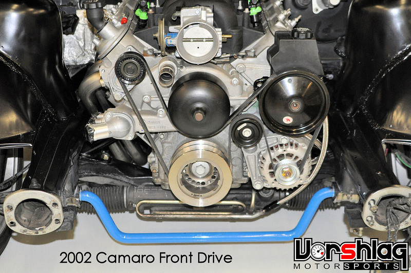
4th gen Camaro LS1 accessory drives have the NARROWEST width of any LS engine. This is in an E36 BMW with power steering.
There are about a dozen different LS front drive arrangements - many trucks, GTO/CTS-V LS1, LS2 Cadillac and G8, C5 Corvette, C6 Corvette, etc. We keep coming back to the 4th gen Camaro bits because they just fit better, width wise.
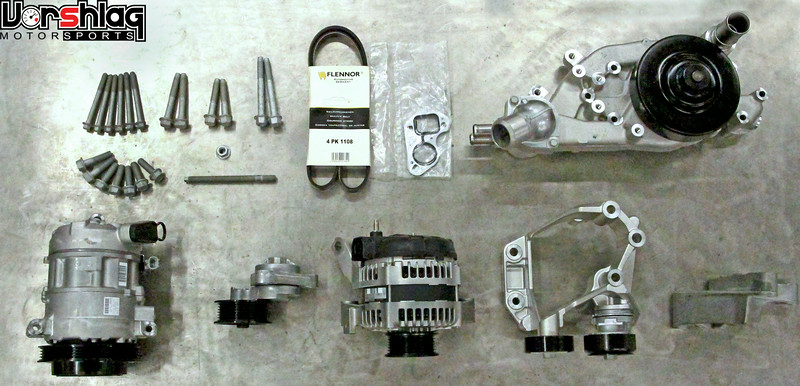
On the FR-S we had some serious front to back space constraints, and the G8 accessory drives (above and below) fit that car the best. The engine bay is short yet VERY wide in the FR-S, so any extra width in the front accessories wouldn't be an issue. Like the LS2 Corvette bits, the G8 pulleys and accessory placement were shorter front to back - by about an inch.
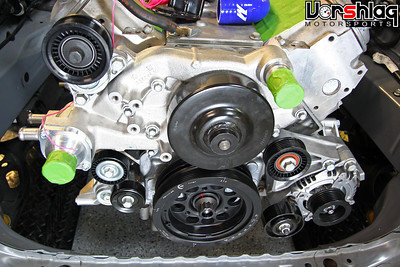
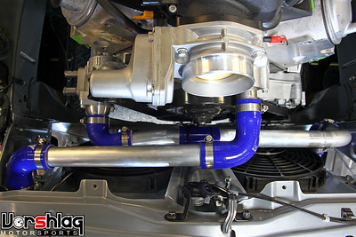
Well the engine bay in the NB Miata is totally different, and like so many of our other swaps it is narrower but doesn't have a massive front-to-back clearance problem. It came with an inline 4 that is about as long as the V8. The FR-S has a boxer 4, which is short and CRAZY wide.
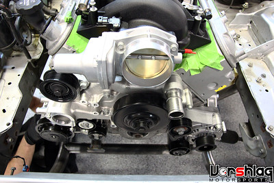
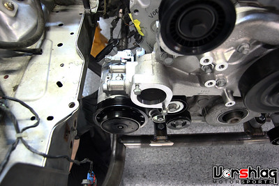
We actually mocked up the G8 accessories from the FR-S in this car (it was the mockup engine, actually). And while these accessories technically fit, the Camaro bits fit better. I'm just showing this in case any of you ever do a home brew V8 swap in an NB - these pictures above might give you some ideas of what fits.
At one point in this build I decided to switch from G8 to 4th gen Camaro accessories, but of course we already had the SFI balancer for the G8 front drive. Easily fixed - the Camaro style balancer was ordered and installed on the Miata's LS1. The 4th gen Camaro balancer has different spacing front to back, and extends farther forward to match the Camaro pulley placements.
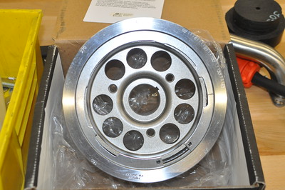
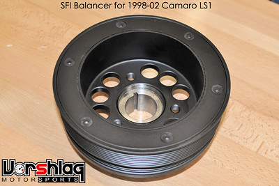
Left: G8-depth Powerbond SFI balancer. Right: Camaro depth Powerbond SFI balancer (note the deeper dish).
I like the cost-performance benefits of the Powerbond SFI balancers, and my engine builder approves. Your engine builder might have some magic witchcraft brand of SFI balancer they want to use - which is fine. Just use a quality, SFI balancer over an OEM balancer, and everyone wins.
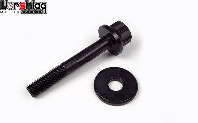
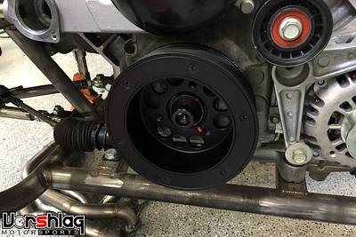
I am not a fan of the torque-to-yield OEM crank balancer bolt for the LS engines, so we always use the ARP replacement bolt when installing the balancer. Pro tip: find an old OEM LS7 balancer bolt to use for LS engine balancer installation. The LS7 bolt is considerably longer and will help "pull" the balancer onto the crank snout (its a press fit) without stripping the threads - since the longer bolt will have more thread engagement at the start. Once you have the balancer pulled onto the snout about an inch, swap in the proper length ARP crank bolt (and appropriate thread lube) and tighten to the specified ARP torque. We paint mark all critical bolts here at our shop - a good practice to quickly see if something has backed off.
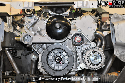
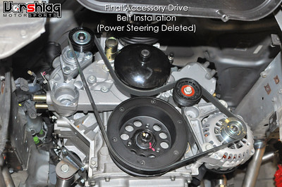
Since this car will not have power steering (we have "de-powered" the Miata rack), that means we need to bypass the power steering pump pulley in the serpentine belt routing. A quick look on the interwebs led me to the YellowBullet forums, where some trusty drag racers had sorted out this trick ages ago with the 4th gen Camaro accessories. There is an idler pulley you change, a bushing that gets machined, and the belt routing goes as shown above at right.
Of course they neglect to mention that the belt gets VERY close to a bolt head near the bottom of the alternator bracket, so we are changing that one bolt out from an OEM extended flange hex head bolt to a button head bolt, for the necessary belt clearance.
continued below

I will also cover the work involving the starter, front drive accessories, radiator, coolant lines and remote coolant reservoir in this post.
STARTER SELECTION
We always try to build our LSx swap kits so they can re-use the factory starter, which is a fairly large direct-drive unit (see below at left). They are relatively large, somewhat inexpensive, and sturdy. The truck LSx starters are different and there are many stories of these breaking the flange off one side. Truck LSx parts are almost always NOT what you want to use for a performance build.
We had some serious space constraints in this engine bay when we were planning out the full length headers so Ryan spec'd out a gear reduction starter (see above right). As opposed to a direct drive starter (as most OEMs use) a gear reduction starter goes through a gear box to multiply torque (in this case 4.4:1). That gear reduction adds a lot of starting torque and is a common upgrade for higher compression engines (also common as OEM on older Chrysler V8s and many import engines). These also weigh less (8 pounds vs 11), take up less space, last longer, and do not have as much "heat soak" problem as a direct drive. They can cost more, though: the Powermaster 9509 which we used was $239, whereas the OEM style starters are $90-185 (in varying degrees of Chinese import quality).


For our now "one-off" V8 swap we were no longer constrained to the stock 1998-2002 Camaro LS1 starter, and the Powermaster gear reduction unit gave us some much needed space (several inches shorter) for header routing. It will become apparent in the header section below why this was needed...
FRONT ACCESSORY DRIVE
Many of our V8 swaps utilize the 1998-02 Camaro front accessory drives, for 2 reasons. First, early on when we started doing our first LS1 swaps (2002) these engines were the most PLENTIFUL and the least costly of the aluminum LS series engines. Second, as we have found over the years, the Camaro front accessory drives were also the most COMPACT laterally.

4th gen Camaro LS1 accessory drives have the NARROWEST width of any LS engine. This is in an E36 BMW with power steering.
There are about a dozen different LS front drive arrangements - many trucks, GTO/CTS-V LS1, LS2 Cadillac and G8, C5 Corvette, C6 Corvette, etc. We keep coming back to the 4th gen Camaro bits because they just fit better, width wise.

On the FR-S we had some serious front to back space constraints, and the G8 accessory drives (above and below) fit that car the best. The engine bay is short yet VERY wide in the FR-S, so any extra width in the front accessories wouldn't be an issue. Like the LS2 Corvette bits, the G8 pulleys and accessory placement were shorter front to back - by about an inch.


Well the engine bay in the NB Miata is totally different, and like so many of our other swaps it is narrower but doesn't have a massive front-to-back clearance problem. It came with an inline 4 that is about as long as the V8. The FR-S has a boxer 4, which is short and CRAZY wide.


We actually mocked up the G8 accessories from the FR-S in this car (it was the mockup engine, actually). And while these accessories technically fit, the Camaro bits fit better. I'm just showing this in case any of you ever do a home brew V8 swap in an NB - these pictures above might give you some ideas of what fits.
At one point in this build I decided to switch from G8 to 4th gen Camaro accessories, but of course we already had the SFI balancer for the G8 front drive. Easily fixed - the Camaro style balancer was ordered and installed on the Miata's LS1. The 4th gen Camaro balancer has different spacing front to back, and extends farther forward to match the Camaro pulley placements.


Left: G8-depth Powerbond SFI balancer. Right: Camaro depth Powerbond SFI balancer (note the deeper dish).
I like the cost-performance benefits of the Powerbond SFI balancers, and my engine builder approves. Your engine builder might have some magic witchcraft brand of SFI balancer they want to use - which is fine. Just use a quality, SFI balancer over an OEM balancer, and everyone wins.


I am not a fan of the torque-to-yield OEM crank balancer bolt for the LS engines, so we always use the ARP replacement bolt when installing the balancer. Pro tip: find an old OEM LS7 balancer bolt to use for LS engine balancer installation. The LS7 bolt is considerably longer and will help "pull" the balancer onto the crank snout (its a press fit) without stripping the threads - since the longer bolt will have more thread engagement at the start. Once you have the balancer pulled onto the snout about an inch, swap in the proper length ARP crank bolt (and appropriate thread lube) and tighten to the specified ARP torque. We paint mark all critical bolts here at our shop - a good practice to quickly see if something has backed off.


Since this car will not have power steering (we have "de-powered" the Miata rack), that means we need to bypass the power steering pump pulley in the serpentine belt routing. A quick look on the interwebs led me to the YellowBullet forums, where some trusty drag racers had sorted out this trick ages ago with the 4th gen Camaro accessories. There is an idler pulley you change, a bushing that gets machined, and the belt routing goes as shown above at right.
Of course they neglect to mention that the belt gets VERY close to a bolt head near the bottom of the alternator bracket, so we are changing that one bolt out from an OEM extended flange hex head bolt to a button head bolt, for the necessary belt clearance.
continued below
05-12-2016, 11:26 AM
#47
continued from above
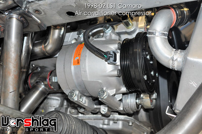
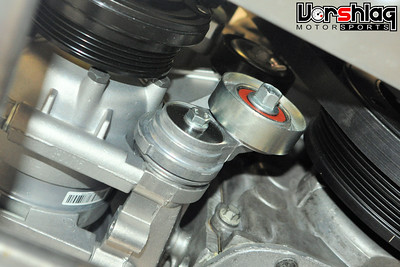
We used the A/C compressor and tensioner + idler pulley from the 1998-02 LS1 Camaro as well. This fit with a lot more room to the frame rail than the G8 bits, giving us more clearance to make the wiring and plumbing connections.
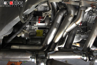

The above two pictures show the short gear reduction starer and why it was needed. This side's header was constrained and had to snake between the starter and the motor mount shown above right (which was shot later after it was final welded). You might notice that one of the header tubes changed from left to right, too.


These show even more constraints on the passenger side - the frame rail and the lower motor mount platform at the subframe. This side ended up being much harder than the driver's side on this car. Ryan designed and built the entire driver's side header and 3 of the 4 tubes on the passenger side.

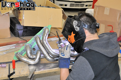
Unfortunately Ryan got buried on the tube framed 69 Camaro build so one of my other techs finished that last tube and final welded both headers. The headers were sealed off and back purged with Argon during final welding. This is a multi-step process where each tube is welded as much as can be reached while assembled, then each tube is cut away from the flange and collector. Then the inaccessible areas are welded, the tubes go BACK into the flange and collector, and they are welded at the ends. In that together-apart-together welding things can shift so you have to test fit the header into the car before it is final FINAL welded.
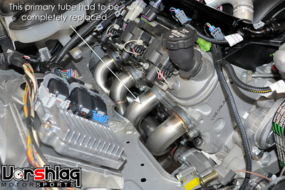
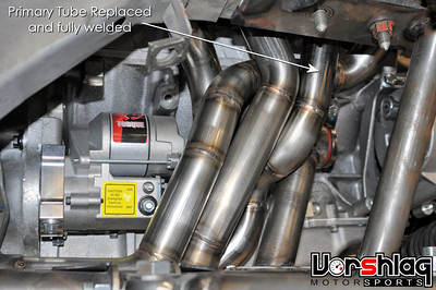
Well... things didn't go exactly to plan and months later when we were putting the car together, the one header tube Ryan didn't make was hitting a motor mount in several places. I probably shouldn't show this, but its the reality of switching between fabricators on a complex job. I don't blame the other tech, as he jumped into the middle of a project and tried to finish it. Its my fault for pulling Ryan off of a fabrication I should have let him do from start to finish.

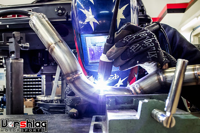
When Ryan was free he cut out the tube with clearance issue and made a new one from scratch, on my dime (not the customer's). In the end the completed long tube headers came out great and will make a nice bump in power over the little super short "block hugger" headers so many swaps use. There's good reasons why we go to all of this trouble: HORSEPOWER.

Here's a good example: The bone stock but 100% rebuilt 4th gen Camaro 5.7L LS1 V8 engine in the FR-S swap (above - and yes, I need to update that build thread) made 372 whp with headers we built, through emissions legal cats and a BRZ-spec Magnaflow rear exhaust (which that customer insisted on re-using). This engine uses a stock 1998-02 Camaro cam/head/bottom end which we changed to an LS2 intake + throttle body and our full length 1.75" dia headers. Normally a 5.7L Camaro makes 300 whp through stock manifolds / LS1 intake. So between the LS2 intake and our headers it picked up over 70 wheel... not too shabby. We'll see soon enough what this BUILT 5.7L LS1 makes in the Miata with the same headers and LS2 intake. It has forged internals, big cam, CNC ported headers... should be fun.


The headers are finally fitted, fully welded, and installed for the last time. Ground clearance looks excellent and we have started building the after-header exhaust (see pic at bottom).
COOLING SYSTEM PARTS
The cooling system for this car was always planned to have a "rolled" radiator, for clearance issues up front and potentially for use with a ducted hood down the road - if the customer so chooses. We needed to also put the radiator as low as possible to allow for an "over the top" cold air intake tube. Specifically the LS3/LS7 Corvette factory inlet tube used on many Miata swaps (hey, if it works...). Once we got the engine and radiator in place it made sense why this air tube routing was popular - but I'll show that work in another post.

When the top of the radiator is lower than the highest cooling passages inside the engine you HAVE to use a remote coolant reservoir placed higher than any point in the cooling system. Otherwise the cooling system will have an air bubble inside the engine that is impossible to bleed - which will make for all sorts of trouble. Unlike on the E36 LS swaps we've done, we skipped the custom aluminum reservoir tank for an OEM plastic unit with a built in pressure cap, shown above. It was more cost effective and we've used this exact tank in harsh conditions many times - I know it works.
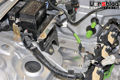
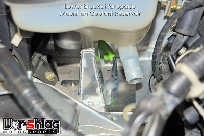
See how high in the engine bay the reservoir is placed? To make this fit inside the NB Miata engine bay at the highest point, Ryan fabricated a few brackets and mounts. The bottom of this particular tank needs a "spade" mounting socket, so Ryan built a tower (above right) with a slot in it. The left side of the tank mounts via two bolt holes, which he made on a bracket with a pair of nut-serts added (see above left). When we add the heater hoses from the water pump to the firewall, there will be a "T" in one of them that feeds into this reservoir... which will tie it into the cooling system.
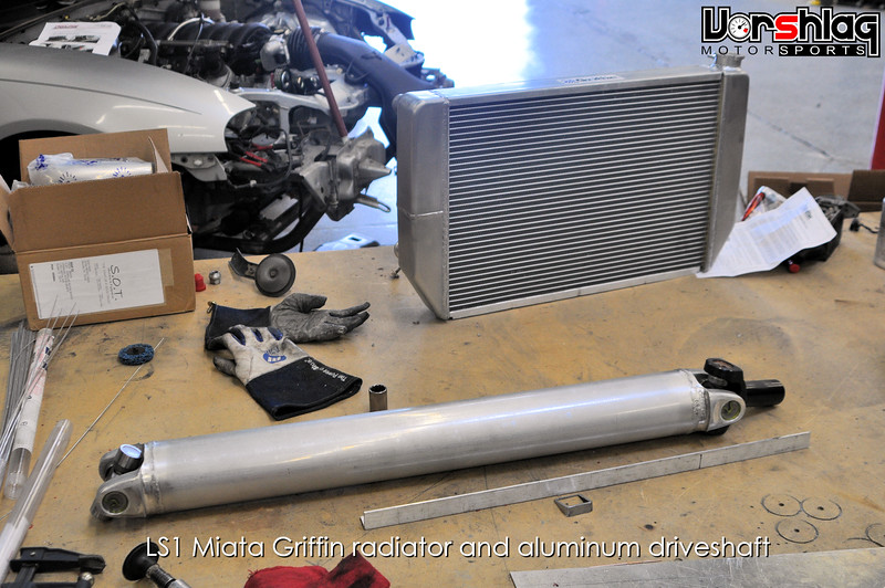
I showed this picture last time when going over the driveshaft, but now I'm showing the Griffin radiator. This company has a massive catalog of aluminum radiators shown in CAD drawings that they can make to order. Ryan spec'd out one from their drawings that had an unusual shape at the bottom and a core size that fit our unique front crossmember. It also had a dual-pass design that kept both the inlet and outlet on the right side, which is easier to package for LS engines. We placed the order and a few weeks later it arrived, complete with aluminum shroud and fan.
continued below


We used the A/C compressor and tensioner + idler pulley from the 1998-02 LS1 Camaro as well. This fit with a lot more room to the frame rail than the G8 bits, giving us more clearance to make the wiring and plumbing connections.


The above two pictures show the short gear reduction starer and why it was needed. This side's header was constrained and had to snake between the starter and the motor mount shown above right (which was shot later after it was final welded). You might notice that one of the header tubes changed from left to right, too.


These show even more constraints on the passenger side - the frame rail and the lower motor mount platform at the subframe. This side ended up being much harder than the driver's side on this car. Ryan designed and built the entire driver's side header and 3 of the 4 tubes on the passenger side.


Unfortunately Ryan got buried on the tube framed 69 Camaro build so one of my other techs finished that last tube and final welded both headers. The headers were sealed off and back purged with Argon during final welding. This is a multi-step process where each tube is welded as much as can be reached while assembled, then each tube is cut away from the flange and collector. Then the inaccessible areas are welded, the tubes go BACK into the flange and collector, and they are welded at the ends. In that together-apart-together welding things can shift so you have to test fit the header into the car before it is final FINAL welded.


Well... things didn't go exactly to plan and months later when we were putting the car together, the one header tube Ryan didn't make was hitting a motor mount in several places. I probably shouldn't show this, but its the reality of switching between fabricators on a complex job. I don't blame the other tech, as he jumped into the middle of a project and tried to finish it. Its my fault for pulling Ryan off of a fabrication I should have let him do from start to finish.


When Ryan was free he cut out the tube with clearance issue and made a new one from scratch, on my dime (not the customer's). In the end the completed long tube headers came out great and will make a nice bump in power over the little super short "block hugger" headers so many swaps use. There's good reasons why we go to all of this trouble: HORSEPOWER.

Here's a good example: The bone stock but 100% rebuilt 4th gen Camaro 5.7L LS1 V8 engine in the FR-S swap (above - and yes, I need to update that build thread) made 372 whp with headers we built, through emissions legal cats and a BRZ-spec Magnaflow rear exhaust (which that customer insisted on re-using). This engine uses a stock 1998-02 Camaro cam/head/bottom end which we changed to an LS2 intake + throttle body and our full length 1.75" dia headers. Normally a 5.7L Camaro makes 300 whp through stock manifolds / LS1 intake. So between the LS2 intake and our headers it picked up over 70 wheel... not too shabby. We'll see soon enough what this BUILT 5.7L LS1 makes in the Miata with the same headers and LS2 intake. It has forged internals, big cam, CNC ported headers... should be fun.


The headers are finally fitted, fully welded, and installed for the last time. Ground clearance looks excellent and we have started building the after-header exhaust (see pic at bottom).
COOLING SYSTEM PARTS
The cooling system for this car was always planned to have a "rolled" radiator, for clearance issues up front and potentially for use with a ducted hood down the road - if the customer so chooses. We needed to also put the radiator as low as possible to allow for an "over the top" cold air intake tube. Specifically the LS3/LS7 Corvette factory inlet tube used on many Miata swaps (hey, if it works...). Once we got the engine and radiator in place it made sense why this air tube routing was popular - but I'll show that work in another post.


When the top of the radiator is lower than the highest cooling passages inside the engine you HAVE to use a remote coolant reservoir placed higher than any point in the cooling system. Otherwise the cooling system will have an air bubble inside the engine that is impossible to bleed - which will make for all sorts of trouble. Unlike on the E36 LS swaps we've done, we skipped the custom aluminum reservoir tank for an OEM plastic unit with a built in pressure cap, shown above. It was more cost effective and we've used this exact tank in harsh conditions many times - I know it works.


See how high in the engine bay the reservoir is placed? To make this fit inside the NB Miata engine bay at the highest point, Ryan fabricated a few brackets and mounts. The bottom of this particular tank needs a "spade" mounting socket, so Ryan built a tower (above right) with a slot in it. The left side of the tank mounts via two bolt holes, which he made on a bracket with a pair of nut-serts added (see above left). When we add the heater hoses from the water pump to the firewall, there will be a "T" in one of them that feeds into this reservoir... which will tie it into the cooling system.
I showed this picture last time when going over the driveshaft, but now I'm showing the Griffin radiator. This company has a massive catalog of aluminum radiators shown in CAD drawings that they can make to order. Ryan spec'd out one from their drawings that had an unusual shape at the bottom and a core size that fit our unique front crossmember. It also had a dual-pass design that kept both the inlet and outlet on the right side, which is easier to package for LS engines. We placed the order and a few weeks later it arrived, complete with aluminum shroud and fan.
continued below
05-12-2016, 11:30 AM
#48
continued from above
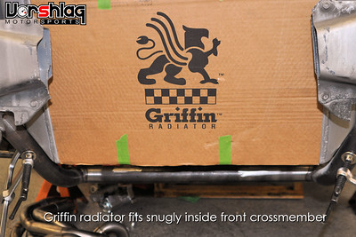

The drawing Griffin provided was spot on and the oddly shaped radiator fit perfectly into the front subframe extensions that were built.

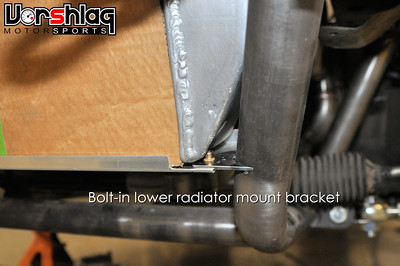
Ryan built a sheet metal lower radiator bracket with some dimple dies to give it some strength. This bolts to some some radiator mounts that attach to the subframe tubing, as shown above. There are rubber bushings between the lower bracket and the aluminum radiator - which has a very thick core for better cooling capacity and efficiency.
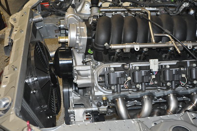
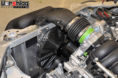
The radiator is canted forward at the top and tucks under the stock upper radiator support. Again - a quick hole added in the hood would allow for excellent venting of hot radiator air, if the owner ever wants to go that route. A splitter added to this setup would work much better with the vented hood, too.
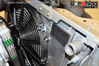

The aluminum shroud and fan help with cooling in hot Texas summers with the air conditioning cranked. The aluminum shroud bolts to the radiator, and it has enough structure to also be a good place to bolt some upper radiator brackets to. These attache with stainless button head bolts into nut-serts added to the factory upper radiator support. A straight Canton billet aluminum upper coolant "water neck" holds the thermostat and points the upper hose to the radiator neck. The OEM water neck is cast aluminum and angles differently.
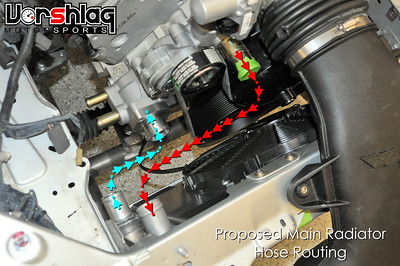
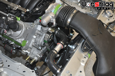
The rest of the cooling system shown in this post has to do with the radiator hoses (we'll tackle the heater hoses in another post). The picture above left shows the proposed routing for the upper and lower radiator hoses, color coded to show the hot and cold water paths. The upper hose was made from some straight aluminum sections and 90 degree silicone hose bends.


The lower radiator hose routing proved tighter than the silicone hose bends could handle, so Ryan customized the lower neck at the radiator instead.
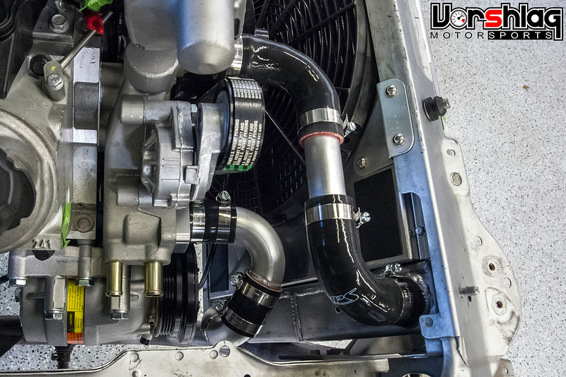
A tighter aluminum tubing bend was added to the lower outlet of the radiator, which had a better fit than the straight outlet had. Since the bottom of the radiator is closer to the engine than the top this was just the best way we could think of to make it fit and still have good coolant flow. The lower hose was then built and buttoned up the bulk of the cooling system.
WHAT'S NEXT?
There's still plenty of completed work to cover in the next post. In real time we're wrapping up wiring and fuel system plumbing, and very close to bumping the starter. We've also got a roll bar installed, drop floor pan installed, several frame bracing mods added, racing seats and harnesses, and the suspension is wrapped up.
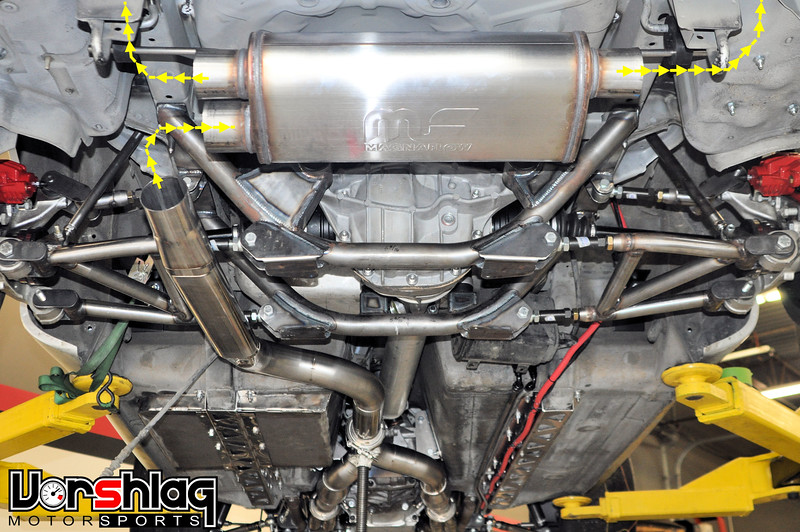
Today the custom stainless exhaust is being tack welded together and should be coming off for final welding this afternoon. We are "ones of days" away from firing up this beast.
More next time,
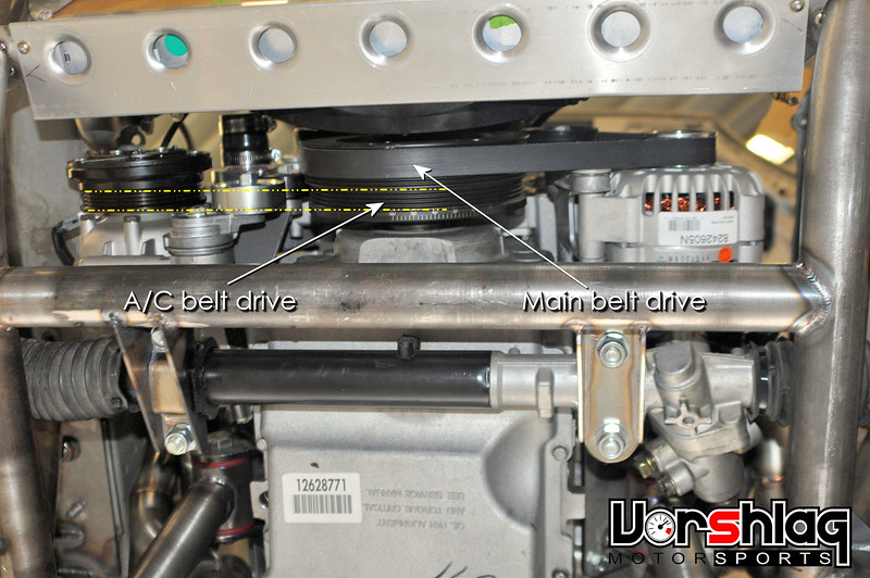
I didn't have pictures from when we originally installed the compressor, so these are from much later (and after the headers were built). All of the accessories have to be in place to design the headers around, as well as the radiator and hoses. Once all of the accessories were all in place it was time to build the headers...
CUSTOM HEADER FABRICATION
Normally when we are making an "Alpha" car that we want to make a kit from we need to make a prototype exhaust header, which we build around our production header manufacturer's CNC tubing bender dies. There's a lot of other constraints we have to build around, and it is actually a giant pain in the butt. But since we had realized "nobody is going to buy this kit for what it will cost", and moved this to a "one off" build, things sped up considerably.

We sourced some stainless U-bends and LS1 exhaust port flanges from Magnaflow, then realized we needed more and got some more stainless bends from another source. They had two different bend radii, normally not allowed with a CNC bent production header, but since it was a one-off - didn't matter. This gave Ryan a bit more flexibility to design the header better for this car, too.
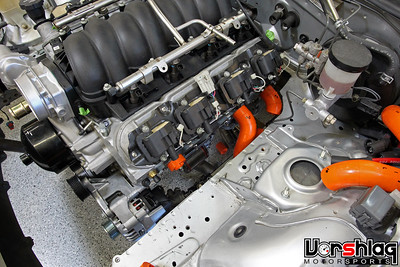
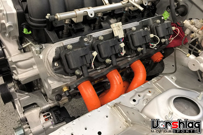
Ryan got to work on the header mock-up. The exhaust flanges were bolted to the heads and the collectors were placed down at the bottom of the engine bay where he wanted to end up. He started on the "hard side", which is almost always the driver's side, using our ICE Engine Works plastic header modeling kit - which you've seen us use in all of our past custom header builds.
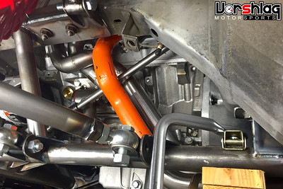
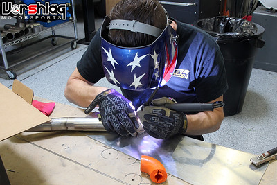
Working around the steering shaft is always tricky. At this point the steering shaft had the correct lower U-joint and a piece of 3/4" Double D shaft, but the top was just mocked up in place (we've since received the upper U-joint and built a 2-piece collapsible shaft). After the 4 tubes were completed in the snap-together plastic bends, he takes a tube out and copies it in mandrel bent stainless steel tubing... cutting, splicing, tack welding it together.
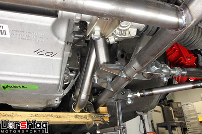
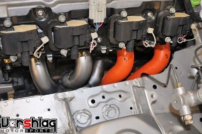
Making the tubular front crossmember opened up a LOT of room to run a proper full length header, and even though this is not destined for a kit, it IS the right way to do this V8 install. Not the most economical decision for us (since we ate tons of "kit development" time making these), but at least the header design was not too compromised trying to work around a hacked up OEM stamped steel subframe.
continued below


The drawing Griffin provided was spot on and the oddly shaped radiator fit perfectly into the front subframe extensions that were built.


Ryan built a sheet metal lower radiator bracket with some dimple dies to give it some strength. This bolts to some some radiator mounts that attach to the subframe tubing, as shown above. There are rubber bushings between the lower bracket and the aluminum radiator - which has a very thick core for better cooling capacity and efficiency.


The radiator is canted forward at the top and tucks under the stock upper radiator support. Again - a quick hole added in the hood would allow for excellent venting of hot radiator air, if the owner ever wants to go that route. A splitter added to this setup would work much better with the vented hood, too.


The aluminum shroud and fan help with cooling in hot Texas summers with the air conditioning cranked. The aluminum shroud bolts to the radiator, and it has enough structure to also be a good place to bolt some upper radiator brackets to. These attache with stainless button head bolts into nut-serts added to the factory upper radiator support. A straight Canton billet aluminum upper coolant "water neck" holds the thermostat and points the upper hose to the radiator neck. The OEM water neck is cast aluminum and angles differently.


The rest of the cooling system shown in this post has to do with the radiator hoses (we'll tackle the heater hoses in another post). The picture above left shows the proposed routing for the upper and lower radiator hoses, color coded to show the hot and cold water paths. The upper hose was made from some straight aluminum sections and 90 degree silicone hose bends.


The lower radiator hose routing proved tighter than the silicone hose bends could handle, so Ryan customized the lower neck at the radiator instead.

A tighter aluminum tubing bend was added to the lower outlet of the radiator, which had a better fit than the straight outlet had. Since the bottom of the radiator is closer to the engine than the top this was just the best way we could think of to make it fit and still have good coolant flow. The lower hose was then built and buttoned up the bulk of the cooling system.
WHAT'S NEXT?
There's still plenty of completed work to cover in the next post. In real time we're wrapping up wiring and fuel system plumbing, and very close to bumping the starter. We've also got a roll bar installed, drop floor pan installed, several frame bracing mods added, racing seats and harnesses, and the suspension is wrapped up.
Today the custom stainless exhaust is being tack welded together and should be coming off for final welding this afternoon. We are "ones of days" away from firing up this beast.
More next time,
I didn't have pictures from when we originally installed the compressor, so these are from much later (and after the headers were built). All of the accessories have to be in place to design the headers around, as well as the radiator and hoses. Once all of the accessories were all in place it was time to build the headers...
CUSTOM HEADER FABRICATION
Normally when we are making an "Alpha" car that we want to make a kit from we need to make a prototype exhaust header, which we build around our production header manufacturer's CNC tubing bender dies. There's a lot of other constraints we have to build around, and it is actually a giant pain in the butt. But since we had realized "nobody is going to buy this kit for what it will cost", and moved this to a "one off" build, things sped up considerably.

We sourced some stainless U-bends and LS1 exhaust port flanges from Magnaflow, then realized we needed more and got some more stainless bends from another source. They had two different bend radii, normally not allowed with a CNC bent production header, but since it was a one-off - didn't matter. This gave Ryan a bit more flexibility to design the header better for this car, too.


Ryan got to work on the header mock-up. The exhaust flanges were bolted to the heads and the collectors were placed down at the bottom of the engine bay where he wanted to end up. He started on the "hard side", which is almost always the driver's side, using our ICE Engine Works plastic header modeling kit - which you've seen us use in all of our past custom header builds.


Working around the steering shaft is always tricky. At this point the steering shaft had the correct lower U-joint and a piece of 3/4" Double D shaft, but the top was just mocked up in place (we've since received the upper U-joint and built a 2-piece collapsible shaft). After the 4 tubes were completed in the snap-together plastic bends, he takes a tube out and copies it in mandrel bent stainless steel tubing... cutting, splicing, tack welding it together.


Making the tubular front crossmember opened up a LOT of room to run a proper full length header, and even though this is not destined for a kit, it IS the right way to do this V8 install. Not the most economical decision for us (since we ate tons of "kit development" time making these), but at least the header design was not too compromised trying to work around a hacked up OEM stamped steel subframe.
continued below
05-12-2016, 11:39 AM
#49
continued from above
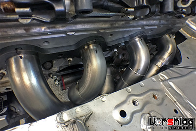
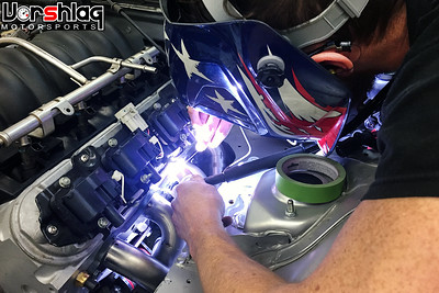
It takes a lot of hours to make a set of headers, but that's what it take to make them right.
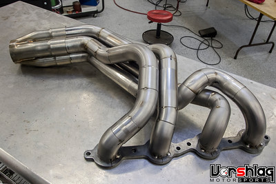
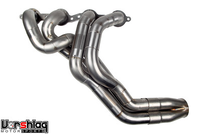
The completed driver's side header has some funky bends, but those are to clear the steering shaft - which passes through the middle of the 4 tubes. We don't needlessly add tortured bends to try to meet a perfect "equal length" design standard, as we and our engine builder have seen - this almost doesn't matter at all on a long tube, street car header design. We design around the theory of using the LEAST number of bends and the smoothest path to the collector, with a long-ish primary length in a "big enough" primary size. These are built with 1.75" dia primaries and a 3.0" dia collector.

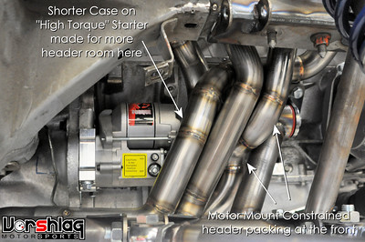
The above two pictures show the short gear reduction starer and why it was needed. This side's header was constrained and had to snake between the starter and the motor mount shown above right (which was shot later after it was final welded). You might notice that one of the header tubes changed from left to right, too.
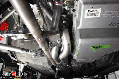
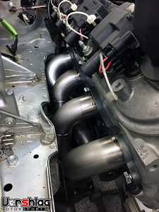
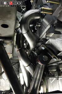
These show even more constraints on the passenger side - the frame rail and the lower motor mount platform at the subframe. This side ended up being much harder than the driver's side on this car. Ryan designed and built the entire driver's side header and 3 of the 4 tubes on the passenger side.
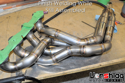

Unfortunately Ryan got buried on the tube framed 69 Camaro build so one of my other techs finished that last tube and final welded both headers. The headers were sealed off and back purged with Argon during final welding. This is a multi-step process where each tube is welded as much as can be reached while assembled, then each tube is cut away from the flange and collector. Then the inaccessible areas are welded, the tubes go BACK into the flange and collector, and they are welded at the ends. In that together-apart-together welding things can shift so you have to test fit the header into the car before it is final FINAL welded.


Well... things didn't go exactly to plan and months later when we were putting the car together, the one header tube Ryan didn't make was hitting a motor mount in several places. I probably shouldn't show this, but its the reality of switching between fabricators on a complex job. I don't blame the other tech, as he jumped into the middle of a project and tried to finish it. Its my fault for pulling Ryan off of a fabrication I should have let him do from start to finish.
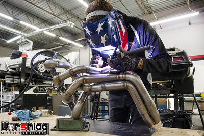

When Ryan was free he cut out the tube with clearance issue and made a new one from scratch, on my dime (not the customer's). In the end the completed long tube headers came out great and will make a nice bump in power over the little super short "block hugger" headers so many swaps use. There's good reasons why we go to all of this trouble: HORSEPOWER.
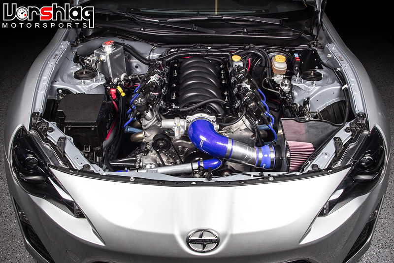
Here's a good example: The bone stock but 100% rebuilt 4th gen Camaro 5.7L LS1 V8 engine in the FR-S swap (above - and yes, I need to update that build thread) made 372 whp with headers we built, through emissions legal cats and a BRZ-spec Magnaflow rear exhaust (which that customer insisted on re-using). This engine uses a stock 1998-02 Camaro cam/head/bottom end which we changed to an LS2 intake + throttle body and our full length 1.75" dia headers. Normally a 5.7L Camaro makes 300 whp through stock manifolds / LS1 intake. So between the LS2 intake and our headers it picked up over 70 wheel... not too shabby. We'll see soon enough what this BUILT 5.7L LS1 makes in the Miata with the same headers and LS2 intake. It has forged internals, big cam, CNC ported headers... should be fun.
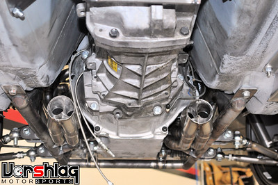
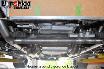
The headers are finally fitted, fully welded, and installed for the last time. Ground clearance looks excellent and we have started building the after-header exhaust (see pic at bottom).
COOLING SYSTEM PARTS
The cooling system for this car was always planned to have a "rolled" radiator, for clearance issues up front and potentially for use with a ducted hood down the road - if the customer so chooses. We needed to also put the radiator as low as possible to allow for an "over the top" cold air intake tube. Specifically the LS3/LS7 Corvette factory inlet tube used on many Miata swaps (hey, if it works...). Once we got the engine and radiator in place it made sense why this air tube routing was popular - but I'll show that work in another post.
continued below


It takes a lot of hours to make a set of headers, but that's what it take to make them right.


The completed driver's side header has some funky bends, but those are to clear the steering shaft - which passes through the middle of the 4 tubes. We don't needlessly add tortured bends to try to meet a perfect "equal length" design standard, as we and our engine builder have seen - this almost doesn't matter at all on a long tube, street car header design. We design around the theory of using the LEAST number of bends and the smoothest path to the collector, with a long-ish primary length in a "big enough" primary size. These are built with 1.75" dia primaries and a 3.0" dia collector.
The above two pictures show the short gear reduction starer and why it was needed. This side's header was constrained and had to snake between the starter and the motor mount shown above right (which was shot later after it was final welded). You might notice that one of the header tubes changed from left to right, too.
These show even more constraints on the passenger side - the frame rail and the lower motor mount platform at the subframe. This side ended up being much harder than the driver's side on this car. Ryan designed and built the entire driver's side header and 3 of the 4 tubes on the passenger side.
Unfortunately Ryan got buried on the tube framed 69 Camaro build so one of my other techs finished that last tube and final welded both headers. The headers were sealed off and back purged with Argon during final welding. This is a multi-step process where each tube is welded as much as can be reached while assembled, then each tube is cut away from the flange and collector. Then the inaccessible areas are welded, the tubes go BACK into the flange and collector, and they are welded at the ends. In that together-apart-together welding things can shift so you have to test fit the header into the car before it is final FINAL welded.
Well... things didn't go exactly to plan and months later when we were putting the car together, the one header tube Ryan didn't make was hitting a motor mount in several places. I probably shouldn't show this, but its the reality of switching between fabricators on a complex job. I don't blame the other tech, as he jumped into the middle of a project and tried to finish it. Its my fault for pulling Ryan off of a fabrication I should have let him do from start to finish.
When Ryan was free he cut out the tube with clearance issue and made a new one from scratch, on my dime (not the customer's). In the end the completed long tube headers came out great and will make a nice bump in power over the little super short "block hugger" headers so many swaps use. There's good reasons why we go to all of this trouble: HORSEPOWER.
Here's a good example: The bone stock but 100% rebuilt 4th gen Camaro 5.7L LS1 V8 engine in the FR-S swap (above - and yes, I need to update that build thread) made 372 whp with headers we built, through emissions legal cats and a BRZ-spec Magnaflow rear exhaust (which that customer insisted on re-using). This engine uses a stock 1998-02 Camaro cam/head/bottom end which we changed to an LS2 intake + throttle body and our full length 1.75" dia headers. Normally a 5.7L Camaro makes 300 whp through stock manifolds / LS1 intake. So between the LS2 intake and our headers it picked up over 70 wheel... not too shabby. We'll see soon enough what this BUILT 5.7L LS1 makes in the Miata with the same headers and LS2 intake. It has forged internals, big cam, CNC ported headers... should be fun.
The headers are finally fitted, fully welded, and installed for the last time. Ground clearance looks excellent and we have started building the after-header exhaust (see pic at bottom).
COOLING SYSTEM PARTS
The cooling system for this car was always planned to have a "rolled" radiator, for clearance issues up front and potentially for use with a ducted hood down the road - if the customer so chooses. We needed to also put the radiator as low as possible to allow for an "over the top" cold air intake tube. Specifically the LS3/LS7 Corvette factory inlet tube used on many Miata swaps (hey, if it works...). Once we got the engine and radiator in place it made sense why this air tube routing was popular - but I'll show that work in another post.
continued below
05-12-2016, 11:39 AM
#50
continued from above

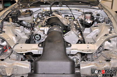
When the top of the radiator is lower than the highest cooling passages inside the engine you HAVE to use a remote coolant reservoir placed higher than any point in the cooling system. Otherwise the cooling system will have an air bubble inside the engine that is impossible to bleed - which will make for all sorts of trouble. Unlike on the E36 LS swaps we've done, we skipped the custom aluminum reservoir tank for an OEM plastic unit with a built in pressure cap, shown above. It was more cost effective and we've used this exact tank in harsh conditions many times - I know it works.


See how high in the engine bay the reservoir is placed? To make this fit inside the NB Miata engine bay at the highest point, Ryan fabricated a few brackets and mounts. The bottom of this particular tank needs a "spade" mounting socket, so Ryan built a tower (above right) with a slot in it. The left side of the tank mounts via two bolt holes, which he made on a bracket with a pair of nut-serts added (see above left). When we add the heater hoses from the water pump to the firewall, there will be a "T" in one of them that feeds into this reservoir... which will tie it into the cooling system.

I showed this picture last time when going over the driveshaft, but now I'm showing the Griffin radiator. This company has a massive catalog of aluminum radiators shown in CAD drawings that they can make to order. Ryan spec'd out one from their drawings that had an unusual shape at the bottom and a core size that fit our unique front crossmember. It also had a dual-pass design that kept both the inlet and outlet on the right side, which is easier to package for LS engines. We placed the order and a few weeks later it arrived, complete with aluminum shroud and fan.

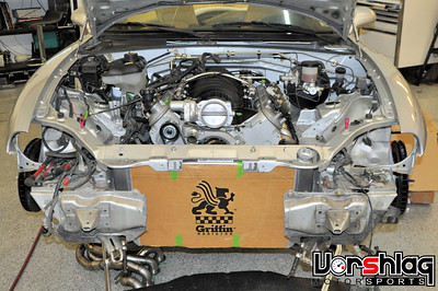
The drawing Griffin provided was spot on and the oddly shaped radiator fit perfectly into the front subframe extensions that were built.
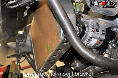

Ryan built a sheet metal lower radiator bracket with some dimple dies to give it some strength. This bolts to some some radiator mounts that attach to the subframe tubing, as shown above. There are rubber bushings between the lower bracket and the aluminum radiator - which has a very thick core for better cooling capacity and efficiency.


The radiator is canted forward at the top and tucks under the stock upper radiator support. Again - a quick hole added in the hood would allow for excellent venting of hot radiator air, if the owner ever wants to go that route. A splitter added to this setup would work much better with the vented hood, too.

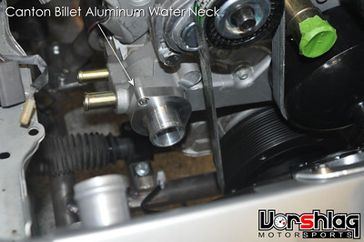
The aluminum shroud and fan help with cooling in hot Texas summers with the air conditioning cranked. The aluminum shroud bolts to the radiator, and it has enough structure to also be a good place to bolt some upper radiator brackets to. These attache with stainless button head bolts into nut-serts added to the factory upper radiator support. A straight Canton billet aluminum upper coolant "water neck" holds the thermostat and points the upper hose to the radiator neck. The OEM water neck is cast aluminum and angles differently.


The rest of the cooling system shown in this post has to do with the radiator hoses (we'll tackle the heater hoses in another post). The picture above left shows the proposed routing for the upper and lower radiator hoses, color coded to show the hot and cold water paths. The upper hose was made from some straight aluminum sections and 90 degree silicone hose bends.
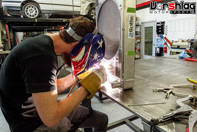
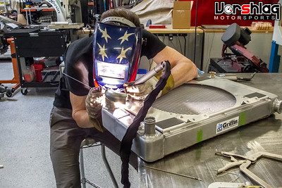
The lower radiator hose routing proved tighter than the silicone hose bends could handle, so Ryan customized the lower neck at the radiator instead.

A tighter aluminum tubing bend was added to the lower outlet of the radiator, which had a better fit than the straight outlet had. Since the bottom of the radiator is closer to the engine than the top this was just the best way we could think of to make it fit and still have good coolant flow. The lower hose was then built and buttoned up the bulk of the cooling system.
WHAT'S NEXT?
There's still plenty of completed work to cover in the next post. In real time we're wrapping up wiring and fuel system plumbing, and very close to bumping the starter. We've also got a roll bar installed, drop floor pan installed, several frame bracing mods added, racing seats and harnesses, and the suspension is wrapped up.

Today the custom stainless exhaust is being tack welded together and should be coming off for final welding this afternoon. We are "ones of days" away from firing up this beast.
More next time,
When the top of the radiator is lower than the highest cooling passages inside the engine you HAVE to use a remote coolant reservoir placed higher than any point in the cooling system. Otherwise the cooling system will have an air bubble inside the engine that is impossible to bleed - which will make for all sorts of trouble. Unlike on the E36 LS swaps we've done, we skipped the custom aluminum reservoir tank for an OEM plastic unit with a built in pressure cap, shown above. It was more cost effective and we've used this exact tank in harsh conditions many times - I know it works.
See how high in the engine bay the reservoir is placed? To make this fit inside the NB Miata engine bay at the highest point, Ryan fabricated a few brackets and mounts. The bottom of this particular tank needs a "spade" mounting socket, so Ryan built a tower (above right) with a slot in it. The left side of the tank mounts via two bolt holes, which he made on a bracket with a pair of nut-serts added (see above left). When we add the heater hoses from the water pump to the firewall, there will be a "T" in one of them that feeds into this reservoir... which will tie it into the cooling system.
I showed this picture last time when going over the driveshaft, but now I'm showing the Griffin radiator. This company has a massive catalog of aluminum radiators shown in CAD drawings that they can make to order. Ryan spec'd out one from their drawings that had an unusual shape at the bottom and a core size that fit our unique front crossmember. It also had a dual-pass design that kept both the inlet and outlet on the right side, which is easier to package for LS engines. We placed the order and a few weeks later it arrived, complete with aluminum shroud and fan.
The drawing Griffin provided was spot on and the oddly shaped radiator fit perfectly into the front subframe extensions that were built.
Ryan built a sheet metal lower radiator bracket with some dimple dies to give it some strength. This bolts to some some radiator mounts that attach to the subframe tubing, as shown above. There are rubber bushings between the lower bracket and the aluminum radiator - which has a very thick core for better cooling capacity and efficiency.
The radiator is canted forward at the top and tucks under the stock upper radiator support. Again - a quick hole added in the hood would allow for excellent venting of hot radiator air, if the owner ever wants to go that route. A splitter added to this setup would work much better with the vented hood, too.
The aluminum shroud and fan help with cooling in hot Texas summers with the air conditioning cranked. The aluminum shroud bolts to the radiator, and it has enough structure to also be a good place to bolt some upper radiator brackets to. These attache with stainless button head bolts into nut-serts added to the factory upper radiator support. A straight Canton billet aluminum upper coolant "water neck" holds the thermostat and points the upper hose to the radiator neck. The OEM water neck is cast aluminum and angles differently.
The rest of the cooling system shown in this post has to do with the radiator hoses (we'll tackle the heater hoses in another post). The picture above left shows the proposed routing for the upper and lower radiator hoses, color coded to show the hot and cold water paths. The upper hose was made from some straight aluminum sections and 90 degree silicone hose bends.
The lower radiator hose routing proved tighter than the silicone hose bends could handle, so Ryan customized the lower neck at the radiator instead.
A tighter aluminum tubing bend was added to the lower outlet of the radiator, which had a better fit than the straight outlet had. Since the bottom of the radiator is closer to the engine than the top this was just the best way we could think of to make it fit and still have good coolant flow. The lower hose was then built and buttoned up the bulk of the cooling system.
WHAT'S NEXT?
There's still plenty of completed work to cover in the next post. In real time we're wrapping up wiring and fuel system plumbing, and very close to bumping the starter. We've also got a roll bar installed, drop floor pan installed, several frame bracing mods added, racing seats and harnesses, and the suspension is wrapped up.
Today the custom stainless exhaust is being tack welded together and should be coming off for final welding this afternoon. We are "ones of days" away from firing up this beast.
More next time,


